BD-125V4-T 规格书
TLN-Y3R3-1254 3mm圆形小法兰无支架LED说明书

T-13mm Round Small Flange without stand-off LED (T-1)Features∙ Popular T-1 diameter package ∙ Choice of various viewing angles ∙ Reliable and robustDescriptions∙ The series is specially designed for applications requiring higher brightness. ∙ The LED lamps are available with different colors, intensities.Applications∙ TV set ∙ Monitor ∙ Telephone ∙ ComputerDevice Selection GuideAbsolute Maximum Ratings (Ta=25°C)Parameter SymbolValue Unit Reverse Voltage V R5 V Continuous Forward Current I F 25 mA Peak Forward Current (Duty 1/10@1KHZ)I FP160 mA Power Dissipation P d 85 mW Operating Temperature T opr -40 ~ +85 °C Storage Temperature T stg -40 ~ +100 °C Soldering Temperature (Note.1)T sol260 ± 5°CNote 1:Soldering time ≤ 5 secondsElectro-Optical Characteristics (Ta=25°C)Parameter SymbolMin. Typ. Max. Unit ConditionLuminous Intensity I V16 25 ----- mcd I F =10mAViewing Angle 2θ1/2----- 30 ----- deg I F =20mAPeak wavelength λp ----- 585 ----- nm Dominant wavelength λd----- 590----- nm Spectrum Radiation BandwidthΔλ----- 35 ----- nm Forward Voltage V F1.72.0 2.4 V Reverse CurrentI R----------10μAV R =5VNotes: Tolerance of Luminous Intensity: ±10%Tolerance of Dominant wavelength: ±1.0nmTolerance of Forward Voltage: ±0.1VRelative Intensity vs. Forward CurrentForward Current I F(mA) Forward Current vs. Ambient TemperatureAmbient Temperature T a (°C)Spectrum DistributionWavelength (nm)Forward Current vs. Forward VoltageForward Voltage (V) Typical Electro-Optical Characteristics Curves (Ta=25°C)Relative Intensity vs. Ambient TemperatureAmbient Temperature T a (°C)ForwardCurrentIF(mA)Radiation Diagram RelativeLuminousIntensity(%)ForwardCurrentIF(mA)RelativeLuminousIntensity(%)RelativeLuminousIntensity(%)Package Dimensions (In mm)Note:1. All dimensions are in millimeters, and tolerance is 0.25mm without special declared.2. An epoxy meniscus may extend about 1.5mm down the lead.Packing Quantity Specification1. 1000 Pcs/1 BagOrdering InformationTL N – Y 3 R 3 –1254 – 92–BBag or BoxFactory Location CodeFrame Structure CodeSize in mmRound LampColor TintedYellow ColorStandardTaitron LED LampHow to contact usUSA HEADQUARTERS28040 WEST HARRISON PARKWAY, VALENCIA, CA 91355-4162Tel: (800)-TAITRON (800)-824-8766 (661)-257-6060Fax: (800)-TAITFAX (800)-824-8329 (661)-257-6415Email: *****************************TAITRON COMPONENTS INCORPORATED TAIWAN BRANCH 6F., NO.190, SEC. 2, ZHONGXING RD., XINDIAN DIST., NEW TAIPEI CITY 23146, TAIWAN R.O.C.Tel: 886-2-2913-6238Fax: 886-2-2913-6239TAITRON COMPONENT TECHNOLOG SHANGHAI CORPORATION SUITE 1503, METROBANK PLAZA, 1160 WEST YAN’AN ROAD, SHANGHAI, 200052, CHINATel: +86-21-5424-9942Fax: +86-21-2302-5027。
MEMORY存储芯片MT41K128M16JT-125 IT中文规格书
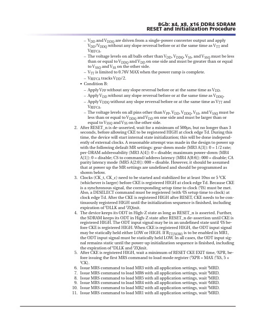
–V DD and V DDQ are driven from a single-power converter output and applyV DD /V DDQ without any slope reversal before or at the same time as V TT andV REFCA .–The voltage levels on all balls other than V DD , V DDQ , V SS , and V SSQ must be lessthan or equal to V DDQ and V DD on one side and must be greater than or equalto V SSQ and V SS on the other side.–V TT is limited to 0.76V MAX when the power ramp is complete.–V REFCA tracks V DD /2.•Condition B:–Apply V PP without any slope reversal before or at the same time as V DD .–Apply V DD without any slope reversal before or at the same time as V DDQ .–Apply V DDQ without any slope reversal before or at the same time as V TT andV REFCA .–The voltage levels on all pins other than V PP , V DD , V DDQ , V SS , and V SSQ must beless than or equal to V DDQ and V DD on one side and must be larger than orequal to V SSQ and V SS on the other side.2.After RESET_n is de-asserted, wait for a minimum of 500μs, but no longer than 3seconds, before allowing CKE to be registered HIGH at clock edge Td. During thistime, the device will start internal state initialization; this will be done independ-ently of external clocks. A reasonable attempt was made in the design to power upwith the following default MR settings: gear-down mode (MR3 A[3]): 0 = 1/2 rate;per-DRAM addressability (MR3 A[4]): 0 = disable; maximum power-down (MR4A[1]): 0 = disable; CS to command/address latency (MR4 A[8:6]): 000 = disable; CAparity latency mode (MR5 A[2:0]): 000 = disable. However, it should be assumedthat at power up the MR settings are undefined and should be programmed asshown below.3.Clocks (CK_t, CK_c) need to be started and stabilized for at least 10ns or 5 t CK(whichever is larger) before CKE is registered HIGH at clock edge Td. Because CKEis a synchronous signal, the corresponding setup time to clock (t IS) must be met.Also, a DESELECT command must be registered (with t IS setup time to clock) atclock edge Td. After the CKE is registered HIGH after RESET, CKE needs to be con-tinuously registered HIGH until the initialization sequence is finished, includingexpiration of t DLLK and t ZQinit.4.The device keeps its ODT in High-Z state as long as RESET_n is asserted. Further,the SDRAM keeps its ODT in High-Z state after RESET_n de-assertion until CKE isregistered HIGH. The ODT input signal may be in an undefined state until t IS be-fore CKE is registered HIGH. When CKE is registered HIGH, the ODT input signalmay be statically held either LOW or HIGH. If R TT(NOM) is to be enabled in MR1,the ODT input signal must be statically held LOW. In all cases, the ODT input sig-nal remains static until the power-up initialization sequence is finished, includingthe expiration of t DLLK and t ZQinit.5.After CKE is registered HIGH, wait a minimum of RESET CKE EXIT time, t XPR, be-fore issuing the first MRS command to load mode register (t XPR = MAX (t XS, 5 ×t CK).6.Issue MRS command to load MR3 with all application settings, wait t MRD.7.Issue MRS command to load MR6 with all application settings, wait t MRD.8.Issue MRS command to load MR5 with all application settings, wait t MRD.9.Issue MRS command to load MR4 with all application settings, wait t MRD.10.Issue MRS command to load MR2 with all application settings, wait t MRD.11.Issue MRS command to load MR1 with all application settings, wait t MRD.8Gb: x4, x8, x16 DDR4 SDRAM RESET and Initialization ProcedureFigure 38: MPR READ-to-WRITE TimingT0T1T2DQ DQS_t,DQS_cTa0Ta1Ta2Ta3Ta4Ta5Ta6Tb0Tb1Tb2Command Address CKECK_tCK_cDon’t CareNotes: 1.Address setting:A[1:0] = 00b (data burst order is fixed starting at nibble, always 00b here)A2 = 0b (for BL = 8, burst order is fixed at 0, 1, 2, 3, 4, 5, 6, 7)BA1 and BA0 indicate the MPR locationA10 and other address pins are "Don’t Care," including BG1 and BG0. A12 is "Don’tCare" when MR0 A[1:0] = 00 and must be 1b when MR0 A[1:0] = 012.Address setting:BA1 and BA0 indicate the MPR locationA[7:0] = data for MPRBA1 and BA0 indicate the MPR locationA10 and other address pins are "Don’t Care"3.Parity latency (PL) is added to data output delay when CA parity latency mode is ena-bled.MPR WritesMPR access mode allows 8-bit writes to the MPR Page 0 using the address bus A[7:0].Data bus inversion (DBI) is not allowed during MPR WRITE operation. The DRAM willmaintain the new written values unless re-initialized or there is power loss.The following steps are required to use the MPR to write to mode register MPR Page 0.1.The DLL must be locked if enabled.2.Precharge all; wait until t RP is satisfied.3.MRS command to MR3[2] = 1 (enable MPR data flow) and MR3[1:0] = 00 (MPRPage 0); writes to 01, 10, and 11 are not allowed.4.t MRD and t MOD must be satisfied.5.Redirect all subsequent WRITE commands to specific MPR x location.6.Issue WR or WRA command:a.BA1 and BA0 indicate MPR x location1.00 = MPR02.01 = MPR13.10 = MPR24.11 = MPR3b.A[7:0] = data for MPR Page 0, mapped A[7:0] to UI[7:0].8Gb: x4, x8, x16 DDR4 SDRAM Multipurpose Register。
如何确认CDF

如何确认CDFCDF——也就是我们常说的元器件清单,是德文的缩写,它是产品组成部件的有关电气安全方面的详细资料。
经过相关测试认证以后的组成部件,其参数能保证产品部件材料的一致性和延续性,并且对生产起指导作用。
鉴于CDF的作用如此巨大,所以一份准确、完整的CDF是非常重要的。
那么,怎样才能迅速完成一份高质量的CDF呢?以下我们就来讲讲TUVPS确认CDF的程序和方法,仅供大家参考。
TUVPS确认CDF的程序的基本程序如下:1.在生产企业准备做产品相关认证时,生产企业和TUVPS商务合同确立以后,TUVPS的项目工程师就会要求企业提供相关产品的认证申请(申请单和委托单)、产品说明书、原理图、系统图和元件材料表等相关资料和产品样机,并且工厂对重要的电气部件提供CDF。
2.TUVPS项目工程师审阅相关资料并预检样品,根据企业提供的元器件清单、供应商所提供的元器件认证证书、相关网站和样品检查的结果来核对CDF 的内容。
3.TUVPS项目工程师核对好CDF以后,就会把CDF发送回生产企业的相关人员进行再确认并签名、盖章,确认完毕后E-mail回TUVPS项目工程师处,TUVPS 最后再核对无误后,打印两份原件并签名盖章后,寄一份给企业,一份由TUVPS 保留,这就是最终的CDF,这两份的内容是相同的。
在了解了TUVPS确认CDF的基本程序以后,我们就详细讲一下TUVPS确认CDF内容的方法:(出示一张CDF)首先是CDF的首页。
1.申请人,生产商,按照正确的名字填写。
2.产品名称、型号、规格等按照产品说明书填写。
3.结构特征、IP防护等级、与电源的连接、工作方式等按照产品的要求和实际状况来填写。
4.外壳要填写主要部件的名称和材料内容。
第二页及其以后就是表格的内容。
TUVPS的CDF的表格共有四列:第一列是元器件名称,注意要填写规范的名称,即此元件证书上的名称,不能随便给元器件起名,否则容易造成别人的误解;第二列是元器件生产商名称,元器件生产商名称要按照其取得的证书上的名称填写准确;第三列是元器件的型号、规格等内容,并且必须与证书上的内容一致;第四列是元器件通过的相关认证标志,要把元器件通过的相关认证标志和认证号码填写清楚。
MARUWA MWSL1252 GPS L1 天线规格书说明书

1.ScopeThis specification applies to the MARUWA MWSL1252 GPS L1 antenna which is intentionally designed to resonate in free-space at 1593.5MHz so that it can be tuned by the embedding configuration to the GPS L1 frequency: 1575.42MHz.The MWSL1252 part is designed for applications where packaging will cause a moderate level of down-tuning. Forapplications with a higher degree of detuning the MWSL1251 part should be selected.2.SpecificationsMinimum Typical Maximum UnitPart Number MWSL1251 (MARUWA dwg N o: MEFP125X0022A140101)Type Dielectric-loaded Quadrifilar HelixConnector Type Refer to embedding information / connection diagramsFree Space Frequency 1593.5MHzEmbedded Frequency 1575.42MHzPolarisation Right-hand Circular PolarisedIntegrated Gain (evaluation PCB)-3.0dBic at zenithBeamwidth >115DegreesBandwidth (3dB)15MHzAxial Ratio <1.5at zenithVSWR <2.0:1 2.3:1Impedance 50ΩOperating Temperature -402085°C Overall Dimensions Refer to mechanical drawings mmWeight 7.0grams3.DimensionsBasic MWSL1252 form:Rev.Date Description Approved Checked PreparedK.Inagaki F.Frimpong Product Specification (Preliminary)MARUWA Antenna ProductsDocument №MEPS-12520042150101MWSL12520103 Feb. 15Issue of the first edition O.Leisten Notes:1.MARUWA Europe assembly drawingMEFP125X022******* applies.2. Units in mm.3. For connection layout and pad-size, through-hole andconnector details please refer to pad layout and designationdefinitions.MWSL1252S form with loosely fitting translucent sleeve.Notes:1.MARUWA Europe assembly drawingMEFP125XS28A140101 applies.2. Units in mm.3. Transluscent sleeve unit: METC12XX028A140101 shownfitted but actually shipped separately.4. For connection layout and pad-size, through-hole andconnector details please refer to pad layout and designationMWSL1252R form with loosely fitting black radome cap.Notes:1.MARUWA Europe assembly drawingMEFP1252R04B140101 applies.2. Units in mm.3. Black cap/radome unit: METC120X158140101 shownfitted but actually shipped separately.4. For connection layout and pad-size, through-hole andconnector details please refer to pad layout and designation0103 Feb. 15Issue of the first edition K.Inagaki F.Frimpong O.Leisten Rev.Date Description Approved Checked Prepared4.Product DescriptionTypical Gain PatternThe MWSL1252 GPS L1 miniature dielectric-loaded antenna uses MARUWA’s distinctive materials technology to provide high circularly-polarised gain in a small size for particularly tightly integrated applications.It enables excellent GPS performance in such tightly integrated devices that require good positional eful gain uplift, due to near-field reflections, can be achieved throughinstallation according to MARUWA design guidelines.The MWSL1252 antenna has a sharp filtering response and is particularly suitable for applications where:*The device is hand-held, body-worn, or otherwise surrounded by materials of high relative dielectric-constant which would de-tune other antennas.* The antenna is installed in close proximity to other antennas sharing the same device housing and ground-plane: for example Bluetooth®, WiFi, LTE,WiMax and other cellular radio antennas.* The antenna must fit into a very small installation volume with close proximity to other components and little or no space available for a ground-plane.* The orientation of the device is random.* The antenna must be embedded into the device.The MWSL1252 antenna is balanced, which isolates it from the device ground enabling it to reject common-mode noise present on the device ground-plane. The construction and materials of the antenna constrain its near-field region to occupy a very small volume so that materials near theantenna cause negligible de-tuning effects. Therefore the antenna maintains its pattern and efficiency in the presence of dielectric loading. As a dielectric-loaded antenna the MWSL1252 has a stablefiltering effect; attenuating signals from common cellular and ISM frequency bands by as much as 30dB without external filtering.0849096180-96-90-84Elevation Gain (G θ) For Azimuth (φ)0264270276Azimuth Gain (G φ) for Elevation (θ)Rev.Date Description Approved Checked PreparedMARUWA Antenna ProductsDocument №MEPS-12520042150101MWSL12520103 Feb. 15Issue of the first edition K.Inagaki F.Frimpong O.Leisten A second mode of installation is one in which the MWSL1252 isembedded into the housing with features surrounding theantenna causing a moderate degree of down-tuning. Though it iselectrically isolated from the device ground plane, through theaction of an integrated balun, the MWSL1252 antenna can beexpected to increase efficiency by up to 100% when integratedinto a ground plane due to constructive near-field signalreflections. This product is generally used in a class of smallportable devices that have slim styling so that there is no spacefor a ground-plane that is laterally disposed with respect to theantenna-axis. It is therefore specified as embedded into aground-plane that is co-planar with the antenna axis.The MWSL1252 is designed for applications with embedding configurations that tune theantenna from the free-space resonant frequency of 1593.5MHz to the GPS L1 frequency of1575.42MHz. Such configurations include the co-planar ground-plane as shown above with10mm offset between the circuit-board copper-ground plane and the side of the antennatogether with further de-tuning caused by the plastic housing of the product.For applications with more tight embedding MARUWA offers the MWSL1251 part which is tuned to a free-space frequency of 1603.5MHz.The MARUWA MWSL1252 antenna is designed for two modes ofinstallation.The first (and preferred) configuration is as a stand-aloneextenally mounted antenna (outside of the housing) with the black-capradome fitted (MARUWA part number: METC120X0158140101). Theantenna can be incorporated into a stand-alone package with a co-axialconnector output as might be configured in a screw-on packageformat. In such a configuration the MWSL1252 part may be embeddedwithin a plastic over-moulding. Alternatively the antenna can beconnected to an internal circuit board using the connection pads butwith the product housing closing into the groove of the black capradome. As an another alternative the customer may choose to designa radome of a different style. Such a design must be implemented witha suitable low-loss material which has the same dielectric loadingeffect as the MARUWA METC120X0158141010 black cap/radome.Typical Impedance Response Typical Return Loss Response Filtering Response Rev.Date Description Approved Checked PreparedMARUWA Antenna ProductsDocument №MEPS-12520042150101MWSL1252O.Leisten Cellular 900GPS L1Cellular 18003G Rx ISM 2.4190021102170-29-32-30-40-38-46-40-3K.Inagaki F.Frimpong 0103 Feb. 2015Issue of the first edition Frequency (MHz)S 21 (dB)24002480860970157517001800-26-36A set of match loci for a typical MWSL1252antenna is shown as plotted on a Smith chartwhich is normalised to 50 . The dielectric-loaded structure of the antenna causes thematch characteristic not to change significantlywhen is close proximity to the human body. Forexample the |S 11| response is remarkablyunchanged as a human hand is brought as closeas 5mm from the antenna.This MARUWA dielectric-loaded antenna technology delivers a major advantage with regard toimmunity to de-tuning when brought into close proximity to human tissues and other "in-use"causes of dielectric loading. The MWSL1252 antenna retains efficiency and polarisation near the human body. Conventional antennas may lose 5-10dB of gain or efficiency in similarcircumstances of use.The frequency stability of the MWSL1252antenna is further illustrated in the graph ofreturn-loss magnitude (in dB)for fourdifferent levels of dielectric loading (mmoffset from a phantom hand). Once again itdemonstrates that minimal detuning occursuntil the antenna is within 10 mm of thephantom hand.Page 6/6Embedding Information Pad Layout and designation Pad Number Function 1Ground 2Signal 3GroundDimensionsmm ± 0.1A3.2B1.45C1.7D0.5E1.5F3.5G 3.5Ordering Guide for the MWSL1252 AntennaMaruwa PartDescription MOQ Pack Size MWSL1252 with PBC-feed connection.MWSL1252SMWSL1252 with sleeve (for embedded use).Please note that when MWSL1252S or MWSL1252R parts are ordered the sleeve/radome parts shall be delivered in separate packaging and will not be fitted to the MWSL1252 product. The radome and sleeve parts are designed to fit loosely.5.Notes1. The contents of this document assure the characteristics and quality of the antenna components themselves.2. Please ensure that they work correctly in the installed configuration and method of use of your equipment.Rev.Date Description Approved Checked PreparedProduct Specification (Preliminary)MARUWA Antenna ProductsO.Leisten Document №MEPS-12520042150101MWSL125201K.Inagaki MWSL1252R MWSL1252 with radome (for external use).400400400400400400MWSL1252Issue of the first edition 03 Feb. 2015 F.Frimpong A typical installation into a plastic housing isshown. It embodies the combination of ahand-soldered electrical connection to thehost PCB with mechanical support, in theform of plastic cradle-ribs, to implement ashock-resistant structure. Of course it isimportant to ensure that the assembly is notunder strain when the parts are fittedtogether. If accurate assembly jigs areavailable, the antenna can be soldered to theboard and thereafter the board-assemblycan be fitted into the housing. Alternativelythe MWSL1252 can be soldered to the boardwhich is itself fitted into the housing. Theinstallation is completed when the lid half ofthe housing, with the opposing antenna ribs,is fitted. Further installation information canbe obtained from MARUWA's integrationguideline documents.The "ground exclusion area" applies to all PCB layers. Ground-plane within this regiondegrades the 50Ωmatch.123F D EG AA B B C Ground。
MEMORY存储芯片MT41J512M8THV-125 H中文规格书
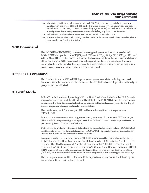
18.Idle state is defined as all banks are closed (t RP , t DAL, and so on, satisfied), no databursts are in progress, CKE is HIGH, and all timings from previous operations are satis-fied (t MRD, t MOD, t RFC, t ZQinit, t ZQoper, t ZQCS, and so on), as well as all self refresh ex-it and power-down exit parameters are satisfied (t XS, t XP , t XSDLL, and so on).19.Self refresh mode can be entered only from the all banks idle state.20.For more details about all signals, see the Truth Table – Command table; must be a legalcommand as defined in the table.NOP CommandThe NO OPERATION (NOP) command was originally used to instruct the selectedDDR4 SDRAM to perform a NOP (CS_n = LOW and ACT_n, RAS_n/A16, CAS_n/A15, and WE_n/A14 = HIGH). This prevented unwanted commands from being registered during idle or wait states. NOP command general support has been removed and the com-mand should not be used unless specifically allowed, which is when exiting maximum power-saving mode or when entering gear-down mode.DESELECT CommandThe deselect function (CS_n HIGH) prevents new commands from being executed;therefore, with this command, the device is effectively deselected. Operations already in progress are not affected.DLL-Off ModeDLL-off mode is entered by setting MR1 bit A0 to 0, which will disable the DLL for sub-sequent operations until the A0 bit is set back to 1. The MR1 A0 bit for DLL control can be switched either during initialization or during self refresh mode. Refer to the Input Clock Frequency Change section for more details.The maximum clock frequency for DLL-off mode is specified by the parameter t CKDLL_OFF .Due to latency counter and timing restrictions, only one CL value and CWL value (in MR0 and MR2 respectively) are supported. The DLL-off mode is only required to sup-port setting both CL = 10 and CWL = 9.DLL-off mode will affect the read data clock-to-data strobe relationship (t DQSCK), but not the data strobe-to-data relationship (t DQSQ, t QH). Special attention is needed to line up read data to the controller time domain.Compared with DLL-on mode, where t DQSCK starts from the rising clock edge (AL +CL)cycles after the READ command, the DLL-off mode t DQSCK starts (AL + CL - 1) cy-cles after the READ command. Another difference is that t DQSCK may not be small compared to t CK (it might even be larger than t CK), and the difference between t DQSCK (MIN) and t DQSCK (MAX) is significantly larger than in DLL-on mode. The t DQSCK (DLL-off) values are undefined and the user is responsible for training to the data-eye.The timing relations on DLL-off mode READ operation are shown in the following dia-gram, where CL = 10, AL = 0, and BL = 8.8Gb: x4, x8, x16 DDR4 SDRAM NOP CommandTable 4: State Diagram Command DefinitionsNote: 1.See the Command Truth Table for more details.8Gb: x4, x8, x16 DDR4 SDRAM State Diagram。
NCB-H1812D125TR中文资料

4.0±0.1
G ±0.05
+0.1 ∅1.5-0
0.30 ±0.05
E±0.05
E±0.05
W±0.2
W±0.2
B±0.1
B±0.1
TAPE DIMENSIONS (mm)
A B T W E F G Chips/Reel Fig. 1.14 1.75 1.15 8.0 3.5 1.75 2.0 4000 1 1.54 2.32 1.15 8.0 3.5 1.75 2.0 4000 1
NCB Series
D (mm)
1.1 ± 0.2 1 3.2 ± 0.2 1.6 ± 0.2 0.5 ± 0.3
1206
1.6 ± 0.2
1210
1
3.2 ± 0.2
2.5 ± 0.2
1.3 ± 0.2
0.5 ± 0.3
1806
1
4.5 ± 0.25
1.6 ± 0.2
1.6 ± 0.2
0.5 ± 0.3
DIMENSIONS (mm)
Size 0603 0805 1206 1210 1806 1812 1612 3312 3119 A 1.0 1.0 1.00 1.00 1.05 1.05 1.70 1.70 1.70 B 0.6 1.2 1.80 2.70 1.80 3.50 2.00 2.00 2.00 C 0.8 1.2 2.00 2.00 3.30 3.30 2.20 6.60 5.80
®
NIC COMPONENTS
251
元器件交易网
Ferrite Chip Beads
MEMORY存储芯片MT41K128M16JT-125A中文规格书
MM PUDD =× 100R ONPU,max - R ONPU,minR ON,nomMM PDDD =× 100R ONPD,max - R ONPD,minR ON,nom 7.The lower and upper bytes of a x16 are each treated on a per byte basis.8.The minimum values are derated by 9% when the device operates between –40°C and0°C (T C ).Output Driver Temperature and Voltage SensitivityIf temperature and/or voltage change after calibration, the tolerance limits widen ac-cording to the equations and tables below.˂T = T - T(@calibration); ˂V = V DDQ - V DDQ (@ calibration); V DD = V DDQTable 125: Output Driver Sensitivity DefinitionsTable 126: Output Driver Voltage and Temperature SensitivityAlert DriverA functional representation of the alert output buffer is shown in the figure below. Out-put driver impedance, R ON , is defined as follows.8Gb: x4, x8, x16 DDR4 SDRAM Electrical Characteristics – AC and DC Output Driver Charac-teristics4.BL8 setting activated by either MR0[1:0] = 00 or MR0[1:0] = 01 and A12 = 1 during WRITE command at T0 and READ command at T15.5.CA parity = Disable, CS to CA latency = Disable, Read DBI = Disable, Write DBI = Disable,Write CRC = Disable.6.The write timing parameter (t WTR_S) is referenced from the first rising clock edge after the last write data shown at T13.Figure 185: WRITE (BL8) to READ (BL8) with 1t CK Preamble in Same Bank GroupCommand DQ CK_t CK_c DQS_t,DQS_cBank GroupAddress Address Notes: 1.BL = 8, WL = 9 (CWL = 9, AL = 0), CL = 11, READ preamble = 1t CK, WRITE preamble =1t CK.2.DI b = data-in from column b .3.DES commands are shown for ease of illustration; other commands may be valid at these times.4.BL8 setting activated by either MR0[1:0] = 00 or MR0[1:0] = 01 and A12 = 1 during WRITE command at T0 and READ command at T17.5.CA parity = Disable, CS to CA latency = Disable, Read DBI = Disable, Write DBI = Disable,Write CRC = Disable.6.The write timing parameter (t WTR_L) is referenced from the first rising clock edge after the last write data shown at T13.8Gb: x4, x8, x16 DDR4 SDRAM WRITE Operation。
研磨机说明书
MB4363B(PC)半自动双盘研磨机使用说明书目录1、机床外观图----------------------------------------------------12、主要用途和特性----------------------------------------------23、主要规格和参数--------------------------------------------2-34、传动系统-----------------------------------------------------4-75、主要结构与性能-------------------------------------------8-156、液压系统---------------------------------------------------16-257、电气系统---------------------------------------------------26-348、冷却系统-------------------------------------------------------359、润滑系统-------------------------------------------------------3610、吊运与安装------------------------------------------------37-3911、调整与操作--------------------------------------------40-5112、附件----------------------------------------------------52-55注:由于机床经常不断地改进,如机床的结构性能无重大改变时,本说明书不随时修改。
二.主要用途和特性本机床为万能机床,用于研磨零件的平面和圆柱面。
5.250BTC 全系列-最新规格书-欧力-2019
规格承认书 Specification for approval
产品名称:5.250/BTC系列 慢断型 陶瓷管保险丝 Product Type: 5.250/BTC Series Time-Lag Ceramic Tube Fuse
Version No.:2013001
Reomax Electronics (HK) Limited Add: 5th Floor, Bright way tower, No.33 Mong kok road, Kowloon Hong Kong Web: http://www.reomaxfuse.net
Spec. No.: SFA-5.250BTC Reomax Electronics Co., LTD © 2013 Reomax Electronics Specifications are subject to change without notice Revised: 01/25/13
5.250/BTC系列产品规格书 5.250/BTC Series Specification
2 目录Contents
1. 适用范围 / Scope of Application ......................................................................................................................... 3 2. 安规认证标准及编号 / Standards and Agency Approvals ................................................................................. 3 3. 产品标示 / Product Marking ............................................................................................................................... 4 4. 外观及形状 / Appearances and Configuration ................................................................................................... 5 5. 结构及尺寸 / Dimensions and Structure ............................................................................................................ 5 6. 材料明细 / Material Details ................................................................................................................................ 6 7. 产品特性 / Product Characteristics .................................................................................................................... 6 8. 电气特性 / Electrical Characteristics .................................................................................................................. 6 9. 环境特性 / Environmental Characteristic ........................................................................................................... 8 10. 安装建议 / Installation Recommendations ........................................................................................................ 9 11. 包装 / Packaging ................................................................................................................................................ 10 12. 其他 / Others ..................................................................................................................................................... 11 附件I: 安规证书 / Appendix I: Safety approval certificates ................................................................................... 11 © 2013 Reomax Electronics Specifications are subject to change without notice Revised: 01/25/13
MEMORY存储芯片MT41J128M16HA-125IT中文规格书
15.4.6.5Trip-Zone Clear Register(TZCLR)The trip-zone clear register(TZCLR)is shown in Figure15-85and described in Table15-76.Figure15-85.Trip-Zone Clear Register(TZCLR)153210Reserved OST CBC INTR-0R/W-0R/W-0R/W-0 LEGEND:R/W=Read/Write;R=Read only;-n=value after resetTable15-76.Trip-Zone Clear Register(TZCLR)Field Descriptions Bits Name Value Description15-3Reserved0Reserved2OST Clear Flag for One-Shot Trip(OST)Latch0Has no effect.Always reads back a0.1Clears this Trip(set)condition.1CBC Clear Flag for Cycle-By-Cycle(CBC)Trip Latch0Has no effect.Always reads back a0.1Clears this Trip(set)condition.0INT Global Interrupt Clear Flag0Has no effect.Always reads back a0.1Clears the trip-interrupt flag for this ePWM module(TZFLG[INT]).NOTE:No further EPWMxTZINT interrupts will be generated until the flag is cleared.If the TZFLG[INT]bit is cleared and any of the other flag bits are set,then another interrupt pulse will be generated.Clearing all flag bits will prevent further interrupts.15.4.6.6Trip-Zone Force Register(TZFRC)The trip-zone force register(TZFRC)is shown in Figure15-86and described in Table15-77.Figure15-86.Trip-Zone Force Register(TZFRC)153210Reserved OST CBC RsvdR-0R/W-0R/W-0R-0 LEGEND:R/W=Read/Write;R=Read only;-n=value after resetTable15-77.Trip-Zone Force Register(TZFRC)Field Descriptions Bits Name Value Description15-3Reserved0Reserved2OST Force a One-Shot Trip Event via Software0Writing of0is ignored.Always reads back a0.1Forces a one-shot trip event and sets the TZFLG[OST]bit.1CBC Force a Cycle-by-Cycle Trip Event via Software0Writing of0is ignored.Always reads back a0.1Forces a cycle-by-cycle trip event and sets the TZFLG[CBC]bit.0Reserved0Reserved15.4.3.3Action-Qualifier Software Force Register(AQSFRC)The action-qualifier software force register(AQSFRC)is shown in Figure15-75and described inTable15-64.Figure15-75.Action-Qualifier Software Force Register(AQSFRC) 158******** Reserved RLDCSF OTSFB ACTSFB OTSFA ACTSFA R-0R/W-0R/W-0R/W-0R/W-0R/W-0 LEGEND:R/W=Read/Write;R=Read only;-n=value after resetTable15-64.Action-Qualifier Software Force Register(AQSFRC)Field Descriptions Bit Field Value Description15-8Reserved0Reserved7-6RLDCSF0-3h AQCSFRC Active Register Reload From Shadow Options0Load on event counter equals zero1h Load on event counter equals period2h Load on event counter equals zero or counter equals period3h Load immediately(the active register is directly accessed by the CPU and is not loaded from theshadow register).5OTSFB One-Time Software Forced Event on Output B0Writing a0(zero)has no effect.Always reads back a0This bit is auto cleared once a write to this register is complete,that is,a forced event is initiated.)This is a one-shot forced event.It can be overridden by another subsequent event on output B.1Initiates a single s/w forced event4-3ACTSFB0-3h Action when One-Time Software Force B Is invoked0Does nothing(action disabled)1h Clear(low)2h Set(high)3h Toggle(Low->High,High->Low)Note:This action is not qualified by counter direction(CNT_dir)2OTSFA One-Time Software Forced Event on Output A0Writing a0(zero)has no effect.Always reads back a0.This bit is auto cleared once a write to this register is complete(that is,a forced event is initiated).1Initiates a single software forced event1-0ACTSFA0-3h Action When One-Time Software Force A Is Invoked0Does nothing(action disabled)1h Clear(low)2h Set(high)3h Toggle(Low→High,High→Low)Note:This action is not qualified by counter direction(CNT_dir)。