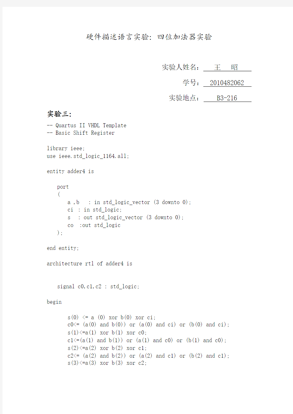
VHDL四位加法器实验报告

- 1、下载文档前请自行甄别文档内容的完整性,平台不提供额外的编辑、内容补充、找答案等附加服务。
- 2、"仅部分预览"的文档,不可在线预览部分如存在完整性等问题,可反馈申请退款(可完整预览的文档不适用该条件!)。
- 3、如文档侵犯您的权益,请联系客服反馈,我们会尽快为您处理(人工客服工作时间:9:00-18:30)。
硬件描述语言实验:四位加法器实验
实验人姓名:王昭
学号: 2010482062
实验地点: B3-216 实验三:
-- Quartus II VHDL Template
-- Basic Shift Register
library ieee;
use ieee.std_logic_1164.all;
entity adder4 is
port
(
a ,
b : in std_logic_vector (3 downto 0);
ci : in std_logic;
s : out std_logic_vector (3 downto 0);
co :out std_logic
);
end entity;
architecture rtl of adder4 is
signal c0,c1,c2 : std_logic;
begin
s(0) <= a (0) xor b(0) xor ci;
c0<= (a(0) and b(0)) or (a(0) and ci) or (b(0) and ci);
s(1)<=a(1) xor b(1) xor c0;
c1<=(a(1) and b(1)) or (a(1) and c0) or (b(1) and c0);
s(2)<=a(2) xor b(2) xor c1;
c2<= (a(2) and b(2)) or (a(2) and c1) or (b(2) and c1);
s(3)<=a(3) xor b(3) xor c2;
co<= (a(3) and b(3)) or (a(3) and c2) or (b(3) and c2);
end rtl;
实验原理:
a和b为两个四位的数,定义三个信号量,c0,c1,c2;低位进位si=0;
s(0)=a(0)+b(0)+si;进位为c0;
s(1)=a(1)+b(1)+c0;进位为c1;
s(2)=a(2)+b(2)+c1;进位为c2;
s(3)=a(3)+b(3)+c2;进位为co;
低位进位si都为0;
如果a+b的值大于15时,则co为1,s=a+b-16;
如果不是大于15,则相加时则s=a+b的值,co=0;经仿真可以验证此四位加法器正确。
实验四:
-- Quartus II VHDL Template
-- Basic Shift Register
library ieee;
use ieee.std_logic_1164.all;
use ieee.std_logic_unsigned.all;
entity adder4_2 is
port
(
a,b : std_logic_vector(3 downto 0);
ci : in std_logic;
s :out std_logic_vector(3 downto 0);
co : out std_logic
);
end entity;
architecture rtl of adder4_2 is
signal aa,bb,ss:std_logic_vector(4 downto 0);
begin
aa<='0'& a;
bb<='0'& b;
ss<=aa+bb+ci;
s <= ss(3 downto 0);
co<=ss(4);
end rtl;
实验分析:此实验与上一实验功能相同,但此实验代码中运用了高层次抽象行为描述,直接使用了现实中使用的加法运算。
定义了aa,bb,ss三个信号量,来存储a,b,s的值,通过aa<=’0’&a 把四位的a和b变成五位。来实现ss=aa+bb+si;最终把ss的低四位赋给s;ss的高位赋给co;便实现了四位加法器。
观察仿真图,可以发现,si=0;因为最低位没有最低进位,通过高层次抽象行为描述直接把aa(4 downto 0)+bb(4 downto 0)的和赋给ss,把ss(3 downto 0)赋给s ,co=ss(4);
从仿真图上看出来,计算正确。此四位加法器正确。
实验八:
-- Quartus II VHDL Template
-- Basic Shift Register
library ieee;
use ieee.std_logic_1164.all;
entity adder4_3 is
port
(
A,B : in std_logic_vector(3 downto 0);
Ci : in std_logic;
S : out std_logic_vector(3 downto 0);
Co : out std_logic
);
end entity;
architecture full of adder4_3 is
component full_adder is
port
(
a : in std_logic;
b : in std_logic;
ci : in std_logic;
s,co : out std_logic
);
end component;
signal c0,c1,c2: std_logic;
begin
u0:full_adder port map(A(0),b(0),Ci,S(0),c0);
u1:full_adder port map(A(1),B(1),c0,S(1),c1);
u2:full_adder port map(A(2),B(2),c1,S(2),c2);
u3:full_adder port map(A(3),B(3),c2,S(3),Co);
end full;
实验分析:
此实验是通过一位加法器来实现的四位加法器,一位加法器的代码如下:
library ieee;
use ieee.std_logic_1164.all;
entity full_adder is
port
