1756机架
ControlLogix
O K
Processor
Output Module
AC OUTPUT
1 5 11 11 13 15 0 1 2 3 4 5 6 7 8 910 12 14 11 13 15 0 1 2 3 4 5 6 7 8 910 12 14
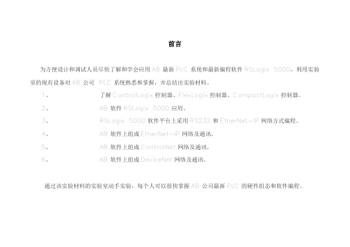
I/O 数据能在控制器和/或操作员界面设备之间共享 I/O共享为构造系统提供更大的灵活性
Logix5550
RUN I/O RS232 BAT OK
O K
0
7
15
RUN
REM
PROG
DIAGNOSTIC
Rockwell Automation Internal
Ethernet
ControlNet
PRODUCER/CONSUMER I/O
背板及网络通讯
• 基于通讯的模块化框架 – 目前 - Ethernet, ControlNetTM DH+, RIO, DeviceNetTM, 串口 (控制器),串行模板, Modbus, Profibus – 将来 - DH485,DCS-Net 等 – 混合和匹配网络界面 – 根据需求增减网络 灵活的网络 – 支持网络间桥接和路由功能 – 支持调度的I/O, 对等通讯, 和非调度的信息传输 – 无需处理器 支持 I/O共享 可组态软件
Rockwell Automation Internal
处理器内存
1756-Mx (Logix5550) • 1756-M1---512KB • 1756-M2---1MKB • 1756-M3---2MKB
1756-M1x (Logix5555) •1756-M13---1.5MB •1756-M14---3.5MB •1756-M16---7.5MB
ControlNet网络控制远程IO
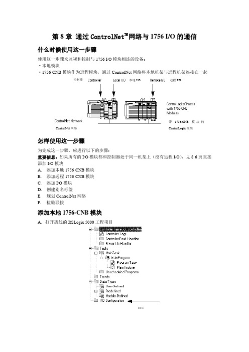
第8章 通过ControlNet TM网络与1756 I/O 的通信什么时候使用这一步骤使用这一步骤来监视和控制与1756 I/O 模块相连的设备:·本地模块·1756-CNB模块作为远程模块,通过ControlNet 网络将本地机架与远程机架连接在一起怎样使用这一步骤为完成这一步骤,应进行以下的步骤:重要信息:如果所有的I/O 模块都和控制器处于同一机架上(没有远程I/O ),见8-6页直接添加I/O 模块 A. 添加本地1756-CNB 模块 B. 添加远程1756-CNB 模块 C. 添加I/O 模块 D.创建别名标签E. 规划ControlNet 网络F. 检验联接添加本地1756-CNB 模块A .打开离线的RSLogix 5000工程项目带1756-CNB 模块的ControlLogix 框架ControlNet 网络控制器本地I/O远程I/OB. 右键点击I/O Configuration 并选择New Module 。
C. 选择CNB 模块的类型并点击OK 。
D. 为该模块键入一个名称(如name_of_local_cnb )。
E. 填写并选择模块所安装的槽号。
F .安装在该槽的任意模块与下表里匹配信息的接近程度G .点击Next 。
H .最初,是否想让模块与控制器进行通信?禁止一个模块利用禁止模块检查栏,使它很容易的测试一个系统⏹ 最初,禁止该模块。
⏹ 当准备测试与模块相连结的设备时,清除检查栏。
I .如果与模块通讯失败,想让控制器做出怎样的反应?如果与模块通讯失败,控制器就会用模块的原来数据进行操作。
为了避免潜在的伤害和损坏,当通讯出现错误时,与模块通讯的 监控器或组态模块都会产生一个主要错误。
J .点击Finis h.添加远程1756-CNB 模块A . 右键点击 name_of_local_cnb 并选择 New Module . B. 选择远程机架上的CNB 的类型,并单击OK 。
多功能天车SLC500控制系统和人机界面的升级改造
预焙阳极铝电解工艺生产,可完成打壳、更换阳极、
类型,研究多功能天车运行控制逻辑,制定多功能
覆盖氧化铝和电解质、槽上部氟化盐加料、吊运阳
天车控制系统和人机界面升级改造方案,对原控制
极母线提升框架、吊运上部机构和下部槽壳、完成
系统和人机界面硬件更换升级并重新编写控制程
厂房零星吊运和维修作业。
序和画面。
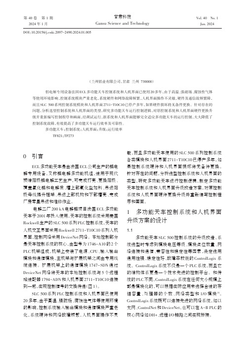
电解二厂 200 kA 电解铝项目法国 ECL 多功能
个将各信号线拆下来接到新的模块接线端子上,接
完所有控制线后再仔细复核一下接线是否正确。
2.3
编程
根据 ControlLogix 系列 PLC RS Logix5000 编程
第 1 期
杨永刚:多功能天车 SLC500 控制系统和人机界面的升级改造
23
规范和指令,对照天车原 SLC 500 程序编写 Contr-
1794- 1794- 1794ADN IE8 IB16
节点 33
EB/DNET
1747-SDN
1746-OW16
1746-OW16
1746-OW16
1746-OW16
1746-OW16
1746-P2
DeviceNet 网络
节点 19
人机界面
2711-T10C10
光纤
EB/DNET
机架型号 1746-A10
22
甘
科
第 40 卷
技
1756-DNB
1756-ENBT
1756-IB16I
1756-IB16I
1756-IB16I
以太网交
换机
UT-6405
全向发射
装置
VS-TR-58
N1C2 柜
RSLogix5000 入门

RSLogix5000 入门运行“开始\所有程序\Rockwell Software \RSLogix 5000 Enterprise Series \RSLogix5000 ”或双击桌面上RSLogix 5000 的图标,打开RSLogix 5000软件。
1 从File菜单选择New,显示New Controller对话框。
2 从Type的下拉菜单中选择1756-L62(或1756-L55) ControlLogix Controller。
3 在Revision的下拉菜单中选择13。
4 在Name栏中键入字母和数字组合作为处理器的名字,如Test1。
5 从Chassis Type下拉菜单中选择1756-A10 10-Slot ControlLogix Chassis。
(机架槽数还可能为7槽或13槽此时请对应选择1756-A7 7-Slot ControlLogix Chassis或1756-A13 13-Slot ControlLogix Chassis)6 在Slot Number栏内选择0,与机架中的控制器模块的位置匹配。
7 在Create In栏内键入文件保存路径或点击Browse键定位地址目录,我们创建文件目录在C:\RSLogix 5000\Projects\ 。
8 确认输入与图1-2所示吻合,然后点击OK。
由此创建了一个控制器文件。
左侧菜单是控制程序的主体架构Controller Organizer,控制器组织画面由文件夹项目树和文件组成,文件中包含现在这个控制器文件中有关程序和数据的所有信息。
各部分说明如下:Controller File Name –包括控制器范围的标签、控制器故障处理程序和电源处理程序。
Tasks –在这个文件夹中显示任务,每个任务都有各自带梯形图例程和程序范围标签的程序。
Trends –在这个文件夹中创建趋势图。
Data Type –显示预定义和用户定义的数据类型,用户定义的数据在这个文件夹中创建。
rslogix5000软件介绍
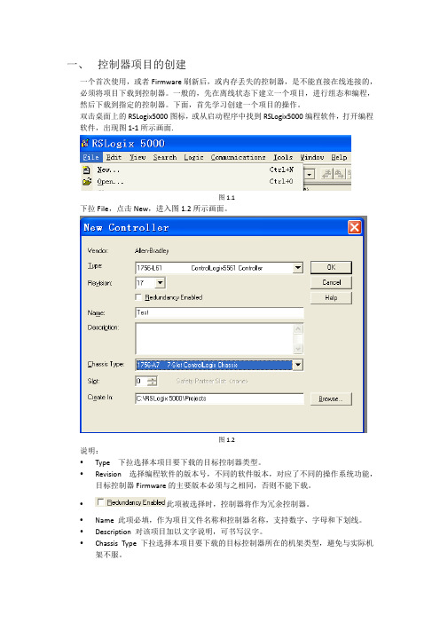
一、 控制器项目的创建一个首次使用,或者Firmware刷新后,或内存丢失的控制器,是不能直接在线连接的,必须将项目下载到控制器。
一般的,先在离线状态下建立一个项目,进行组态和编程,然后下载到指定的控制器。
下面,首先学习创建一个项目的操作。
双击桌面上的RSLogix5000图标,或从启动程序中找到RSLogix5000编程软件,打开编程软件,出现图1‐1所示画面.图1.1下拉File,点击New,进入图1.2所示画面。
图1.2说明:y Type 下拉选择本项目要下载的目标控制器类型。
y Revision 选择编程软件的版本号,不同的软件版本,对应了不同的操作系统功能,目标控制器Firmware的主要版本必须与之相同,否则不能下载。
y此项被选择时,控制器将作为冗余控制器。
y Name 此项必填,作为项目文件名称和控制器名称,支持数字、字母和下划线。
y Description 对该项目加以文字说明,可书写汉字。
y Chassis Type 下拉选择本项目要下载的目标控制器所在的机架类型,避免与实际机架不服。
y Slot 指定本项目要下载的目标控制器在机架中所在槽的位置。
y Create In 指定本项目的磁盘存储文件在磁盘中的存放路径,默认值在C:\RSLogix 5000\Projects,亦可自行确定。
点击OK,进入如图1.3所示画面。
图1.3至此,一个项目被创建。
二、 本地I/O模块的建立和监控在I/O Configuration下,选中1756的背板,右击,选中New Module,出现下图所示画面。
1756机架可插放的模块在这里都能找到,亦可分类选择。
(1)数字量输入/输出模块的建立和监控数字量模块有8点、16点和32点之分,有交流和直流之分,有隔离和非隔离之分,模块用途各异,外端接线不同,不过组态过程是相似的。
点击New Module后,出现如下图所示画面。
由于要添加的是数字量模块,选择将Digital前的“+”展开,选择1756‐IB16D,这是一个16点24VDC输入模块带诊断功能,双击该模块,出现下图所示画面。
AB-PLC及网络通讯培训教程
前言为方便设计和调试人员尽快了解和学会应用AB最新PLC系统和最新编程软件RSLogix 5000,利用实验室的现有设备对AB公司 PLC系统熟悉和掌握,并总结出实验材料。
1、了解ControlLogix控制器、FlexLogix控制器、CompactLogix控制器。
2、AB软件RSLogix 5000应用。
3、RSLogix 5000软件平台上采用RS232和EtherNet-IP网络方式编程。
4、AB软件上组成EtherNet-IP网络及通讯。
5、AB软件上组成ControlNet网络及通讯。
6、AB软件上组成DeviceNet网络及通讯。
通过该实验材料的实验室动手实验,每个人可以很快掌握AB公司最新PLC的硬件组态和软件编程。
第一节硬件和软件介绍一、根据实验室模板熟悉AB公司PLC各系列模块1)PLC5大型(实验室无此硬件)2)SLC5003)LOGIX系列CompactLogixFlexLogixControlLogixDriveLogixSoftLogix4)POINT I/O,远程分站I/O.内容:1)查看各模块的外形,通讯模块,I/O模块,处理器模块等。
2)ControlLogix框架式设计可靠,安装容易,无需工具。
端子可取下,接线方便,更换快速。
主要以此系列PLC作为培训内容3)可带电热插拔。
安装方便。
4)有多种网络通讯模块二、配套软件名称1)通讯平台软件:RSLinx;2)Logix系列PLC编程软件:RSLogix5000;3)网络规划软件(控制网):RSNetWorx for ControlNet;4)网络规划软件(以太网):RSNetWorx for EtherNet-IP;5)网络规划软件(设备网):RSNetWorx for DeviceNet;6)上位机软件:RSView32;7)PenelViewPlus触摸屏软件:RSView Studio for SE(ME);三、硬件和软件的版本(见表)表一、软件版本号表二、CPU硬件版本号1、对于硬件主要考虑CPU和通讯模块的硬件版本号。
AB-1756模块状态检查
现场模块指示灯状态及四字指示器显示内容1756-L6系列CPU指示灯:序号指示图案名称颜色状态描述1 运行指示灯(RUN)关闭控制器在编程或测试模式将控制器运行模式改为RUN;绿色控制器在运行模式不需要操作;2 I/O指示灯关闭1、控制器IO组态中没有添加设备;2、程序中没有工程,内存为空;1、添加需要的设备;2、下载工程;绿色闪烁控制器IO组态中的一个或多个设备没有响应;程序上线并检查控制器的IO组态;绿色控制器与所有的IO正常通讯;不需要操作;红色闪烁机架损坏;更换机架;3 FORCE指示灯关闭没有强制的标签或强制功能被禁止;不需要操作;琥珀色IO强制功能被激活;小心应用,添加强制后会立刻生效;琥珀色闪烁一个或多个I/O地址被强制为ON或OFF,但强制未被使能;小心应用,强制使能后强制IO会立刻生效;4 RS232指示灯关闭未被激活;不需要操作;绿色数据正在被发送或接收;不需要操作;5 红/绿闪烁自检状态模块正在执行上电自检;1756CNBR 常见状态RACK ERR 由于EEPROM初始化失败或故障造成模块不能读取存储在EEPROM中的数据长度;更换机架;CNP2 ERR 由于固件问题造成网络KEEPER不可用;升级固件或将这个模块的地址调至2或更大;BPIC ERR 硬件故障更换模块;检查机架是否损坏;CNIC ERR 硬件故障更换模块;检查机架是否损坏;红色闪烁ROM UPDT 固件正在升级;不需要操作;DUPL NODE 节点地址重复;重设一个网络中唯一的节点地址;BOOT 固件升级失败;升级固件;绿色OK 正常运行;不需要操作;绿色或绿闪BPA# ERR模块检查到一个不同于上电时的槽地址,过多的背板噪声造成这个错误;确定系统有良好的接地;重新上电;移除模块,确定背板连接器是否损坏;BPRX ERR由于过多的CRC故障产生导致背板的多点接收器已经关闭;重新上下电或重启模块;更换模块;KPR ERRKEEPER错误导致模块不能正常工作;检查模块所在网络;重新规划网络;BW XCED模块繁忙或连接超时;网络带宽超出;不需要操作;如果现象频繁发生则添加另一块通讯模块;红色闪烁NET ERR 网络电缆故障或没有其它网络节点;检查网络电缆并确定网络上有其它活动的节点;2 A和B状态指示灯全部关闭无电源接通电源稳定的红色有故障的模块对模块重新上电或联系厂家处理;红/绿闪烁自检不需要操作;红闪错误的节点配置检查CNBR的节点地址和其它模块的参数配1756-CNBR 模块状态指示器和显示器1756-CNBR 的网络信道状态指示器1757-SRM模块屏状态显示1757-SRM模块正常状态指令1757-SRM模块通讯状态指令1757-SRM模块机架状态指令1757-SRM模块故障标准和显示信息。
RockwellABPLC基础培训入门篇
Rockwell AB PLC 基础培训入门篇,7天熟悉AB PLC系统开发第一篇AB的PLC产品长期以来一直被认为最可靠、最高端的PLC产品,产品的质量和性能为世界顶级,AB品牌属于美国ROCKWELL公司,其生产的PLC2(可能很多人并不知道,P LC5知道的人很多,在之前还有PLC2,PLC3产品)产品目前在世界上仍然有很多地方继续在工作。
AB的PLC大致可以分如下几类:1.Logix平台产品,细分如下:ControlLogix、CompactLogix、FlexLogix该系列产品全部采用Logix5000软件进行编程组态2.SLC500平台产品SLC500、MicroLogix该系列产品全部采用Logix500软件进行编程组态3.PLC5,PLC3,PLC2等老产品PLC5采用RsLogix5软件进行编程组态,某些老的型号采用DOS版6200软件进行编程PLC3,PLC2采用DOS版6200软件进行编程组态其中PLC2有几款第3方开发的编程软件,全运行在DOS环境下由于PLC5等产品非目前主流产品,正在逐步被淘汰,因此本文不将其作为讨论的主要内容。
RsLinx技术介绍:RsLinx软件为ROCKWELL产品提供了统一的通讯平台,是进行编程的必要软件之一。
RsLinx软件根据六个版本分为:RSLinx Lite、RSLinx Single Node、RSLinx OEM、RSLinx P rofessional、RSLinx Gateway、RSLinx SDK。
版本在RSLinx OEM以后的4个版本均支持开发OPC应用程序或C-API客户程序,并在RSLinx S DK中包括了开发OPC应用程序或C-API客户程序的技术资料。
标准版,Lite版本,此版本为免费版本,仅支持PLC编程通讯专业版,Professional版本,提供了OPC DDE SERVER功能,可以作为组态软件的通讯驱动,并且支持RSLINX C API开发的应用程序或驱动OEM版,单节点版,很少见,名如其意,也能支持OPC DDE SERVER网关版,Gateway版本,比专业版本增加了Remote 远程访问的能力,如远程OPC等。
ControlLogix-XT ControlNet 接口模块安装指南说明书
安装指南ControlLogix-XT ControlNet 接口模块产品目录号 1756-CN2RXT主题页码重要用户须知2关于 ControlLogix-XT ControlNet 模块7关于 ControlLogix-XT 系统9带传统 ControlLogix 组件的 ControlLogix-XT9使用 1756-CN2RXT 实现独立或冗余控制10冗余 ControlLogix-XT 系统实例11开始之前的工作11部件12设置模块的网络地址12将模块复位到初始出厂设置13准备安装模块要使用的机架14确定模块插槽位置14电热插拔 (RIUP)15安装 ControlNet 模块15将模块连接到网络17取出模块20安装 EDS 文件21组态 RSLinx 软件来使用 USB 端口22安装 USB 驱动程序23状态指示器24模块状态指示灯和显示器24通道状态指示灯30通用技术参数 - 1756-CN2RXT32环境规范 - 1756-CN2RXT33认证 - 1756-CN2RXT35其它资源362ControlLogix-XT ControlNet 接口模块重要用户须知固态设备具有与机电设备不同的运作特性。
Safety Guidelines for the Application, Installation and Maintenance of Solid State Controls (固态控制设备的应用、安装与维护安全指南,出版号:SGI-1.1,可向您当地的罗克韦尔自动化销售处索取或通过在线索取) 描述了固态设备和硬接线机电设备之间的一些重要区别。
由于存在这些区别,同时由于固态设备的广泛应用,负责应用此设备的所有人员都必须确保仅以可接受的方式应用此设备。
对于由于使用或应用此设备而导致的任何间接损失或连带损失,罗克韦尔自动化在任何情况下都不承担任何责任。
本手册中的示例和图表仅供说明之用。
ABPLC培训硬件组态培训
4、创立(chuànglì)标签(Create tags)
5、输入逻辑(Enter logic)
6、下载工程(Download a project)〔包括
从控制器读取工程〕
7、检查形状(View status)〔包括检查I/O
缺点〕
第十二页,共68页。
创立(chuànglì)工程
第十三页,共68页。
第九页,共68页。
ControlLogix 5000编程软件(ruǎn jiàn)
RSLogix5000软件的功用: 1、自在-格式的梯形图编辑器,它运用户在书写顺
序时可以专心于运用顺序的逻辑而不用留意语法 的对错。 2、强有力的工程校验器。用户可用其创立错误清 单,从而可以在方便的时分修正。 3、拖放式编辑功用。 4、查询和交流功用。可以快速改动特定地址(dìzhǐ) 或符号的值 5、工程目录为点击式界第十页面,共68页。。 用户可访问包括在工
第二十三页,共68页。
组态(zǔ tài)本地机架
e〕 ENBT通讯模块(mókuài)位于第2号槽〔确认一下〕,按以以下图所示内容填 写, 按OK。
第二十四页,共68页。
组态(zǔ tài)远程机架
2、接上去中止远程机架的I/O组态 a〕 CNB通讯模块。鼠标左键点击1756-CNB/D CNB1〔CNB1模块,位于左边窗口的
5.6W 5.6W
208K字节 无
5.7W
208K字节 无
6.3W
208K字节 有
5.6W
208K字节 有
5.6W
208K字节 有
5.7W
478K字节 Compactflash卡+ 3.5W
478K字节 Compactflash卡+ 3.5W
- 1、下载文档前请自行甄别文档内容的完整性,平台不提供额外的编辑、内容补充、找答案等附加服务。
- 2、"仅部分预览"的文档,不可在线预览部分如存在完整性等问题,可反馈申请退款(可完整预览的文档不适用该条件!)。
- 3、如文档侵犯您的权益,请联系客服反馈,我们会尽快为您处理(人工客服工作时间:9:00-18:30)。
Technical Data1756 ControlLogix Chassis SpecificationsCatalog Numbers 1756-A4/B, 1756-A4K/B, 1756-A4/C, 1756-A4K/C, 1756-A7/B, 1756-A7K/B, 1756-A7/C, 1756-A7K/C, 1756-A10/B, 1756-A10K/B, 1756-A10/C, 1756-A10K/C, 1756-A13/B, 1756-A13K/B, 1756-A13/C, 1756-A13K/C, 1756-A17/B, 1756-A17K/B, 1756-A17/C, 1756-A17K/C, 1756-A4LXT/B, 1756-A5XT/B, 1756-A7LXT/B, 1756-A7XT/B, 1756-A7XT/CThe ControlLogix® system is a modular system that requires a 1756 ControlLogix chassis. The chassis are designed for only horizontal back-panel mounting. Place any module into any slot. The backplane provides a high-speed communication path between modules.AutoCAD product drawings are available at /en/e-tools/drawings.html .TopicPage Standard ControlLogix Chassis Specifications 2ControlLogix-XT Chassis Specifications 4Spacing Requirements6ControlLogix Chassis with Standard Power Supplies Mounting Dimensions (Series B)8ControlLogix Chassis with Standard Power Supplies Mounting Dimensions (Series C)12ControlLogix Chassis Accessories 20Additional Resources211756 ControlLogix Chassis SpecificationsStandard ControlLogix Chassis SpecificationsThe chassis backplane provides a high-speed communication path between modules and distributes power to each of the modules within the chassis.Table 1 - Technical Specifications - ControlLogix Standard Chassis (Series B)Attribute1756-A4/B1756-A7/B1756-A10/B1756-A13/B1756-A17/B Backplane current, chassis/slot max @ 1.2V DC 1.5 A/-Backplane current, chassis/slot max @ 3.3V DC 4 A/4 ABackplane current, chassis/slot max @ 5.1V DC15 A/6 ABackplane current, chassis/slot max @ 24V DC 2.8 A/2.8 APower dissipation, max 4 W 4.5 W 5 W 5.4 W 6 WIsolation voltage Determined by installed power supply and modulesSlots47101317Mounting method Only horizontalCabinet size (HxWxD), min50.8 x 50.8 x 20.3 cm(20 x 20 x 8 in.)50.8 x 60.9 x 20.3 cm(20 x 24 x 8 in.)50.8 x 76.2 x 20.3 cm(20 x 30 x 8 in.)60.9 x 76.2 x 20.3 cm(24 x 30 x 8 in.)76.2 x 91.4 x 20.3 cm(30 x 36 x 8 in.)Weight, approx0.75 kg (1.7 lb) 1.10 kg (2.4 lb) 1.45 kg (3.2 lb) 1.90 kg (4.2 lb) 2.20 kg (4.8 lb) Location PanelWire size Functional Earth Ground - 8.3 mm2 (8 AWG) solid or stranded copper wire rated at 90 °C (194 °F) or greaterProtective Earth Ground - 2.1 mm2 (14 AWG) solid or stranded copper wire rated at 90 °C (194 °F) or greaterNorth American temperature code T5IEC temperature code T4T5Enclosure type rating None (open-style)Table 2 - Technical Specifications - ControlLogix Standard Chassis (Series C)Attribute1756-A4/C1756-A7/C1756-A10/C1756-A13/C1756-A17/C Backplane current, chassis/slot max @ 1.2V DC 1.5 A/-Backplane current, chassis/slot max @ 3.3V DC 4 A/4 ABackplane current, chassis/slot max @ 5.1V DC15 A/6 ABackplane current, chassis/slot max @ 24V DC 2.8 A/2.8 APower dissipation, max 4 W 4.5 W 5 W 5.4 W 6 W Isolation voltage Determined by installed power supply and modulesSlots47101317 Mounting method Only horizontalCabinet size (HxWxD), min50.8 x 50.8 x 20.3 cm(20 x 20 x 8 in.)50.8 x 60.9 x 20.3 cm(20 x 24 x 8 in.)50.8 x 76.2 x 20.3 cm(20 x 30 x 8 in.)60.9 x 76.2 x 20.3 cm(24 x 30 x 8 in.)76.2 x 91.4 x 20.3 cm(30 x 36 x 8 in.)Weight, approx0.75 kg (1.7 lb) 1.10 kg (2.4 lb) 1.45 kg (3.2 lb) 1.90 kg (4.2 lb) 2.20 kg (4.8 lb) Location PanelWire size Functional earth ground - 8.3 mm2 (8 AWG) solid or stranded copper wire rated at 90 °C (194 °F) or greaterProtective earth ground - 2.1 mm2 (14 AWG) solid or stranded copper wire rated at 90 °C (194 °F) or greaterNorth American temperature code T4IEC temperature code T4Enclosure type rating None (open-style)2Rockwell Automation Publication 1756-TD006E-EN-E - October 20141756 ControlLogix Chassis Specifications Table 3 - Environmental Specifications - ControlLogix Standard ChassisAttribute1756-A4/B, 1756-A7/B, 1756-A10/B, 1756-A13/B,1756-A17/B 1756-A4/C, 1756-A7/C, 1756-A10/C, 1756-A13/C, 1756-A17/CTemperature, operatingIEC 60068-2-1 (Test Ad, Operating Cold),IEC 60068-2-2 (Test Bd, Operating Dry Heat),IEC 60068-2-14 (Test Nb, Operating Thermal Shock)0…60 °C (32…140 °F)-25…60 °C (-13…140 °F)Temperature, surrounding air60 °C (140 °F)Temperature, nonoperatingIEC 60068-2-1 (Test Ab, Unpackaged Nonoperating Cold),IEC 60068-2-2 (Test Bb, Unpackaged Nonoperating Dry Heat),IEC 60068-2-14 (Test Na, Unpackaged Nonoperating Thermal Shock)-40…85 °C (-40…185 °F)Relative humidityIEC 60068-2-30 (Test Db, Unpackaged Damp Heat)5…95% noncondensingVibrationIEC 60068-2-6 (Test Fc, Operating)2 g @ 10…500 HzShock, operatingIEC 60068-2-27 (Test Ea, Unpackaged Shock)30 gShock, nonoperatingIEC 60068-2-27 (Test Ea, Unpackaged Shock)50 g30 gEmissions IEC 61000-6-4ESD immunity IEC 61000-4-26 kV contact discharges 8 kV air dischargesRadiated RF immunity IEC 61000-4-310V/m with 1 kHz sine-wave 80% AM from 80…2000 MHz 10V/m with 200 Hz 50% Pulse 100% AM @ 900 MHz10V/m with 200 Hz 50% Pulse 100% AM @ 1890 MHz3V/m with 1 kHz sine-wave 80% AM from 2000…2700 MHzTable 4 - Certifications - ControlLogix Standard ChassisCertification(1)1756-A4/B1756-A7/B, 1756-A10/B, 1756-A13/B, 1756-A17/B1756-A4/C, 1756-A7/C, 1756-A10/C, 1756-A13/C,1756-A17/Cc-UL-us UL Listed Industrial Control Equipment, certified for US and Canada. See UL File E65584.UL Listed for Class I, Division 2 Group A,B,C,D Hazardous Locations, certified for U.S. and Canada. See UL File E194810.CSA CSA Certified Process Control Equipment. See CSA File LR54689C.CSA Certified Process Control Equipment for Class I, Division 2 Group A,B,C,D Hazardous Locations. See CSA FileLR69960C.CSA Certified Process Control Equipment. See CSA File LR054689.CSA Certified Process Control Equipment for Class I, Division 2 Group A,B,C,D Hazardous Locations. See CSA FileLR069960.FM FM Approved Equipment for use in Class I Division 2 Group A,B,C,D Hazardous Locations. CE European Union 2004/108/EC EMC Directive, compliant with:•EN 61326-1; Meas./Control/Lab., Industrial Requirements•EN 61000-6-2; Industrial Immunity•EN 61000-6-4; Industrial Emissions•EN 61131-2; Programmable Controllers (Clause 8, Zone A & B)RCM Australian Radiocommunications Act, compliant with:EN 61000-6-4; Industrial EmissionsEx European Union 94/9/EC ATEX Directive, compliant with:•EN 60079-15; Potentially Explosive Atmospheres,Protection “n”•EN 60079-0; General Requirements•II 3 G Ex nA IIC T4 Gc X European Union 94/9/EC ATEX Directive, compliant with:•EN 60079-15; Potentially Explosive Atmospheres,Protection “n”•EN 60079-0; General Requirements•II 3 G Ex nA IIC T5 Gc XEuropean Union 94/9/EC ATEX Directive, compliant with:•EN 60079-15; Potentially Explosive Atmospheres,Protection “n”•EN 60079-0; General Requirements•II 3 G Ex nA IIC T4 Gc•DEMKO13ATEX1325026XRockwell Automation Publication 1756-TD006E-EN-E - October 201434Rockwell Automation Publication 1756-TD006E-EN-E - October 20141756 ControlLogix Chassis SpecificationsControlLogix-XT Chassis SpecificationsThe ControlLogix-XT™ chassis support extreme temperature environments. The chassis are conformally coated for increased survivability in ISA G3 environments.IECExN/AIECEx System, compliant with:•IEC 60079-15; Potentially Explosive Atmospheres, Protection "n"•IEC 60079-0; General Requirements •II 3 G Ex nA IIC T4 Gc •IECExUL14.0008XKC Korean Registration of Broadcasting and Communications Equipment, compliant with:Article 58-2 of Radio Waves Act, Clause 3EACRussian Customs Union TR CU 020/2011 EMC Technical Regulation Russian Customs Union TR CU 004/2011 LV Technical Regulation(1)See the Product Certification link at for Declarations of Conformity, Certificates, and other certification details.Table 5 - Technical Specifications - ControlLogix-XT ChassisAttribute1756-A4LXT/B 1756-A7LXT/B1756-A5XT/B1756-A7XT/B1756-A7XT/CBackplane current, chassis/slot max @ 1.2V DC 1.5 A/-Backplane current, chassis/slot max @ 3.3V DC 4 A/4 A Backplane current, chassis/slot max @ 5.1V DC 10 A/6 A 15 A/6 A 10 A/6 A Backplane current, chassis/slot max @ 24V DC 2 A/2 A 2.8 A/ 2.8A2 A/2 APower dissipation, max 3.7 W4.1 W4.4 WIsolation voltage Determined by installed power supply and modules Slots4757Mounting method Horizontal only Cabinet size (HxWxD), min 50.8 x 50.8 x 20.3 cm (20 x 20 x 8 in.)50.8 x 60.9 x 20.3 cm (20 x 24 x 8 in.)50.8 x 76.2 x 20.3 cm (20 x 30 x 8 in.)50.8 x 60.9 x 20.3 cm (20 x 24 x 8 in.)Weight, approx 0.75 kg (1.7 lb) 1.1 kg (2.4 lb)1.45 kg (3.2 lb)1.09 kg (2.4 lb)Location PanelWire sizeFunctional earth ground - 8.3 mm 2 (8 AWG) solid or stranded copper wire rated at 90 °C (194 °F) or greater Protective earth ground - 2.1 mm 2 (14 AWG) solid or stranded copper wire rated at 90 °C (194 °F) or greater North American temperature code T5T4AT4IEC temperature code T5T4Enclosure type ratingNone (open-style)Table 4 - Certifications - ControlLogix Standard ChassisCertification (1)1756-A4/B 1756-A7/B, 1756-A10/B, 1756-A13/B, 1756-A17/B1756-A4/C, 1756-A7/C, 1756-A10/C, 1756-A13/C, 1756-A17/CRockwell Automation Publication 1756-TD006E-EN-E - October 201451756 ControlLogix Chassis SpecificationsTable 6 - Environmental Specifications - ControlLogix-XT ChassisAttribute1756-A4LXT/B, 1756-A7LXT/B 1756-A5XT/B, 1756-A7XT/B 1756-A7XT/CTemperature, operatingIEC 60068-2-1 (Test Ad, Operating Cold),IEC 60068-2-2 (Test Bd, Operating Dry Heat),IEC 60068-2-14 (Test Nb, Operating Thermal Shock)-25…60 °C (-13…140 °F)-25…70 °C (-13…158 °F)Temperature, surrounding air60 °C (140 °F)70 °C (158 °F)Temperature, nonoperatingIEC 60068-2-1 (Test Ab, Unpackaged Nonoperating Cold),IEC 60068-2-2 (Test Bb, Unpackaged Nonoperating Dry Heat),IEC 60068-2-14 (Test Na, Unpackaged Nonoperating Thermal Shock)-40…85 °C (-40…185 °F)Relative humidityIEC 60068-2-30 (Test Db, Unpackaged Damp Heat)5…95% noncondensing VibrationIEC 60068-2-6 (Test Fc, Operating) 2 g @ 10…500 Hz Shock, operatingIEC 60068-2-27 (Test Ea, Unpackaged Shock)30 g Shock, nonoperatingIEC 60068-2-27 (Test Ea, Unpackaged Shock)50 g 30 gEmissions IEC 61000-6-4ESD immunity IEC 61000-4-2 6 kV contact discharges 8 kV air dischargesRadiated RF immunity IEC 61000-4-310V/m with 1 kHz sine-wave 80% AM from 80…2000 MHz 10V/m with 200 Hz 50% Pulse 100% AM @ 900 MHz 10V/m with 200 Hz 50% Pulse 100% AM @ 1890 MHz3V/m with 1 kHz sine-wave 80% AM from 2000…2700 MHzTable 7 - Certifications - ControlLogix-XT ChassisCertification (1)(1)See the Product Certification link at for Declarations of Conformity, Certificates, and other certification details.1756-A5XT/B, 1756-A7XT/B, 1756-A7XT/C1756-A4LXT/B, 1756-A7LXT/Bc-UL-us UL Listed Industrial Control Equipment, certified for US and Canada. See UL File E65584.UL Listed for Class I, Division 2 Group A,B,C,D Hazardous Locations, certified for U.S. and Canada. See UL File E194810.FM FM Approved Equipment for use in Class I Division 2 Group A,B,C,D Hazardous Locations.CEEuropean Union 2004/108/EC EMC Directive, compliant with:•EN 61326-1; Meas./Control/Lab., Industrial Requirements •EN 61000-6-2; Industrial Immunity •EN 61000-6-4; Industrial Emissions•EN 61131-2; Programmable Controllers (Clause 8, Zone A & B)RCM Australian Radiocommunications Act, compliant with: EN 61000-6-4; Industrial EmissionsExEuropean Union 94/9/EC ATEX Directive, compliant with:•EN 60079-15; Potentially Explosive Atmospheres, Protection “n”•EN 60079-0; General Requirements •II 3 G Ex nA IIC T4 Gc X •DEMKO13ATEX1325026XIECExIECEx System, compliant with:•IEC 60079-15; Potentially Explosive Atmospheres, Protection "n"•IEC 60079-0; General Requirements •II 3 G Ex nA IIC T4 Gc •IECExUL14.0008XIECEx System, compliant with:•IEC 60079-15; Potentially Explosive Atmospheres, Protection "n"•IEC 60079-0; General Requirements •II 3 G Ex nA IIC T5 Gc •IECExUL14.0008X KC Korean Registration of Broadcasting and Communications Equipment, compliant with:Article 58-2 of Radio Waves Act, Clause 3EACRussian Customs Union TR CU 020/2011 EMC Technical Regulation Russian Customs Union TR CU 004/2011 LV Technical Regulation6Rockwell Automation Publication 1756-TD006E-EN-E - October 20141756 ControlLogix Chassis SpecificationsSpacing RequirementsWhen you mount a ControlLogix chassis with a standard power supply in an enclosure, follow these spacing requirements(series C chassis depicted).Dimensions are in cm (in.).The 10.2 (4.0) measurement to the side of the enclosure can include the wireway.Rockwell Automation Publication 1756-TD006E-EN-E - October 201471756 ControlLogix Chassis SpecificationsWhen you mount a ControlLogix chassis with a redundant power supply and a chassis adapter in an enclosure, follow these spacing requirements (series C chassis depicted).Series C chassis offer:•Improved slot guidelines •Improved ventilation •Stronger mounting tabs•Additional hole in mounting tab •Additional ground screwIMPORTANTThe 1756-CPR2 cable has a bend radius of 12.7 cm (5.0 in.). The chassis must have a minimum clearance of 12.7 cm (5.0 in.) on the left side to route and connect the 1756-CPR2 cable. The redundant power supplies must have a minimum clearance of 12.7cm (5.0 in.) below the supply to route and connect the 1756-CPR2 cable.Dimensions are in cm (in.).The 10.2 (4.0) measurement to the side of the enclosure can include the wireway only on the right side of the chassis.8Rockwell Automation Publication 1756-TD006E-EN-E - October 20141756 ControlLogix Chassis SpecificationsControlLogix Chassis with Standard Power Supplies Mounting Dimensions (Series B)Dimensions are in cm (in.).Figure 1 - Chassis Common DimensionsFigure 2 - 1756-A4/B Chassis and Power SupplyTop Mounting Hole DiameterBottom Mounting Hole DiameterRight-side View of All Standard ChassisRight-side View of All ControlLogix-XT Chassis0.557.0 4.711756 ControlLogix Chassis Specifications Figure 3 - 1756-A7/B Chassis and Power SupplyFigure 4 - 1756-A10/B Chassis and Power Supply5.7Figure 5 - 1756-A13/B Chassis and Power Supply5.7Rockwell Automation Publication 1756-TD006E-EN-E - October 201491756 ControlLogix Chassis SpecificationsFigure 6 - 1756-A17/B Chassis and Power Supply4.7Figure 7 - 1756-A4LXT/B Chassis and Power Supply7.0 6.3Figure 8 - 1756-A5XT/B Chassis and Power Supply7.310Rockwell Automation Publication 1756-TD006E-EN-E - October 20141756 ControlLogix Chassis Specifications Figure 9 - 1756-A7LXT/B Chassis and Power SupplyFigure 10 - 1756-A7XT/B Chassis and Power Supply1756 ControlLogix Chassis SpecificationsControlLogix Chassis with Standard Power Supplies Mounting Dimensions (Series C)Dimensions are in cm (in.).Figure 11 - Chassis Common DimensionsFigure 12 - 1756-A4/C Chassis and Power SupplyTop Mounting Bottom Mounting Right-side View of All Standard ChassisRight-side View of All ControlLogix-XT Chassis0.557.0 4.711756 ControlLogix Chassis SpecificationsFigure 13 - 1756-A7/C Chassis and Power SupplyFigure 14 - 1756-A10/C Chassis and Power SupplyFigure 15 - 1756-A13/C Chassis and Power Supply4.715.75.71756 ControlLogix Chassis SpecificationsFigure 16 - 1756-A17/C Chassis and Power Supply4.7Figure 17 - 1756-A7XT/C Chassis and Power Supply7.31756 ControlLogix Chassis SpecificationsControlLogix Chassis with Redundant Power Supplies Mounting Dimensions (Series B)Dimensions are in cm (in.).Figure 18 - Redundant Power SuppliesFigure 19 - Chassis Common DimensionsIMPORTANTThe 1756-CPR2 cable has a bend radius of 12.7 cm (5.0 in.). The chassis must have a minimum clearance of 12.7 cm (5.0 in.) on the left side to route and connect the 1756-CPR2 cable. The redundant power supplies must have a minimum clearance of 12.7cm (5.0 in.) below the supply to route and connect the 1756-CPR2 cable.Top Mounting Hole DiameterBottom Mounting 7.0Top Mounting Tab DiameterBottom Mounting Tab DiameterRight-side View of All Chassis1756 ControlLogix Chassis SpecificationsFigure 20 - 1756-A4/B Chassis and Chassis Adapter Module7.0 4.7Figure 21 - 1756-A7/B Chassis and Chassis Adapter ModuleFigure 22 - 1756-A10/B Chassis and Chassis Adapter Module5.711756 ControlLogix Chassis SpecificationsFigure 23 - 1756-A13/B Chassis and Chassis Adapter ModuleFigure 24 - 1756-A17/B Chassis and Chassis Adapter Module.Figure 25 - 1756-A4LXT/B Chassis and Chassis Adapter5.714.76.297.01756 ControlLogix Chassis SpecificationsFigure 26 - 1756-A5XT/A7XT/B Chassis and Chassis Adapter7.31756 ControlLogix Chassis SpecificationsControlLogix Chassis with Redundant Power Supplies Mounting Dimensions (Series C)Figure 27 - Redundant Power SuppliesFigure 28 - Chassis Common DimensionsIMPORTANTThe 1756-CPR2 cable has a bend radius of 12.7 cm (5.0 in.). The chassis must have a minimum clearance of 12.7 cm (5.0 in.) on the left side to route and connect the 1756-CPR2 cable. The redundant power supplies must have a minimum clearance of 12.7cm (5.0 in.) below the supply to route and connect the 1756-CPR2 cable.Top Mounting Hole DiameterBottom Mounting 7.0Top Mounting Tab DiameterBottom Mounting Tab DiameterRight-side View of All Chassis(0.31)0.55 (0.217)1756 ControlLogix Chassis SpecificationsFigure 29 - 1756-A7XT/C Chassis and Chassis AdapterControlLogix Chassis AccessoriesUse a slot filler module to fill empty slots.Cat. No.Description1756-N2Slot filler module for empty slots in standard ControlLogix chassis 1756-N2XTSlot filler module for empty slots in ControlLogix-XT chassis7.31756 ControlLogix Chassis Specifications Additional ResourcesThese documents contain additional information concerning related products from Rockwell Automation.Resource DescriptionControlLogix Selection Guide, publication1756-SG001Provides an overview of the ControlLogix system and its products.ControlLogix Power Supplies Specifications Technical Data, publication 1756-TD005Provides technical specifications for ControlLogix power supplies.ControlLogix System User Manual, publication 1756-UM001Provides information on how to install, configure, program, and use ControlLogix controllers. Industrial Automation Wiring and Grounding Guidelines, publication 1770-4.1Provides general guidelines for installing a Rockwell Automation® industrial system. Product Certifications website, Provides declarations of conformity, certificates, and other certification details.Y ou can view or download publications at /literature/. T o order paper copies of technical documentation, contact your local Allen-Bradley® distributor or Rockwell Automation sales representative.Rockwell Automation Publication 1756-TD006E-EN-E - October 2014211756 ControlLogix Chassis SpecificationsNotes:22Rockwell Automation Publication 1756-TD006E-EN-E - October 20141756 ControlLogix Chassis Specifications Rockwell Automation Publication 1756-TD006E-EN-E - October 201423Allen-Bradley, ControlLogix, ControlLogix-XT, Rockwell Software, Rockwell Automation, and LISTEN. THINK. SOLVE are trademarks of Rockwell Automation, Inc.T rademarks not belonging to Rockwell Automation are property of their respective companies.Publication 1756-TD006E-EN-E - October 2014Supersedes Publication 1756-TD006D-EN-E - March 2013Copyright © 2014 Rockwell Automation, Inc. All rights reserved. Printed in the U.S.A.Important User InformationRead this document and the documents listed in the additional resources section about installation, configuration, and operation of this equipment before you install, configure, operate, or maintain this product. Users are required tofamiliarize themselves with installation and wiring instructions in addition to requirements of all applicable codes, laws, and standards.Activities including installation, adjustments, putting into service, use, assembly, disassembly, and maintenance are required to be carried out by suitably trained personnel in accordance with applicable code of practice.If this equipment is used in a manner not specified by the manufacturer, the protection provided by the equipment may be impaired.In no event will Rockwell Automation, Inc. be responsible or liable for indirect or consequential damages resulting from the use or application of this equipment.The examples and diagrams in this manual are included solely for illustrative purposes. Because of the many variables and requirements associated with any particular installation, Rockwell Automation, Inc. cannot assume responsibility or liability for actual use based on the examples and diagrams.No patent liability is assumed by Rockwell Automation, Inc. with respect to use of information, circuits, equipment, or software described in this manual.Reproduction of the contents of this manual, in whole or in part, without written permission of Rockwell Automation, Inc., is prohibited.Documentation FeedbackY our comments will help us serve your documentation needs better. If you have any suggestions on how to improve this document, complete this form, publication RA-DU002, available at /literature/.Rockwell Otomasyon Ticaret A.Ş., Kar Plaza İş Merkezi E Blok Kat:6 34752 İçerenköy, İstanbul, T el: +90 (216) 5698400。