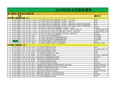
2012.06.03日AC-20热料仓筛分
聚氯乙烯╱聚乙烯╱聚偏二氯乙烯固体药用复合硬片
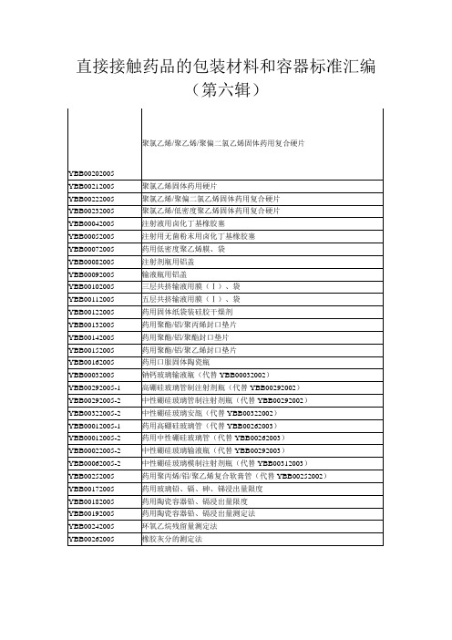
(1)膜 按每卷膜取2米进行检验;
(2)袋 按计数抽样检验程序 第1部分:按接受质量限(AQL)检索的逐批抽样计划(GB/T2828.1-2003)规定进行。检查水平为一般检查水平Ⅱ,接受质量限(AQL)为6.5。
药用低密度聚乙烯膜、袋质量标准的起草说明
一、概况
根据国家食品药品监督管理局下发的"关于下发2005年药包材标准制(修)定工作计划的函"[食药监注函[2005] 3号],制定该标准。
(2)密度取本品约2g,浸渍液选用无水乙醇,照密度测定法(YBB00132003)测定,
本品的密度应为0.910~0.935g/cm3。
【阻隔性能】水蒸气透过量除另有规定外,取本品适量,照水蒸气透过量测定法(YBB00092003) 第一法 杯式法测定,试验温度(38±0.6)℃,相对湿度(90±2)%,不得过15g/(m224h)。
7、异常毒性 采用中国药典的方法,应符合规定。
国家食品药品监督管理局
国家药品包装容器(材料)标准
(试行)
YBB00082005
注射剂瓶用铝盖
Zhushejipingyong Lügai
Caps made of aluminium for Injection
本标准适用于注射剂瓶用铝盖。
【外观】 取铝盖适量,在自然光线明亮处目测,应清洁,无残留润滑剂、毛刺和损伤。
YBB00142005
药用聚酯/铝/聚酯封口垫片
YBB00152005
药用聚酯/铝/聚乙烯封口垫片
YBB00162005
药用口服固体陶瓷瓶
YBB00032005
钠钙玻璃输液瓶(代替YBB00032002)
YBB00292005-1
新疆国信准东电厂锅炉技术协议

新疆国信准东2X660MW煤电项目工程超临界空冷燃煤机组锅炉技术协议买方:新疆国信煤电能源有限公司卖方:上海电气集团股份有限公司设计方:西北电力设计院2013年 5 月上海目录附件1 技术规范 (1)附件2 供货范围 (85)附件3 技术文件和图纸交付进度 (106)附件4 交货进度 (114)附件5 监造、检验和性能验收试验 (116)附件6 技术服务与设计联络 (126)附件7 分包商与外购部件情况 (131)附件8 大件部件情况 (132)附件1 技术规范1.0 总则1.0.1 本技术协议适用于新疆国信准东2X660MW煤电项目工程超临界间接空冷燃煤机组的锅炉设备,它提出设备的功能设计、结构、性能、安装和试验等方面的技术要求。
1.0.2 买方在本技术协议中提出了最低限度的技术要求,并未规定所有的技术要求和适用的标准,卖方应提供一套满足本技术协议和所列标准要求的高质量产品及其相应服务。
对国家有关安全、环保等强制性标准,应满足其要求。
1.0.3 卖方应执行本技术协议所列标准,如有矛盾时,按最新的高标准执行。
1.0.4 删除1.0.5 技术协议签订后2个月内,按本技术协议要求,卖方提出合同设备的设计、制造、检验/试验、装配、安装、调试、试运、验收、试验、运行和维护等标准清单给买方,由买方确认。
1.0.6 卖方对成套设备(含辅助系统与设备)负有全部技术及质量责任,包括分包(或采购)的设备和零部件。
对于分包设备和主要外购零部件,卖方必须推荐3家合格的分包商,技术上由卖方全面负责归口和协调,分包商最终由买方确定。
1.0.7 在签订合同之后,买方有权提出因规范、标准和规程发生变化而产生的一些补充要求,在设备投料生产前,卖方应在设计上给予修改。
具体项目由招投标双方共同商定。
1.0.8 本工程全面采用KKS编码标识系统,要求卖方提供的所有技术文件(包括图纸)采用KKS编码标识系统(卖方应承诺执行买方提供的企业标准定义的编码原则和方法,深度和内容满足工程设计要求)。
ASTM标准中英文对照
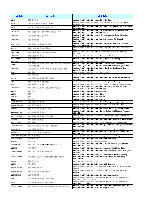
Standard Specification for Structural Steel for Ships Standard Specification for Ferromolybdenum Standard Specification for Pipe, Steel, Electric-Fusion (Arc)-Welded (Sizes NPS 16 and Over) Standard Specification for Electric-Resistance-Welded Steel Pipe Standard Specification for Electric-Fusion (Arc)-Welded Steel Pipe (NPS 4 and Over) Standard Practice for Safeguarding Against Embrittlement of Hot-Dip Galvanized Structural Steel Products and Procedure for Detecting Embrittlement Specification for Ferrotungsten Standard Specification for Molybdenum Oxide Products Standard Specification for Steel Castings, High Strength, for Structural Purposes Standard Specification for Zinc Coating (Hot-Dip) on Iron and Steel Hardware Standard Specification for Automotive Gray Iron Castings Standard Specification for Stainless and Heat-Resisting Chromium-Nickel Steel Plate, Sheet, and Strip Standard Specification for Stainless and Heat-Resisting Chromium Steel Plate, Sheet, and Strip Standard Specification for Electric-Resistance-Welded Carbon Steel and Carbon-Manganese Steel Boiler and Superheater Tubes
ES标准
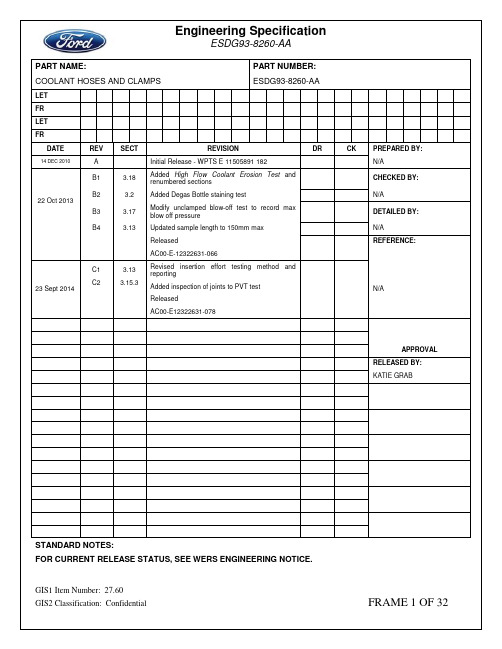
PART NAME:COOLANT HOSES AND CLAMPS PART NUMBER: ESDG93-8260-AALETFRLETFRDATE REV SECT REVISION DR CK PREPARED BY: 14 DEC 2010 A Initial Release - WPTS E 11505891 182 N/A22 Oct 2013 B1 3.18Added High Flow Coolant Erosion Test andrenumbered sectionsCHECKED BY: B2 3.2 Added Degas Bottle staining test N/AB3 3.17Modify unclamped blow-off test to record maxblow off pressureDETAILED BY: B4 3.13 Updated sample length to 150mm max N/AReleasedAC00-E-12322631-066REFERENCE:23 Sept 2014 C1C23.133.15.3Revised insertion effort testing method andreportingAdded inspection of joints to PVT testReleasedAC00-E12322631-078N/AAPPROVALRELEASED BY:KATIE GRABSTANDARD NOTES:FOR CURRENT RELEASE STATUS, SEE WERS ENGINEERING NOTICE.CONTROL ITEM –IDENTIFIES CRITICAL CHARACTERISTICS DESIGNATED BY THE CROSS FUNCTIONAL1. GENERALThe purpose of this specification is to define the functional engineering requirements of a rubber hose assembly.This specification is a supplement to the released drawing, and all requirements must be met. Exceptions to this specification are not permitted.SAFETY NOTE: The test procedures in this specification are specifically designed to evaluate rubber hoseassembly performance and durability failure mechanisms. Temperature and pressure extremes, mechanical loading, and chemical exposure are all used to create simulated hose assembly failures. The testing facility is responsible to ensure all required laboratory safety precautions are followed.2. SUMMARY OF DESIGN VERIFICATION, PRODUCTION VALIDATION, AND IN-PROCESS TESTINGDesign Verification (DV) tests verify the design meets functional engineering requirements. DV testing completion, and Ford Product Development Engineering approval of Design Verification Plan and Report (DVPR), is required prior to any design being approved for production tooling.Production Validation (PV) tests validate the production manufacturing process produces parts as designed. PV testing completion, and Ford Product Development Engineering approval of Production Validation Plan and Report (PVPR), is required prior to any manufacturing process being approved for production.In-Process (IP) tests ensure the production manufacturing process remains capable and stable. Ford Product Development Engineering approval of manufacturing process control plan, and associated In-Process Testing Plan, is required prior to any manufacturing process being approved for production. IP testing is also commonly known as Continuing Conformance (CC) testing.All sample sizes defined in this specification are minimum required per part number. Ford may require increased PV quantity, and / or increased IP quantity, and / or increased IP frequency after manufacturing process and control plan review. Any test plan, including use of surrogate data or additional test quantities to ensure statisticalconformance, must be approved by Ford Product Development Engineering. Any sample size identified as"Testing not required", only implies conformance testing demonstration is not required. "Testing not required" does not permit acceptance criteria nonconformance. Ford reserves the right to require acceptance criteriaconformance demonstration testing at any time.DV, PV, and IP sample size, acceptance criteria, and statistical conformance are summarized in Table 1.Table 1. Test summary provided as reference only. See specific test for complete details and requirements.Test NameDVSampleSizePVSampleSizeIPSampleSizeAcceptance CriteriaStatisticalConformance SECTION A: HOSE CONSTRUCTION – REINFORCED HOSES3.1Burst, Swell, and ImpulseTesting per WSE-M96D34- A2/A3/A46 for anyinternalrequirements6 for anyinternalrequirements(For Burst and Swell,DV may besubmitted for PV withapproval from FordEngineering)NR•See Specification for acceptancecriteria.See specification forconformance criteria.3.2Physical Properties and Staining Potential – Hose per WSE-M96D34- A2/A3/A46 for anyinternalrequirements6 for anyinternalrequirements(DV may besubmitted for PV withapproval from FordEngineering)NR•See Specification for acceptancecriteria.See specification forconformance criteria.3.3Physical Properties – Wire perASTM A-2276 for anyinternalrequirements6 for anyinternalrequirementsNR•See Specification for acceptancecriteria.See specification forconformance criteria.3.4Corrosion Resistance – Wireper ASTM B-1176 for anyinternalrequirements6 for anyinternalrequirementsNR•See Specification for acceptancecriteria.See specification forconformance criteria.SECTION B: CLAMPS3.5Clamp dimensions, material, heat treat, and performance per WK902 Worldwide Fastener Standard6 for anyinternalrequirements6 for anyinternalrequirementsNR•See Specification for acceptancecriteria.See specification forconformance criteria.3.6Clamp Corrosion Protection perWSS-M21P45-A1/A26 for anyinternalrequirements6 for anyinternalrequirementsNR •See Specification for acceptancecriteria.See specification forconformance criteria.3.7 Horizontal Clamp Adhesion tothe Hose with Pull Off Test 630 per clampdiameter perglue stationNR•The clamp must withstand333N without de-bondingthe glue and degrading thehose material.All samplesmeet theacceptancecriteria3.8 Radial Clamp Adhesion ReturnTest6 6 NR•Clamp must return to theoriginal position within +/-10 degrees.All samplesmeet theacceptancecriteria3.9 Clamp Glue Strength- HighTemperature 6 6 NR •Insertion efforts to lessthan those defined withinprovided Ford Hose JointMatrix.•No visible leaks duringtesting.•No visible damage ofhoses.All samplesmeet theacceptancecriteria3.10 Clamp Glue Dissociation- HighTemperature 6 6 NR•Inspect hoses for anydamage (pitting) after hosehas been removed.•Glue, plating and rubberresidue permissible.All samplesmeet theacceptancecriteria3.11 Clamp Glue De-bonding 6 6 NR •Clamp must de-bond withno degradation of the hosematerial.•Glue, plating and rubberresidue permissible.All samplesmeet theacceptancecriteriaSECTION C: COMPLETE HOSE ASSEMBLIES3.12 Hose DimensionalRequirements 6 30 6 parts per startof each run (tobe captured inControl Plan)•All ID, OD, wall thickness,and wall variabilitydimensions must adhereto the tolerances as shownon the drawing and have acpk of at least 1.33.All samplesmeet theacceptancecriteria3.13 Hose Insertion Efforts 15 15 NR •The force required toinsert the hose onto a tubemust not exceed ERGOtargets.All samplesmeet theacceptancecriteria3.14 Wet Leak / Blow Off Test 6 (+1) 6 NR•The coolant hoseassembly must not leak atless than 1.2 times themaximum operatingpressure or 248kPa,whichever is greater. Thecoolant hose must notblow-off or separate atless than 1.5 times themaximum operatingpressure.All samplesmeet theacceptancecriteria3.15 PVT/Durability(Pressure, Vibrations &Temperature)6 6 NR•Test assemblies mustcomplete 28,000 pressurecycles with no noticeablecoolant leakage.All samplesmeet theacceptancecriteria3.16 Air Under Water Test 6 6 NR •The coolant hoseassembly must not leak orseparate at less than 248kPa.•Failure is visible airbubbles under the water orseparation of the hosefrom tube.All samplesmeet theacceptancecriteria3.17 Unclamped Air Blow-off TestNR 3 NR •For information only•Record maximium blow-offpressure on HJOINTtemplate.All samplesmeet theacceptancecriteria3.18 High Flow Coolant Erosion Test(Glass fiber reinforced nyloncomponents with orifice smallerthan 10mm diameter) 3 3 NR•The coolant hoseassembly must not leak orseparate at less than 248kPa (36 psi). Failure isvisible air bubbles underthe water.•The change in pressuredrop may not vary by morethan 5% or by the amountcalled out on theengineering drawing.All samplesmeet theacceptancecriteriaSECTION D: COMPLETE HOSE ASSEMBLIES WITH BRANCHED PORTIONS3.19 Pullout Test(Branched Hose assembly)6 per eachbranch of hose6 per eachbranch of hoseNR•The minimum applied loadshould be no less than102 kg.•The hose should pass thistest without any failures.All samplesmeet theacceptancecriteria3.20 Pressure Cycling(Branched Hose assembly) 6 per cavity 6 per cavityNR•50,000 cycles minimummust be achieved withoutfailure, where failure isdefined as burst, visibleleak or deformation.All samplesmeet theacceptancecriteriaSECTION E: GENERAL REQUIREMENTS3.21 Hose Requirements NR NR NR •To be included within thePPAP packaged. All samples meet the acceptance criteria3.22 Identification NR NR NR •To be included within thePPAP package. All samples meet the acceptance criteria3. SECTION A: HOSE CONSTRUCTION TEST PROCEDURES AND ACCEPTANCE CRITERIA3.2.6. Reporting•All test reports must include all measurements, photographs, and data files as defined in procedure.•All test reports must include all laboratory notes and test observation log sheets.•DV test report must be provided to Ford in electronic format with DVPR submission.•PV test report must be provided to Ford in electronic format with PVPR submission.•IP test reports not required.3.3. Physical Properties – Wire per ASTM A-2273.3.1. Instrumentation•Refer to instrumentation required within specification ASTM A-227.3.3.2. Procedure•Refer to procedure within specification ASTM A-227.X3.3.3. Acceptance Criteria•Refer to the acceptance criteria required within specification ASTM A-227.3.3.4. Sample Size•DV: (6) for any internal requirements within the specification ASTM A-227.•PV: (6) for any internal requirements within the specification ASTM A-227.•IP: Not required.3.3.5. Statistical Conformance•Refer to conformance criteria within the specification ASTM A-227.3.3.6. Reporting•All test reports must include all measurements, photographs, and data files as defined in procedure.•All test reports must include all laboratory notes and test observation log sheets.•DV test report must be provided to Ford in electronic format with DVPR submission.•PV test report must be provided to Ford in electronic format with PVPR submission.•IP test reports not required.3.4. Corrosion Resistance – Wire per ASTM B-1173.4.1. Instrumentation•Refer to instrumentation required within specification ASTM B-117.3.4.2. Procedure•Refer to procedure within the specification ASTM B-117.3.4.3. Acceptance Criteria•Refer to the acceptance criteria within the specification ASTM B-117.X3.4.4. Sample Size•DV: (6) for any internal requirements within the specification ASTM B-117.•PV: (6) for any internal requirements within the specification ASTM B-117.•IP: Not required.3.4.5. Statistical Conformance•Refer to conformance criteria within the specification ASTM B-117.3.4.6. Reporting•All test reports must include all measurements, photographs, and data files as defined in procedure.•All test reports must include all laboratory notes and test observation log sheets.•DV test report must be provided to Ford in electronic format with DVPR submission.•PV test report must be provided to Ford in electronic format with PVPR submission.•IP test reports not required.3. SECTION B: CLAMP TEST PROCEDURES AND ACCEPTANCE CRITERIAClamp Retention Method – GluingGluing is the only approved method of clamp retention for pre-opened pre-positioned constant tensionhose clamps (POPP-CTHC). A glued POPP clamp must meet, at a minimum, the followingperformance specifications.The POPP clamp must be glued on the hose at the final assembly position. Glue location is 180degrees opposite the installation tangs of the clamps, as shown below. Clamp location to the end ofthe hose must be specified on the assembly drawing.3.5. Clamp Dimensions, Material, Heat Treat, and Performance per WK9023.5.1. Instrumentation•Refer to instrumentation required within specification WK902.3.5.2. Procedure•Refer to procedure within specification WK902.3.5.3. Acceptance Criteria•Refer to acceptance criteria required within specification WK902.3.5.4. Sample Size•DV: (6) for any internal requirements within the specification WK902.•PV: (6) for any internal requirements within the specification WK902.•IP: Not required.3.5.5. Statistical Conformance•Refer to conformance criteria within the specification WK902.3.5.6. Reporting•All test reports must include all measurements, photographs, and data files as defined in procedure.•All test reports must include all laboratory notes and test observation log sheets.•DV test report must be provided to Ford in electronic format with DVPR submission.•PV test report must be provided to Ford in electronic format with PVPR submission.•IP test reports not required.3.6. Clamp Corrosion Protection per WSS-M21P45-A1/A23.6.1. Instrumentation•Refer to instrumentation required within specification WSS-M21P45-A1/A2.3.6.2. Procedure•Refer to procedure within specification WSS-M21P45-A1/A2.3.6.3. Acceptance Criteria•Refer to acceptance criteria within specification WSS-M21P45-A1/A2.•DV: (6) for any internal requirements within the specification WSS-M21P45-A1/A2.•PV: (6) for any internal requirements within the specification WSS-M21P45-A1/A2.•IP: Not required.3.6.5. Statistical Conformance•Refer to conformance criteria within the specification WSS-M21P45-A1/A2.3.6.6. Reporting•All test reports must include all measurements, photographs, and data files as defined in procedure.•All test reports must include all laboratory notes and test observation log sheets.•DV test report must be provided to Ford in electronic format with DVPR submission.•PV test report must be provided to Ford in electronic format with PVPR submission.•IP test reports not required.3.7. Horizontal Clamp Adhesion to the Hose with Pull Off Test (Destructive)3.7.1. Instrumentation•Fixture to properly secure sample during test procedure.•Must be capable of measuring the pull off force of at least 445N (100 lbf).•The clamps must be production representative and glued onto the hose per the Engineering drawing.3.7.2. Procedure•Install hose assembly in a vise from 100 to 150mm (4 to 6 inches) of the hose end.•Attach force test equipment 180 degrees from the glued surface.•Pull clamp parallel to the hose centerline with a rate of 100 – 130 mm/minute (4 – 5 inches/minute).•Apply force until at least 333N (75lbf) without de-bonding the glue and degrading the hose material.•Continue to apply force until de-bonding occurs. Note force value at which this event occurs.3.7.3. Acceptance Criteria•The clamp must withstand 333N without de-bonding the glue and/or degrading the hose material.•DV: 6•PV: 30 per diameter per glue station•IP: Not required.3.7.5. Statistical Conformance•There is no statistical conformance for this requirement. All samples must meet the acceptance criteria.3.7.6. Reporting•All test reports must include all measurements, photographs, and data files as defined in procedure.•All test reports must include all laboratory notes and test observation log sheets.•DV test report must be provided to Ford in electronic format with DVPR submission.•PV test report must be provided to Ford in electronic format with PVPR submission.•IP test reports not required.3.8. Radial Clamp Adhesion Return Test (non-Destructive)3.8.1. Instrumentation•Fixture to properly secure sample during test procedure.•Force gauges capable of measuring the full of force of at least 445N (100 lbf).•The clamps must be production representative and glued onto the hose per the Engineering drawing.3.8.2. Procedure•Install hose assembly in a vise from 100 to 150mm (4 to 6 inches) of the hose end.•Attach force test equipment 180 degrees from the glued surface.•Rotate clamp radially in either direction 45 degrees and hold for one minute.•Remove test equipment from clamp and allow clamp to recover to its natural position for one minute.3.8.3. Acceptance Criteria•Clamp must return to the original position within +/- 10 degrees.•DV: 6•PV: 6•IP: Not required.3.8.5. Statistical Conformance•There is no statistical conformance for this requirement. All samples must meet the acceptance criteria.3.8.6. Reporting•All test reports must include all measurements, photographs, and data files as defined in procedure.•All test reports must include all laboratory notes and test observation log sheets.•DV test report must be provided to Ford in electronic format with DVPR submission.•PV test report must be provided to Ford in electronic format with PVPR submission.•IP test reports not required.3.9. Clamp Glue Strength– High Temperature (Destructive)3.9.1. Instrumentation•Production intent ports required for each hose joint as defined in Ford Hose Joint Matrix.•Oven capable of reaching temperatures of 70±3°C.•Force gauges to measure maximum insertion efforts for hose installation.•The clamps must be production representative and glued onto the hose per the drawing.3.9.2. Procedure•Heat oven to 70±3°C.•Place hoses within oven for a minimum of 24 hrs.•Remove the hoses from the oven and allow them to cool to ambient 23±3C.•Mark a visible line along the clamp and hose, parallel to the center line of the hose over the middle of the glue patch. This line will be used as reference to determine if the clamp has moved relative to thehose during the release process.•Install heat aged hoses onto production intent ports, and release the clamps with a standard screwdriver with a tip width of 5±1mm and force applied a distance of 17±4 cm.3.9.3. Acceptance Criteria•Clamp must not de-bond (spin freely) from hose during the hose assembly and clamp release process.The reference line on the hose relative to the reference line on the clamp must be within 15 degrees.•No visible damage of hoses.3.9.4. Sample Size•DV: 6•PV: 6•IP: Not required.3.9.5. Statistical Conformance•There is no statistical conformance for this requirement. All samples must meet the acceptance criteria.3.9.6. Reporting•All test reports must include all measurements, photographs, and data files as defined in procedure.•All test reports must include all laboratory notes and test observation log sheets.•DV test report must be provided to Ford in electronic format with DVPR submission.•PV test report must be provided to Ford in electronic format with PVPR submission.•IP test reports not required.3.10. Clamp Glue Dissociation – High Temperature (Destructive)3.10.1. Instrumentation•Oven capable of reaching temperatures of 85±3°C.•Tools capable to removing the clamps without damaging hoses.•The clamps must be production representative and glued onto the hose per the drawing.3.10.2. Procedure•Heat oven to 85±3°C.•Place coolant hoses within oven for 6 hours ± 30 minutes.•Remove the hoses from the oven and allow to cool to ambient.•Remove clamps from hoses.3.10.3. Acceptance Criteria•The adhesion must dissociate to a level where the clamp can be removed without damaging (delamination / pitting) greater than 0.5mm from the surface of the hose material.•Glue, plating, and/or minor rubber residue is permissible.3.10.4. Sample Size•DV: 6•PV: 6•IP: Not required.3.10.5. Statistical Conformance•There is no statistical conformance for this requirement. All samples must meet the acceptance criteria.3.10.6. Reporting•All test reports must include all measurements, photographs, and data files as defined in procedure.•All test reports must include all laboratory notes and test observation log sheets.•DV test report must be provided to Ford in electronic format with DVPR submission.•PV test report must be provided to Ford in electronic format with PVPR submission.•IP test reports not required.3.11. Clamp Glue De-bonding (Destructive)3.11.1. Instrumentation•Heat gun capable of temperatures of at least 218°C.•The clamps must be production representative and glued onto the hose per the drawing.3.11.2. Procedure•Apply heated air 204-218°C to glued area of clamp for maximum of 2 minutes.•Manually remove clamp(s) from hose.3.11.3. Acceptance Criteria•Clamp must de-bond with no degradation of the hose material.•No rubber residue on the clamp is permissible.•No clamp coating residue on the hose is permissible.3.11.4. Sample Size•DV: 6•PV: 6•IP: Not required.3.11.5. Statistical Conformance•There is no statistical conformance for this requirement. All samples must meet the acceptance criteria.3.11.6. Reporting•All test reports must include all measurements, photographs, and data files as defined in procedure.•All test reports must include all laboratory notes and test observation log sheets.•DV test report must be provided to Ford in electronic format with DVPR submission.•PV test report must be provided to Ford in electronic format with PVPR submission.•IP test reports not required.3. SECTION C: TEST PROCEDURES AND ACCEPTANCE CRITERIA (COMPLETE HOSEASSEMBLIES)3.12. Hose Dimensional Requirements (Non-Destructive)3.12.1. Instrumentation•To determine acceptability of the hose I.D., hose O.D. and wall thickness, wall variability and groove depth dimensions. Measurements are to be made on all PV and IP samples.•Lotis QC-20 (or equivalent) non-contact measurement device3.12.2. Procedure•Measurements are to be taken within 25mm (1 inch) distance from end of hose and after forming processes and prior to gluing clamps to hoses.•Record ID, OD, wall thickness, wall variability, and groove depth for each end of the hose samples.NOTE: ID measurements taken using a non-contact method of measurement will typically yield smallervalues than traditional contact measurement methods (ie, plug gages). As a result, opticalmeasurement data for hose ID should be divided by a correction factor of 0.9894 prior to reportingresults.Alternative process for In-Process measurements of ID, OD, wall thickness, and wall variabilityonly: if non-contact measurement equipment is not available (or for diameters that fall outsideof the capabilities of the non-contact measurement device) for on-going IP measurements,traditional measurement devices (plug gages, pi tape, calipers) may be used. The preferredcontact method of measurement is as follows:•Use a pin / plug gage to determine the actual I.D. of the hose.•Leaving the (actual I.D.) plug gage inserted, use a pi tape to measure the (average) O.D. of the hose.•With the plug gage still inserted, use calipers to determine the maximum and minimum (local) O.D. of the hose.•Remove the plug gage and use a snap gage (or equivalent) to measure the wall thickness in at least six different areas around the perimeter of the hose. Use care to include the apparent thickest andthinnest areas of the hose wall.•Subtract the smallest reading from the largest - the difference to determine the range of wall thickness variability.3.12.3. Acceptance Criteria•All ID, OD, wall thickness, and wall variability dimensions must adhere to the tolerances as shown on the drawing and have a cpk of at least 1.33.•Axial groove depth due to reinforcement material on the ID must not exceed an average of 0.16mm AND no individual measurement shall exceed 0.26mm at any time.3.12.4. Sample Size•DV: 6•PV: 30•IP: 6 parts per start of each run.3.12.5. Statistical Conformance•DV: 15•PV: 15•IP: Not required.3.13.5. Statistical Conformance•No individual peak force measurement shall exceed 1.2 times the maximum acceptable insertion targets cascaded by the appropriate Ford Ergonomics Engineer.3.13.6. Reporting•Record the push-on force for each hose on the Hose Joint Matrix.•Retain the insertion Force curves for each sample.•All test reports must include all measurements, photographs, and data files as defined in procedure.•All test reports must include all laboratory notes and test observation log sheets.•Report results generated from universal testing machine (tensile / compression). Report must include bench test values as well as values corrected for application of wiggle method.•All test reports must include all measurements, photographs, and data files as defined in procedure.•DV test report must be provided to Ford in electronic format with DVPR submission.•PV test report must be provided to Ford in electronic format with PVPR submission.•IP test reports not required.3.14. Wet Leak / Blow Off Test (Destructive)3.14.1. Instrumentation•Test Fixture must be capable of pressures of at least 1034 kPag (150 psig) at a rate of 34.5 kPag/sec(5 psig/sec).•Test assemblies should be evaluated in an enclosed test stand.•The spigot / fitting(s) must be production representative.•The clamps must be production representative and glued onto the hose per the drawing.3.14.2. Procedure•Measure all hose samples per 3.12 Hose Dimensional Requirements prior to test.•Measure the spigot / fitting used at the bead and 3 locations along the land length: (1) immediately behind the bead, (2) at the center of the land length, and (3) immediately in front of the hose stop.Sufficient measurements shall be taken around the spigot at each location in order to determine theminimum and maximum diameters at each location. If the land length is not smooth (ie ridges orriblets present) then both major and minor diameters must be measured at each of the three locationsalong the land length.•The resulting interference fit (connector land OD – hose ID) for the parts being used for testing must be within +/-0.1mm of the intended nominal dimension per the hose and spigot drawings. If thecalculated interference stack-up resides outside of the +/- 0.1mm window, then the appropriate FordEngineer shall be contacted for further direction.•The samples shall be allowed to stabilize at standard laboratory test temperature for 1 hour after assembly.•Using either water or 50/50 engine coolant/water mixture, apply pressure at a rate not to Exceed 34.5 kPa/sec (5 psi/sec) up to a maximum of 1034 kPa (150 psi).•Observe and document any movement or leakage of the joint along with corresponding pressures during the test.•After all hoses have been tested with production intent clamps, secure one of the hoses to the production representative connectors with a slotted screw clamp (as used in service). Apply torqueuntil visible damage to the hose / clamp occurs or 5.7Nm (~50in-lbs), whichever is less. Then repeatthe pressure test and re-measure the connector and report any damage to the connector due to theclamp load applied to the joint.3.14.3. Acceptance Criteria•The coolant hose assembly must not leak (ie, no visible fluid) at less than 1.2 times the maximum operating pressure or 248kPag (36psig), whichever is greater. The coolant hose must not blow-off orseparate at less than 1.5 times the maximum operating pressure.•The single hose joint secured with a screw clamp must not leak or separate at less than 1.5 times the maximum operating pressure. The tube shall not be dimensionally distorted enough to cause failure ofthe joint (leakage or blow-off).3.14.4. Sample Size•DV: 6 (+1 for screw clamp)•PV: 6•IP: Not required.3.14.5. Statistical Conformance•There is no statistical conformance for this requirement. All samples must meet the acceptance criteria.3.14.6. Reporting•All test reports must include all measurements, photographs, and data files as defined in procedure.•All test reports must include all laboratory notes and test observation log sheets.•If no leakage occurs below 1034 kPag (150 psig), then state "pass at 1034 kPag (150 psig)".•If leakage and/or blow-off occurs below 1034 kPag (150 psig), note the actual pressures of the events.•Note any damage with either the hoses, clamps, or connector(s)•DV test report must be provided to Ford in electronic format with DVPR submission.•PV test report must be provided to Ford in electronic format with PVPR submission.•IP test reports not required.3.15. Pressure, Vibrations & Temperature (PVT) Durability3.15.1. Instrumentation•Test assemblies must be evaluated in a controlled environmental chamber with a vibration table.•The spigot / fitting(s) must be production representative.•The clamps must be production representative and glued onto the hose as shown in the drawing.3.15.2. Procedure。
20160722--附表:CDP文件单行本售价及订购表
CDP-G-OGP-OP-020-2014-1 CDP-G-OGP-OP-021-2014-1 CDP-G-OGP-OP-022-2014-1 CDP-G-OGP-OP-023-2014-1 CDP-G-OGP-OP-029-2014-1 CDP-G-OGP-OP-030-2014-1 CDP-G-OGP-OP-031-2015-1 CDP-G-OGP-OP-037-2014-1 CDP-G-OGP-OP-038-2014-1 CDP-G-OGP-OP-039-2015-1 CDP-G-OGP-OP-045-2015-1 CDP-G-OGP-OP-047-2014-1 CDP-G-OGP-OP-048-2014-1 CDP-G-OGP-OP-049-2014-1 CDP-G-OGP-OP-050-2014-1 CDP-G-OGP-OP-051-2014-1 CDP-G-OGP-OP-052-2014-1 CDP-G-OGP-OP-053-2014-1 CDP-G-OGP-OP-054-2014-1 CDP-G-OGP-OP-055-2014-1 CDP-G-OGP-OP-056-2014-1 CDP-G-OGP-OP-057-2015-1 CDP-G-OGP-OP-059-2014-1 CDP-G-OGP-OP-060-2014-1 CDP-G-OGP-OP-061-2014-1 CDP-G-OGP-OP-062-2014-1 CDP-G-OGP-OP-063-2014-1 CDP-G-OGP-OP-064-2014-1 CDP-G-OGP-OP-065-2014-1 CDP-G-OGP-OP-067-2015-1 CDP-G-OGP-OP-068-2015-1 CDP-G-OGP-OP-069-2015-1 CDP-G-OGP-OP-078-2015-1 CDP-G-OGP-OP-079-2015-1 CDP-G-OGP-OP-080-2015-1
2010年全国钢铁企业新增产线设备汇总
2010年1月份钢厂新增产线设备汇总新增产线:松汀钢铁高速线材一号线竣工投产:2010年元月24日,备受瞩目的松汀钢铁公司重点工程建设项目?D?D 高速线材1#线工程在全体干部职工的热切期盼中成功试车投产。
国内首条自主集成钢渣综合利用生产线投产:1月25日,国内首条自主集成的钢渣综合利用生产线在中冶宝钢技术服务公司工业园区建成投产。
这标志着中冶技术在改造升级钢渣资源综合利用新工艺、新技术、新设备,大力发展绿色循环经济产业上实现了新突破,也有利于宝钢的钢渣得到更好的开发利用。
宝钢1780mm热轧精轧高压水除鳞改造工程投产:12月25日,由中冶赛迪负责设备成套供货、工厂设计和软件设计的宝钢不锈钢1780mm热轧精轧机组增设机架间高压水除鳞工程施工、调试完毕,顺利投产,整条生产线恢复正常生产。
泰钢2#1700冷轧机组单体试车成功:1月17日,中冶实久承建的泰钢2#1700冷轧机组工程单体试车一次性成功。
济钢厚板生产线即将投产:从济南出入境检验检疫局获悉,济南钢铁股份有限公司总投资近50 亿元的4.3米宽厚板生产线即将于2月建成投产。
宝日汽车板新增RCL-D4重卷机组生产线试生产:由宝钢工程总承的宝日汽车板公司新增RCL-D4重卷机组生产线,经过各方的努力,于1月12日开始试生产,提前两个月完成计划目标。
山西建邦100万吨棒材工程热负荷试车一次成功:1月6日,由华冶机装分公司承建的山西建邦特钢100万吨棒材工程热负荷联动试车一次成功,顺利进入试生产阶段,按合同要求提前37天完成施工任务,甲方高度称赞华冶为“铁军”。
宜昌三峡订购两条超薄板连续退火线:宜昌三峡全通涂镀板公司授与德国SMS Siemag公司合同,为其提供两条连续退火线。
两条线将用于处理超薄板,产品电镀后用作包装材料。
退火流程及后续处理消除了带材在轧制过程中产生的应变硬化,机械性能和表面质量可完全根据需要设定。
两条线分别计划于2011年5月和6月投入运行。
轧钢工艺标准
编号:C(C)-04-501 A/2
轧钢工艺标准
编制:张进京
审核:
批准:
发布日期:2016年4月29 日生效日期:2016年5月5 日.
.
说明
一、生产工艺路线:原料检查-加热-除鳞-轧制-冷床-剪切-收集-包装-堆垛冷却
二、轧钢工艺主要由加热制度、轧制制度、冷却制度三大部分组成。
三、钢种生产工艺依照轧钢工艺标准执行;客户有特别需求的出具该客户控制要点。
四、每年度对轧钢工艺标准进行修订。
五、轧钢工艺标准,作为轧钢工艺技术规程的补充,标准中未作规定的常规要求,以轧钢工艺技术规程为准。
.
一、轧钢各工序控制规范
.
二、轧钢加热制度
.
钢种加热分类预览表
.
三、轧制制度
1、根据各规格对应的孔型,使用符合要求的轧机和导卫进行轧制。
2、生产各规格时,按对应的《轧钢生产工艺卡》设定各道次料型尺寸和参数。
轧制过程中,检查轧槽和导卫,磨损严重要及时更换;轧机替换辊道和输送辊道表面要保持光滑,磨损严重的及时进行3、
修磨或更换。
4、成品外形和表面质量要符合对应产品的技术标准的相关要求;中间道次轧件不得有耳子、折叠等缺陷。
5、对需要进行精整处理的产品,尺寸需要按尽量符合正偏差要求进行控制,留出精整余量。
6、锚链钢轧制精度按照Q/CJS298-2015A/0内控标准执行
7、终轧温度控制在900-1050℃。
8、轧制降速原则
.
.
.
五、附表:钢种工艺制度明细预览表。
中厚板ACC及热处理线技改工程介绍(浅析)
张 晓 刚 .
( 新疆八一钢铁股份有限公司轧钢厂中厚板分厂 ) 【 摘 要】 有资料表明, 进入 2 1 世纪以来, 基于细化钢的晶粒度等金属学原理开发的 T MC P钢的 自 身特点,即高强度、
高韧性 、和优越的焊接性能 ,使 国际、国内在控制 冷却技 术在 内的 T MC P技 术的运用呈现 出广泛的钢种适用性。 中厚板热 处理线、AC C快速 冷却 项 目的投入 正是利 用控 制冷却技 术开发管线钢 、高强船板 、高强. 7 - - 程机械 用钢等 高附加值钢板 。
适应 的钢板横 向冷 却曲线水量分布 的上冷却器 、和边部遮蔽 机构相配合 ,进一 步提 高了横 向水压 的一致性 ,使横 向冷却 更均匀 ,钢板性 能更加均一 。( 2 )采用可靠的计算机控制模 型,针对 具体 的钢种 ,采用专用 的冷却速率和冷却时间 ,使
处理钢板规格: 6  ̄8 0 m m X 1 2 0 0  ̄3 3 0 0 m m X. 5 0 0 0  ̄3 3 0 0 0 线 ,达到预定 的钢板金相组织和性能全面提升 中厚板产品的 m m 力学性 能级别 。( 3 )本项 目配套 的水处理系统的主要供水泵 年 处理钢板 能力:一期 时 6 5万吨/ 年 ;二期 时 1 2 0 万 吨 组 ,均采用 了变频调速先进技术 。( 4 )钢板的冷却过程采用 } 计算机 自动控制 ,先进 的冷却理论和相应的冷却技术装 置, 热 处理可以处理的钢 种如表 2所列 使钢板在低成本 的合金成分设计条件下 ,达到高一级力 学性 表 2 热处理可 以处理的钢种 能的产品。本项 目的生产技术和装备处于国内先进水平 。 序号 钢 种 代表钢 号 执行 标准 3 . 3项 目的施 工管理 1 碳 素结构钢 板 0 2 3 5 B G B 3 2 7 4 在项 目管理上 设备工程部负责工程项 目施工 的归 口和 2 低合 金高强度钢 板 Q 3 4 5 D / Q 3 4 5 E 0 3 9 0 G B / T 1 5 9 1 协调管理 、督促 ,检查施工过程 中的施工管理工作,中厚板 3 工程机械用钢板 2 0 #一4 O # G B / T 3 2 7 5 项 目组负责落 实工程 的实施 管理 。在施工质量管理上,中厚 4 锅炉 、压力容器钢板 Q 3 4 5 R 0 3 7 0 R G B / T 1 9 1 8 9 板项 目 组积极做好 工程施工质量 的验 收管理 : 方案 中必有质
食品用塑料包装、容器、工具等制品生产许可审查细则
食品用塑料包装、容器、工具等制品生产许可审查细则国家质量监督检验检疫总局二〇〇六年七月目录一、适用范围……………………………………………………………………………….………。
1二、食品用塑料包装、容器、工具等制品生产许可企业实地核查办法...........................。
3 (一)食品用塑料包装、容器、工具等制品生产许可企业实地核查办法使用说明 (3)(二)食品用塑料包装、容器、工具等制品生产许可企业实地核查办法 (3)三、食品用塑料包装、容器、工具等制品各产品单元生产许可审查细则 (10)(一)非复合膜袋产品生产许可审查细则.................................................。
...............。
.10 (二)复合膜袋产品生产许可审查细则......................................................。
.. (25)(三)片材产品生产许可审查细则.............................................................。
.. (37)(四)编织袋产品生产许可审查细则...............................................................。
......。
.44 (五)容器产品生产许可审查细则 (49)(六)食品用工具产品生产许可审查细则 (58)一、适用范围食品用塑料包装、容器、工具等制品生产许可审查细则适用于包装、盛放食品或者食品添加剂的塑料制品和塑料复合制品;食品或者食品添加剂生产、流通、使用过程中直接接触食品或者食品添加剂的塑料容器、用具、餐具等制品。
根据产品的形式分为4类:包装类、容器类、工具类、其他类。
其中包装类包括非复合膜袋、复合膜袋、片材、编织袋;容器类包括桶、瓶、罐、杯、瓶坯;工具类包括筷、刀、叉、匙、夹、料擦(厨房用)、盒、碗、碟、盘、杯等餐具;其他类包括不能归入以上三类中的其他食品用塑料包装、容器、工具等制品。
NACE MR0175-2002
Sulfide Stress Cracking--NACE MR0175-2002, MR0175/ISO 15156650The DetailsNACE MR0175, “Sulfide Stress Corrosion Cracking Resistant Metallic Materials for Oil Field Equipment” is widely used throughout the world. In late 2003, it became NACE MR0175/ISO 15156, “Petroleum and Natural Gas Industries - Materials for Use in H 2S-Containing Environments in Oil and Gas Production.” These standards specify the proper materials, heat treat conditions and strength levels required to provide good service life in sour gas and oil environments.NACE International (formerly the National Association ofCorrosion Engineers) is a worldwide technical organization which studies various aspects of corrosion and the damage that may result in refineries, chemical plants, water systems and other types of industrial equipment. MR0175 was first issued in 1975, but the origin of the document dates to 1959 when a group of engineers in Western Canada pooled their experience in successful handling of sour gas. The group organized as a NACE committee and in 1963 issued specification 1B163, “Recommendations of Materials for Sour Service.” In 1965, NACE organized a nationwide committee, which issued 1F166 in 1966 and MR0175 in 1975. Revisions were issued on an annual basis as new materials and processes were added. Revisions had to receive unanimous approval from the responsible NACE committee.In the mid-1990’s, the European Federation of Corrosion (EFC) issued 2 reports closely related to MR0175; Publication 16,“Guidelines on Materials Requirements for Carbon and Low Alloy Steels for H 2S-Containing Environments in Oil and Gas Production” and Publication 17, “Corrosion Resistant Alloys for Oil and Gas Production: Guidance on General Requirements and Test Methods for H 2S Service.” EFC is located in London, England.The International Organization for Standardization (ISO) is aworldwide federation of national standards bodies from more than 140 countries. One organization from each country acts as the representative for all organizations in that country. The American National Standards Institute (ANSI) is the USA representative in ISO. Technical Committee 67, “Materials, Equipment andOffshore Structures for Petroleum, Petrochemical and Natural Gas Industries,” requested that NACE blend the different sour service documents into a single global standard.This task was completed in late 2003 and the document was issued as ISO standard, NACE MR0175/ISO 15156. It is now maintained by ISO/TC 67, Work Group 7, a 12-member “Maintenance Panel” and a 40-member Oversight Committeeunder combined NACE/ISO control. The three committees are an international group of users, manufacturers and service providers. Membership is approved by NACE and ISO based on technical knowledge and experience. Terms are limited. Previously, some members on the NACE Task Group had served for over 25 years.NACE MR0175/ISO 15156 is published in 3 volumes.Part 1: General Principles for Selection of Cracking-Resistant Materials Part 2: Cracking-Resistant Carbon and Low Alloy Steels, and the Use of Cast IronsPart 3: Cracking-Resistant CRA’s (Corrosion-Resistant Alloys) and Other AlloysNACE MR0175/ISO 15156 applies only to petroleum production, drilling, gathering and flow line equipment and field processing facilities to be used in H 2S bearing hydrocarbon service. In the past, MR0175 only addressed sulfide stress cracking (SSC). In NACE MR0175/ISO 15156, however, but both SSC and chloride stress corrosion cracking (SCC) are considered. While clearly intended to be used only for oil field equipment, industry hasapplied MR0175 in to many other areas including refineries, LNG plants, pipelines and natural gas systems. The judicious use of the document in these applications is constructive and can help prevent SSC failures wherever H 2S is present. Saltwater wells and saltwater handling facilities are not covered by NACE MR0175/ISO 15156. These are covered by NACE Standard RP0475,“Selection of Metallic Materials to Be Used in All Phases of Water Handling for Injection into Oil-Bearing Formations.”When new restrictions are placed on materials in NACE MR0175/ISO 15156 or when materials are deleted from this standard, materials in use at that time are in compliance. This includes materials listed in MR0175-2002, but not listed in NACEMR0175/ISO 15156. However, if this equipment is moved to a different location and exposed to different conditions, the materials must be listed in the current revision. Alternatively, successful use of materials outside the limitations of NACE MR0175/ISO 15156 may be perpetuated by qualification testing per the standard. The user may replace materials in kind for existing wells or for new wells within a given field if the environmental conditions of the field have not changed.Sulfide Stress Cracking--NACE MR0175-2002, MR0175/ISO 15156651New Sulfide Stress Cracking Standard for RefineriesDon Bush, Principal Engineer - Materials, at Emerson Process Management Fisher Valves, is a member and former chair of a NACE task group that has written a document for refinery applications, NACE MR0103. The title is “Materials Resistant to Sulfide Stress Cracking in Corrosive Petroleum RefiningEnvironments.” The requirements of this standard are very similar to the pre-2003 MR0175 for many materials. When applying this standard, there are changes to certain key materials compared with NACE MR0175-2002.ResponsibilityIt has always been the responsibility of the end user to determine the operating conditions and to specify when NACE MR0175applies. This is now emphasized more strongly than ever in NACE MR0175/ISO 15156. The manufacturer is responsible for meeting the metallurgical requirements of NACE MR0175/ISO 15156. It is the end user’s responsibility to ensure that a material will be satisfactory in the intended environment. Some of the operating conditions which must be considered include pressure, temperature, corrosiveness, fluid properties, etc. When bolting components are selected, the pressure rating of flanges could be affected. It is always the responsibility of the equipment user to convey the environmental conditions to the equipment supplier, particularly if the equipment will be used in sour service.The various sections of NACE MR0175/ISO 15156 cover the commonly available forms of materials and alloy systems. The requirements for heat treatment, hardness levels, conditions of mechanical work and post-weld heat treatment are addressed for each form of material. Fabrication techniques, bolting, platings and coatings are also addressed.Applicability of NACE MR0175/ISO 15156Low concentrations of H 2S (<0.05 psi (0,3 kPa) H 2S partialpressure) and low pressures (<65 psia or 450 kPa) are considered outside the scope of NACE MR0175/ISO 15156. The low stress levels at low pressures or the inhibitive effects of oil may give satisfactory performance with standard commercial equipment. Many users, however, have elected to take a conservative approach and specify compliance to either NACE MR0175 or NACE MR0175/ISO 15156 any time a measurable amount of H 2S is present. The decision to follow these specifications must be made by the user based on economic impact, the safety aspects should a failure occur and past field experience. Legislation can impact the decision as well. Such jurisdictions include; the Texas Railroad Commission and the U.S. Minerals Management Service (offshore). The Alberta, Canada Energy Conservation Board recommends use of the specifications.Basics of Sulfide Stress Cracking (SSC) and Stress Corrosion Cracking (SCC)SSC and SCC are cracking processes that develop in the presence of water, corrosion and surface tensile stress. It is a progressive type of failure that produces cracking at stress levels that are well below the material’s tensile strength. The break or fracture appears brittle, with no localized yielding, plastic deformation or elongation. Rather than a single crack, a network of fine, feathery, branched cracks will form (see Figure 1). Pitting is frequently seen, and will serve as a stress concentrator to initiate cracking.With SSC, hydrogen ions are a product of the corrosion process (Figure 2). These ions pick up electrons from the base material producing hydrogen atoms. At that point, two hydrogen atoms may combine to form a hydrogen molecule. Most molecules will eventually collect, form hydrogen bubbles and float awayharmlessly. However, some percentage of the hydrogen atoms will diffuse into the base metal and embrittle the crystalline structure. When a certain critical concentration of hydrogen is reached and combined with a tensile stress exceeding a threshold level, SSC will occur. H 2S does not actively participate in the SSC reaction; however, sulfides act to promote the entry of the hydrogen atoms into the base material.As little as 0.05 psi (0,3 kPa) H 2S partial pressure in 65 psia (450 kPa) hydrocarbon gas can cause SSC of carbon and low alloy steels. Sulfide stress cracking is most severe at ambient temperature, particularly in the range of 20° to 120°F (-6° to49°C). Below 20°F (-6°C) the diffusion rate of the hydrogen isFigure 1. Photomicrograph Showing Stress Corrosion CrackingSulfide Stress Cracking--NACE MR0175-2002, MR0175/ISO 15156652so slow that the critical concentration is never reached. Above 120°F (49°C), the diffusion rate is so fast that the hydrogen atoms pass through the material in such a rapid manner that the critical concentration is not reached.Chloride SCC is widely encountered and has been extensively studied. Much is still unknown, however, about its mechanism. One theory says that hydrogen, generated by the corrosion process, diffuses into the base metal in the atomic form and embrittles the lattice structure. A second, more widely accepted theory proposes an electrochemical mechanism. Stainless steels are covered with a protective, chromium oxide film. The chloride ions rupture the film at weak spots, resulting in anodic (bare) and cathodic (film covered) sites. The galvanic cell produces accelerated attack at the anodic sites, which when combined with tensile stresses produces cracking. A minimum ion concentration is required to produce SCC. As the concentration increases, the environment becomes more severe, reducing the time to failure. Temperature also is a factor in SCC. In general, the likelihood of SCC increases with increasing temperature. A minimum threshold temperature exists for most systems, below which SCC is rare. Across industry, the generally accepted minimum temperature for chloride SCC of the 300 SST’s is about 160°F (71°C). NACE MR0175/ISO 15156 has set a very conservative limit of 140°F (60°C) due to the synergistic effects of the chlorides, H 2S and low pH values. As the temperature increases above these values, the time to failure will typically decrease.Resistance to chloride SCC increases with higher alloy materials. This is reflected in the environmental limits set by NACEMR0175/ISO 15156. Environmental limits progressively increase from 400 Series SST and ferritic SST to 300 Series, highly alloy austenitic SST, duplex SST, nickel and cobalt base alloys.Carbon SteelCarbon and low-alloy steels have acceptable resistance to SSC and SCC however; their application is often limited by their low resistance to general corrosion. The processing of carbon and low alloy steels must be carefully controlled for good resistance to SSC and SCC. The hardness must be less than 22 HRC. If welding or significant cold working is done, stress relief is required. Although the base metal hardness of a carbon or alloy steel is less than 22 HRC, areas of the heat affected zone (HAZ) will be harder. PWHT will eliminate these excessively hard areas.ASME SA216 Grades WCB and WCC and SAME SA105 are the most commonly used body materials. It is Fisher’s policy to stress relieve all welded carbon steels that are supplied to NACE MR0175/ISO 15156.All carbon steel castings sold to NACE MR0175/ISO 15156 requirements are produced using one of the following processes:1. In particular product lines where a large percentage of carbon steel assemblies are sold as NACE MR0175/ISO 15156 compliant, castings are ordered from the foundry with a requirement that the castings be either normalized or stress relieved following all weld repairs, major or minor. Any weld repairs performed, either major or minor, are subsequently stress relieved.2. In product lines where only a small percentage of carbon steel products are ordered NACE MR0175/ISO 15156 compliant, stock castings are stress relieved whether they are weld repaired by Emerson Process Management or not. This eliminates the chance of a minor foundry weld repair going undetected and not being stress relieved.ASME SA352 grades LCB and LCC have the same composition as WCB and WCC, respectively. They are heat treated differently and impact tested at -50°F (-46°C) to ensure good toughness in low temperature service. LCB and LCC are used in locations where temperatures commonly drop below the -20°F (-29°C) permitted for WCB and WCC. LCB and LCC castings are processed in the same manner as WCB and WCC when required to meet NACE MR0175/ISO 15156.For carbon and low-alloy steels NACE MR0175/ISO 15156imposes some changes in the requirements for the weld procedure qualification report (PQR). All new PQR’s will meet these requirements; however, it will take several years for Emerson Process Management and our suppliers to complete this work. At this time, we will require user approval to use HRC.S -2H++S -2S -2Figure 2. Schematic Showing the Generation of Hydrogen Producing SSCSulfide Stress Cracking--NACE MR0175-2002, MR0175/ISO 15156653Carbon and Low-Alloy Steel Welding hardness Requirements• HV-10, HV-5 or Rockwell 15N.• HRC testing is acceptable if the design stresses are less than 67% of the minimum specified yield strength and the PQR includes PWHT.• Other methods require user approval. • 250 HV or 70.6 HR15N maximum. • 22 HRC maximum if approved by user.Low-Alloy Steel Welding hardness Requirements• All of the above apply with the additional requirement of stress relieve at 1150°F (621°C) minimum after welding.All new PQR’s at Emerson Process Management and our foundries will require hardness testing with HV-10, HV-5 or Rockwell 15N and HRC. The acceptable maximum hardness values will be 250 HV or 70.6 HR15N and 22 HRC. Hardness traverse locations are specified in NACE MR0175/ISO 15156 part 2 as a function of thickness and weld configuration. The number and locations of production hardness tests are still outside the scope of the standard. The maximum allowable nickel content for carbon and low-alloy steels and their weld deposits is 1%.Low alloy steels like WC6, WC9, and C5 are acceptable to NACE MR0175/ISO 15156 to a maximum hardness of 22 HRC. These castings must all be stress relieved to FMS 20B52.The compositions of C12, C12a, F9 and F91 materials do not fall within the definition of “low alloy steel” in NACE MR0175/ISO 15156, therefore, these materials are not acceptable.A few customers have specified a maximum carbon equivalent (CE) for carbon steel. The primary driver for this requirement is to improve the SSC resistance in the as-welded condition. Fisher’s practice of stress relieving all carbon steel negates this need. Decreasing the CE reduces the hardenability of the steel and presumably improves resistance to sulfide stress cracking (SSC). Because reducing the CE decreases the strength of the steel, there is a limit to how far the CE can be reduced.Cast IronGray, austenitic and white cast irons cannot be used for anypressure-retaining parts, due to low ductility. Ferritic ductile iron to ASTM A395 is acceptable when permitted by ANSI, API or other industry standards.Stainless Steel400 Series Stainless SteelUNS 410 (410 SST), CA15 (cast 410), 420 (420 SST) and several other martensitic grades must be double tempered to a maximum hardness of 22 HRC. PWHT is also required. An environmental limit now applies to the martensitic grades; 1.5 psi (10 kPa) H 2S partial pressure and pH greater than or equal to 3.5, 416 (416 SST) is similar to 410 (410) with the exception of a sulfur addition to produce free machining characteristics. Use of 416 and other free machining steels is not permitted by NACE MR0175/ISO 15156.CA6NM is a modified version of the cast 410 stainless steel. NACE MR0175/ISO 15156 allows its use, but specifies the exact heat treatment required. Generally, the carbon content must be restricted to 0.03% maximum to meet the 23 HRCmaximum hardness. PWHT is required for CA6NM. The same environmental limit applies; 1.5 psi (10 kPa) H 2S partial pressure and pH greater than or equal to 3.5.300 Series Stainless SteelSeveral changes have been made with the requirements of the austenitic (300 Series) stainless steels. Individual alloys are no longer listed. All alloys with the following elemental ranges are acceptable: C 0.08% maximum, Cr 16% minimum, Ni 8% minimum, P 0.045% maximum, S 0.04% maximum, Mn 2.0% maximum, and Si 2.0% maximum. Other alloying elements are permitted. The other requirements remain; solution heat treated condition, 22 HRC maximum and free of cold work designed to improve mechanical properties. The cast and wrought equivalents of 302, 304 (CF8), S30403 (CF3), 310 (CK20), 316 (CF8M), S31603 (CF3M), 317 (CG8M), S31703 (CG3M), 321, 347 (CF8C) and N08020 (CN7M) are all acceptable per NACE MR0175/ISO 15156.Environmental restrictions now apply to the 300 Series SST. The limits are 15 psia (100 kPa) H 2S partial pressure, a maximum temperature of 140°F (60°C), and no elemental sulfur. If the chloride content is less than 50 mg/L (50 ppm), the H 2S partial pressure must be less than 50 psia (350 kPa) but there is no temperature limit.There is less of a restriction on 300 Series SST in oil and gas processing and injection facilities. If the chloride content in aqueous solutions is low (typically less than 50 mg/L or 50 ppm chloride) in operations after separation, there are no limits for austenitic stainless steels, highly alloyed austenitic stainless steels, duplex stainless steels, or nickel-based alloys.Sulfide Stress Cracking--NACE MR0175-2002, MR0175/ISO 15156654Post-weld heat treatment of the 300 Series SST is not required. Although the corrosion resistance may be affected by poorlycontrolled welding, this can be minimized by using the low carbon filler material grades, low heat input levels and low interpass temperatures. We impose all these controls as standard practice. NACE MR0175/ISO 15156 now requires the use of “L” grade consumables with 0.03% carbon maximum.S20910S20910 (Nitronic ® 50) is acceptable in both the annealed and high strength conditions with environmental restrictions; H 2S partial pressure limit of 15 psia (100 kPa), a maximum temperature of 150°F (66°C), and no elemental sulfur. This would apply to components such as bolting, plugs, cages, seat rings and other internal parts. Strain hardened (cold-worked) S20910 is acceptable for shafts, stems, and pins without any environmental restrictions. Because of the environmental restrictions and poor availability on the high strength condition, use of S20910 will eventually be discontinued except for shafts, stems and pins where unrestricted application is acceptable for these components.CK3MCuNThe cast equivalent of S31254 (Avesta 254SMO ®), CK3MCuN (UNS J93254), is included in this category. The same elemental limits apply. It is acceptable in the cast, solution heat-treatedcondition at a hardness level of 100 HRB maximum in the absence of elemental sulfur.S17400The use of S17400 (17-4PH) is now prohibited for pressure-retaining components including bolting, shafts and stems. Prior to 2003, S17400 was listed as an acceptable material in the general section (Section 3) of NACE MR0175. Starting with the 2003 revision, however, it is no longer listed in the general section. Its use is restricted to internal, non-pressure containing components in valves, pressure regulators and level controllers. This includes cages and other trim parts. 17-4 bolting will no longer be supplied in any NACE MR0175/ISO 15156 construction. The 17-4 and 15-5 must be heat-treated to the H1150 DBL condition or the H1150M condition. The maximum hardness of 33 HRC is the same for both conditions.CB7Cu-1 and CB7Cu-2 (cast 17-4PH and 15-5 respectively) in the H1150 DBL condition are also acceptable for internal valve and regulator components. The maximum hardness is 30 HRC or 310 HB for both alloys.Duplex Stainless SteelWrought and cast duplex SST alloys with 35-65% ferrite are acceptable based on the composition of the alloy, but there areenvironmental restrictions. There is no differentiation between cast and wrought, therefore, cast CD3MN is now acceptable. There are two categories of duplex SST. The “standard” alloys with a 30≤PREN≤40 and ≥1.5% Mo, and the “super” duplex alloys with PREN>40. The PREN is calculated from the composition of the material. The chromium, molybdenum, tungsten and nitrogen contents are used in the calculation. NACE MR0175/ISO 15156 uses this number for several classes of materials.PREN = Cr% + 3.3(Mo% + 0.5W%) + 16N%The “standard” duplex SST grades have environmental limits of450°F (232°C) maximum and H 2S partial pressure of 1.5 psia (10 kPa) maximum. The acceptable alloys include S31803, CD3MN, S32550 and CD7MCuN (Ferralium ® 255). The alloys must be in the solution heat-treated and quenched condition. There are no hardness restrictions in NACE MR0175/ISO 15156, however, 28 HRC remains as the limit in the refinery document MR0103.The “super” duplex SST with PREN>40 have environmental limits of 450°F (232°C) maximum and H 2S partial pressure of 3 psia (20 kPa) maximum. The acceptable “super” duplex SST’s include S32760 and CD3MWCuN (Zeron ® 100).The cast duplex SST Z 6CNDU20.08M to the French National Standard NF A 320-55 is no longer acceptable for NACE MR0175/ISO 15156 applications. The composition fails to meet the requirements set for either the duplex SST or the austenitic SST.highly Alloyed Austenitic Stainless SteelsThere are two categories of highly alloyed austenitic SST’s that are acceptable in the solution heat-treated condition. There are different compositional and environmental requirements for the two categories. The first category includes alloys S31254 (Avesta 254SMO ®) andN08904 (904L); Ni% + 2Mo%>30 and Mo=2% minimum.Sulfide Stress Cracking--NACE MR0175-2002, MR0175/ISO 15156655Monel ® K500 and Inconel ® X750N05500 and N07750 are now prohibited for use in pressure- retaining components including bolting, shafts and stems. They can still be used for internal parts such as cages, other trimparts and torque tubes. There are no environmental restrictions, however, for either alloy. They must be in the solution heat-treated condition with a maximum hardness of 35 HRC. N07750 is still acceptable for springs to 50 HRC maximum.Cobalt-Base AlloysAlloy 6 castings and hardfacing are still acceptable. There are no environmental limits with respect to partial pressures of H 2S or elemental sulfur. All other cobalt-chromium-tungsten, nickel-chromium-boron (Colmonoy) and tungsten-carbide castings are also acceptable without restrictions.The second category of highly alloyed austenitic stainless steels are those having a PREN >40. This includes S31654 (Avesta 654SMO ®), N08926 (Inco 25-6Mo), N08367 (AL-6XN), S31266 (UR B66) and S34565. The environmental restrictions for thesealloys are as follows:Nonferrous AlloysNickel-Base AlloysNickel base alloys have very good resistance to cracking in sour, chloride containing environments. There are 2 different categories of nickel base alloys in NACE MR0175/ISO 15156:• Solid-solution nickel-based alloys • Precipitation hardenable alloysThe solid solution alloys are the Hastelloy ® C, Inconel ® 625 and Incoloy ® 825 type alloys. Both the wrought and cast alloys are acceptable in the solution heat-treated condition with no hardness limits or environmental restrictions. The chemical composition of these alloys is as follows:• 19.0% Cr minimum, 29.5% Ni minimum, and 2.5% Mominimum. Includes N06625, CW6MC, N08825, CU5MCuC.• 14.5% Cr minimum, 52% Ni minimum, and 12% Mo minimum. Includes N10276, N06022, CW2M.N08020 and CN7M (alloy 20 Cb3) are not included in this category. They must follow the restrictions placed on the austenitic SST’s like 304, 316 and 317.Although originally excluded from NACE MR0175/ISO 15156, N04400 (Monel ® 400) in the wrought and cast forms are now included in this category.The precipitation hardenable alloys are Incoloy ® 925, Inconel ® 718 and X750 type alloys. They are listed in the specification as individual alloys. Each has specific hardness and environmental restrictions.N07718 is acceptable in the solution heat-treated and precipitation hardened condition to 40 HRC maximum. N09925 is acceptable in the cold-worked condition to 35 HRC maximum, solution-annealed and aged to 38 HRC maximum and cold-worked and aged to 40 HRC maximum.The restrictions are as follows:Cast N07718 is acceptable in the solution heat-treated and precipitation hardened condition to 35 HRC maximum. The restrictions are as follows:Sulfide Stress Cracking--NACE MR0175-2002, MR0175/ISO 15156656All cobalt based, nickel based and tungsten-carbide weld overlays are acceptable without environmental restrictions. This includes CoCr-A, NiCr-A (Colmonoy ® 4), NiCr-C (Colmonoy ® 6) and Haynes Ultimet ® hardfacing.Wrought UNS R31233 (Haynes Ultimet ®) is acceptable in the solution heat-treated condition to 22 HRC maximum, however, all production barstock exceeds this hardness limit. Therefore, Ultimet ® barstock cannot be used for NACE MR0175/ISO 15156 applications. Cast Ultimet is not listed in NACE MR0175/ISO 15156.R30003 (Elgiloy ®) springs are acceptable to 60 HRC in the cold worked and aged condition. There are no environmental restrictions.Aluminum and Copper AlloysPer NACE MR0175/ISO 15156, environmental limits have not been established for aluminum base and copper alloys. This means that they could be used in sour applications per therequirements of NACE MR0175/ISO 15156, however, they should not be used because severe corrosion attack will likely occur. They are seldom used in direct contact with H 2S.TitaniumEnvironmental limits have not been established for the wrought titanium grades. Fisher ® has no experience in using titanium in sour applications. The only common industrial alloy is wrought R50400 (grade 2). Cast titanium is not included in NACE MR0175/ISO 15156.zirconiumZirconium is not listed in NACE MR0175/ISO 15156.SpringsSprings in compliance with NACE represent a difficult problem. To function properly, springs must have very high strength(hardness) levels. Normal steel and stainless steel springs would be very susceptible to SSC and fail to meet NACE MR0175/ISO 15156. In general, relatively soft, low strength materials must be used. Of course, these materials produce poor springs. The two exceptions allowed are the cobalt based alloys, such as R30003 (Elgiloy ®), which may be cold worked and hardened to a maximum hardness of 60 HRC and alloy N07750 (alloy X750) which is permitted to 50 HRC. There are no environmental restrictions for these alloys.CoatingsCoatings, platings and overlays may be used provided the basemetal is in a condition which is acceptable per NACE MR0175/ISO 15156. The coatings may not be used to protect a base material which is susceptible to SSC. Coatings commonly used in sour service are chromium plating, electroless nickel (ENC) and nitriding. Overlays and castings commonly used include CoCr-A (Stellite ® or alloy 6), R30006 (alloy 6B), NiCr-A and NiCr-C (Colmonoy ® 4 and 6) nickel-chromium-boron alloys. Tungsten carbide alloys are acceptable in the cast, cemented or thermally sprayed conditions. Ceramic coatings such as plasma sprayedchromium oxide are also acceptable. As is true with all materials in NACE MR0175/ISO 15156, the general corrosion resistance in the intended application must always be considered.NACE MR0175/ISO 15156 permits the uses of weld overlay cladding to protect an unacceptable base material from cracking. Fisher does not recommend this practice, however, as hydrogen could diffuse through the cladding and produce cracking of a susceptible basemetal such as carbon or low alloy steel.Stress RelievingMany people have the misunderstanding that stress relieving following machining is required by NACE MR0175/ISO 15156. Provided good machining practices are followed using sharptools and proper lubrication, the amount of cold work produced is negligible. SSC and SCC resistance will not be affected. NACE MR0175/ISO 15156 actually permits the cold rolling of threads, provided the component will meet the heat treat conditions and hardness requirements specified for the given parent material. Cold deformation processes such as burnishing are also acceptable.BoltingBolting materials must meet the requirements of NACE MR0175/ISO 15156 when directly exposed to the process environment (“exposed” applications). Standard ASTM A193 and ASME SA193 grade B7 bolts or ASTM A194 and ASME SA194 grade 2H nuts can and should be used provided they are outside of the process environment (“non-exposed” applications). If the bolting will be deprived atmospheric contact by burial, insulation or flange protectors and the customer specifies that the bolting will be “exposed”, then grades of bolting such as B7 and 2H are unacceptable. The most commonly used fasteners listed for “exposed” applications are grade B7M bolts (99 HRB maximum) and grade 2HM nuts (22 HRC maximum). If 300 Series SST fasteners are needed, the bolting grades B8A Class 1A and B8MA Class 1A are acceptable. The corresponding nut grades are 8A and 8MA.。
- 1、下载文档前请自行甄别文档内容的完整性,平台不提供额外的编辑、内容补充、找答案等附加服务。
- 2、"仅部分预览"的文档,不可在线预览部分如存在完整性等问题,可反馈申请退款(可完整预览的文档不适用该条件!)。
- 3、如文档侵犯您的权益,请联系客服反馈,我们会尽快为您处理(人工客服工作时间:9:00-18:30)。
1号热料仓
序号 水洗前质量g 水洗后质量g 0.075通过率% 序号 水洗前质量g 水洗后质量g 0.075通过
率%
1 2987.9 2713.0 9.2 2 2879.2 2631.6 8.6
筛孔mm 分计筛余质量g 分计筛余百分率% 累计筛余百分率% 通过百分率% 筛孔mm 分计筛余质量g 分计筛余百分率% 累计筛余百分率% 通过百分率%
平均通过筛
余百分率%
31.5 0.0 0 0 100 31.5 0.0 0 0 100 100
26.5 0.0 0 0 100 26.5 0.0 0 0 100 100
19 0.0 0 0 100 19 0.0 0 0 100 100
16 0.0 0 0 100 16 0.0 0 0 100 100
13.2 0.0 0 0 100 13.2 0.0 0 0 100 100
9.5 0.0 0 0 100 9.5 0.0 0 0 100 100
4.75 0.0 0 0 100 4.75 0.0 0 0 100 100
2.36 71.7 2.4 2.4 97.6 2.36 34.6 1.2 1.2 98.8 98.2
1.18 773.9 25.9 28.3 71.7 1.18 745.7 25.9 27.1 72.9 72.3
0.6 475.1 15.9 44.2 55.8 0.6 463.6 16.1 43.2 56.8 56.3
0.3 750.0 25.1 69.3 30.7 0.3 722.7 25.1 68.3 31.7 31.2
0.15 179.3 6 75.3 24.7 0.15 247.6 8.6 76.9 23.1 23.9
0.075 463.1 15.5 90.8 9.2 0.075 417.5 14.5 91.4 8.6 8.9
2号热料仓
序号 水洗前质量g 水洗后质量g 0.075通过率% 序号 水洗前质量g 水洗后质量g 0.075通过
率%
1 3687.3 3661.5 0.7 2 3789.3 3770.4 0.5
筛孔mm 分计筛余质量g 分计筛余百分率% 累计筛余百分率% 通过百分率% 筛孔mm 分计筛余质量g 分计筛余百分率% 累计筛余百分率% 通过百分率%
平均通过筛
余百分率%
31.5 0.0 0 0 100 31.5 0.0 0 0 100 100
26.5 0.0 0 0 100 26.5 0.0 0 0 100 100
19 0.0 0 0 100 19 0.0 0 0 100 100
16 0.0 0 0 100 16 0.0 0 0 100 100
13.2 0.0 0 0 100 13.2 0.0 0 0 100 100
9.5 0.0 0 0 100 9.5 0.0 0 0 100 100
4.75 313.4 8.5 8.5 91.5 4.75 488.8 12.9 12.9 87.1 89.3
2.36 3252.2 88.2 96.7 3.3 2.36 3114.8 82.2 95.1 4.9 4.1
1.18 95.9 2.6 99.3 0.7 1.18 166.7 4.4 99.5 0.5 0.6
0.6 0.0 0 99.3 0.7 0.6 0.0 0 99.5 0.5 0.6
0.3 0.0 0 99.3 0.7 0.3 0.0 0 99.5 0.5 0.6
0.15 0.0 0 99.3 0.7 0.15 0.0 0 99.5 0.5 0.6
0.075 0.0 0 99.3 0.7 0.075 0.0 0 99.5 0.5 0.6
3号热料仓
序号 水洗前质量g 水洗后质量g 0.075通过率% 序号 水洗前质量g 水洗后质量g 0.075通过
率%
1 3876.5 3868.7 0.2 2 3794.7 3771.9 0.6
筛孔mm 分计筛余质量g 分计筛余百分率% 累计筛余百分率% 通过百分率% 筛孔mm 分计筛余质量g 分计筛余百分率% 累计筛余百分率% 通过百分率%
平均通过筛
余百分率%
31.5 0.0 0 0 100 31.5 0.0 0 0 100 100
26.5 0.0 0 0 100 26.5 0.0 0 0 100 100
19 0.0 0 0 100 19 0.0 0 0 100 100
16 0.0 0 0 100 16 0.0 0 0 100 100
13.2 0.0 0 0 100 13.2 0.0 0 0 100 100
9.5 519.5 13.4 13.4 86.6 9.5 447.8 11.8 11.8 88.2 87.4
4.75 3147.7 81.2 94.6 5.4 4.75 3187.5 84 95.8 4.2 4.8
2.36 201.6 5.2 99.8 0.2 2.36 136.6 3.6 99.4 0.6 0.4
1.18 0.0 0 99.8 0.2 1.18 0.0 0 99.4 0.6 0.4
0.6 0.0 0 99.8 0.2 0.6 0.0 0 99.4 0.6 0.4
0.3 0.0 0 99.8 0.2 0.3 0.0 0 99.4 0.6 0.4
0.15 0.0 0 99.8 0.2 0.15 0.0 0 99.4 0.6 0.4
0.075 0.0 0 99.8 0.2 0.075 0.0 0 99.4 0.6 0.4
4号热料仓
序号 水洗前质量g 水洗后质量g 0.075通过率% 序号 水洗前质量g 水洗后质量g 0.075通过
率%
1 4025.4 4001.2 0.6 2 4128.4 4111.9 0.4
筛孔mm 分计筛余质量g 分计筛余百分率% 累计筛余百分率% 通过百分率% 筛孔mm 分计筛余质量g 分计筛余百分率% 累计筛余百分率% 通过百分率%
平均通过筛
余百分率%
31.5 0.0 0 0 100 31.5 0.0 0 0 100 100
26.5 0.0 0 0 100 26.5 0.0 0 0 100 100
19 293.9 7.3 7.3 92.7 19 334.4 8.1 8.1 91.9 92.3
16 696.4 17.3 24.6 75.4 16 755.5 18.3 26.4 73.6 74.5
13.2 1175.4 29.2 53.8 46.2 13.2 1048.6 25.4 51.8 48.2 47.2
9.5 1835.6 45.6 99.4 0.6 9.5 1973.4 47.8 99.6 0.4 0.5
4.75 0.0 0 99.4 0.6 4.75 0.0 0 99.6 0.4 0.5
2.36 0.0 0 99.4 0.6 2.36 0.0 0 99.6 0.4 0.5
1.18 0.0 0 99.4 0.6 1.18 0.0 0 99.6 0.4 0.5
0.6 0.0 0 99.4 0.6 0.6 0.0 0 99.6 0.4 0.5
0.3 0.0 0 99.4 0.6 0.3 0.0 0 99.6 0.4 0.5
0.15 0.0 0 99.4 0.6 0.15 0.0 0 99.6 0.4 0.5
0.075 0.0 0 99.4 0.6 0.075 0.0 0 99.6 0.4 0.5