Direct torque control of brushless DC drives with reduced torque ripple
关于电梯的外文翻译

双控电梯 PLC控制外文翻译AbstractMicroelectronic technology's development, elevator's dragging way and the control method has had the very big change, the exchange velocity modulation is the current elevator dragging main development direction. At present the lift control system mainly has three control modes: Following electric circuit control system (“early installment elevator many black-white control system), PLC control system, microcomputer control system. Because the black-white control system the failure rate is high, the reliability is bad, control mode not nimble as well as consumed power big and so on shortcomings, at present has been eliminated gradually. Although the microcomputer control system has the strong function in the intelligent control aspect, but also has the interference rejection to be bad, the system design is complex, generally the servicemen master flaws with difficulty and so on its service technology. But PLC control system, because moves the reliability to be high, the use service is convenient, anti-jamming, the design and the debugging cycle is short and so on merits, time is taken seriously the people and so on merits, have become present use most control modes in the lift control system, at present also widely use in the tradition black-white control system's technological transformations.The origin and development of the elevatorElevator in the Chinese dictionary explanation: building electricity powered lift, instead of walking up and down the stairs.When it comes to lift from the origin of the 2600 BC Egyptians built in Pyramid using the original lifting system to start, but this kind of crane energy are human. By 1203, two French monastery installed a crane, the difference is just the machine is the use of donkey as power, load by around a large drum rope for hoisting. This method has been used to modern until Watt invented the steam engine, in about1800, mine owners can use the crane to mine in coal transportation.For hundreds of years, people made various types of elevators, they all have a common defect: as long as the lifting rope snaps, lifting ladder he rapidly hit bottom layer. 1854 Otis design a brake: in the lift platform mounted on top of a truck with a spring and a brake lever and Lift Wells Road on bothsides of the guide rail is connected with the lifting rope, wagon springs, this is only the lifting platform weight is sufficient to pull spring, avoid contact with the brake lever. If the rope breaks, truck spring will pull the ends of vertical weakened, and the brake lever occlusal, can be firmly fixed without in situ platform continues to fall. " Safe lifting ladder" invention success! For a time, Otis has become the center of attention. The first lift not Otis invented, but he was the first" safe" lift the inventor. " Security" this concept not only create lift industry, but also for those who want to build more tall buildings to add more available space design are open thoroughfare.However it can be called the elevator ( electric energy to drive the elevator ) of the product should be at the beginning of the twentieth Century emerged.Elevator technology development trend(1): green environmental protection concept is the development trend of elevator. Have expert prophecy" who first introduced green products and market of race to control, who will grasp the market competition initiative". Development trend to basically have : the continuous improvement of product design, production of environmental protection type low power consumption, low noise, no leakage, no water leakage, no electromagnetic interference, no oil pollution of the elevator hoistway guide. Elevator traction with nylon synthetic fiber rope, steel belt without lubricating oil pollution traction mode. Elevator decoration will use no (little ) environmental pollution material. Elevator no-load rise and full of descending motor power regeneration recycling technology. The installation of lifts will be installed without scaffolding. Elevator parts in the production and use of the process has no effect on the environment ( such as brake pads must not use asbestos ) and materials can be recycled. (2) the application of Bluetooth technology in elevator. Installation of elevators knows line, on line is time-consuming, laborious, easy wrong job. If the control screen and calling system through the Bluetooth wireless call will be connected to the elevator control another revolution at the same time bring us enormous benefits. A installation period will be reduced by more than 30%, the direct benefits of reduced installation costs, customers from booking to use lift cycle cost reduce the ladder and improve cash flow rate. B on the elevator using Bluetooth technology will make the elevator control system using a large amount of the latest and fastest computer, which will further improve the elevator machine reliability, fault rate is greatly reduced, the control precision is further increased, theresult is the elevator more comfortable, more accurate flat layer. C is a good solution to the elevator control and peripherals compatible and contact. In particular can take the elevator and escalator induction to the building management system or intelligent management district system.Elevator System Based on PLCComposed by the order of relay control system is a realization of the first elevator control method. However, to enter the nineties, with the development of science and technology and the widespread application of computer technology, the safety of elevators, reliability of the increasingly high demand on the relay control weaknesses are becoming evident.Elevator control system relays the failure rate high, greatly reduces the reliability and safety of elevators, and escalators stopped often to take with the staff about the inconvenience and fear. And the event rather than taking the lift or squat at the end of the lift will not only cause damage to mechanical components, but also personal accident may occur.Programmable Logic Controller (PLC) is the first order logic control in accordance with the needs of developed specifically for industrial environment applications to operate the electronic digital computing device. Given its advantages, at present, the relay control the lift has been gradually replaced by PLC control. At the same time, AC variable frequency motor speed control technology, the way the lift drag speed has been a gradual transition form DC to AC frequency converter. Thus, PLC control technology increases VVVF Elevator modern technology has become a hot industry.1. PLC elevator control advantages:(1) Used in elevator control PLC, with so ware for automatic control of lift operation, reliability greatly increased.(2) Layer was removed and majority of the relay, the control system structure is simple, simplify the external circuit.(3) PLC can be a variety of complex control system, easy to add or change control functions.(4) PLC can be automated fault detection and alarm display to improve the operation of security and ease of maintenance.(5) For the group control the allocation and management, and improve the efficiency of elevator operation.(6)Do not need to change the control scheme changes when the hardware connection.2. VVVF elevator control characteristics.With the power electronics, microelectronics and computer technology to control the rapid development of technology, communication technology VVVF also a very rapid rate. AC variable frequency motor speed control technology is the power to improve the process in order to improve product quality and improving the environment and promoting technological progress as a primary means. Frequency of its excellent performance and the speed brake from a smooth performance, high efficiency, high power factor and power-saving of a broad scope of application and many other advantages of being at home and abroad recognized as the most promising approach speed.Exchange characteristics of VVVF Elevator:(1) low energy consumption.(2) low load circuit, the re emergency power supply device of small.In the acceleration stage, the required start-up current of less than 2.5 times the rated current. Peak starting current and time is short. Since the starting current is drastically reduced, so power consumption and power supply cable diameter can be reduced a lot. Required for emergency power supply devices are also relatively small size.(3) high reliability and long service life.(4) good comfort.Elevator operation is best to follow the speed curve of a given operation. Their characteristics can be adapted to human feelings, and to ensure that noise operation, smooth brake Ping layer and high precision.(5) stable noise-free.(6) In the car, the engine room and adjacent areas to ensure that noise. Because their systems use a high clock frequency. Always produce a true sine wave power supply current yet. Motor torque ripple does not appear. Therefore, to eliminate vibration and noise.3. Elevator control technology.The so-called elevator control technology refers to the elevator drive system and electrical control system of automatic control. 70 as the 20th century in China’s elevator were marked by the exchange of two-speed elevator. Its speed is used to change the elevator traction motor of the very few, two or mute-level approach to the number of windings, very few of them as high-speed winding of the winding, a very few number of windings as the low-speed winding. Windings for high-speed elevator-speed start-up and running, low-speed windings for braking and the maintenance of elevators.The early 80s, VVVF inverter controlled variable lift system available. It uses AC motor drivers, are able to reach the level of DC motor, control the speed of the current has reached 6 m/sec. Its small size, light weight, high efficiency, energy saving, inc1uding the past almost all the advantages of the lift. Is the latest elevator drive systemOperation in vertical lift, there is also the starting point of the terminus station. For more than three-story elevator buildings, the starting point of the terminal stations and stops between the had not, the starting point for these stations at the first floor of the terminal located at the highest floor. Starting point in the first floor of the station known as base stations, known as the starting point at both ends of the terminal stations and stations at both ends of intermediate stops between stations.Outside the station has a call box, box set are used by staff for elevator call button or touch the call button, the general ends of the lift stations in the call box on the Settings button or touch of a button. 1iddle layer of the station set up the call box button or touch button 2. No drivers for the control of elevators, at various stations are set up calls me on a button or touch button. Elevator car and the internal settings (except for debris elevator) to manipulate me. Control box switch on the handle or set up stations and the corresponding layer of buttons or touch-button control box on the touch-control button or command button or touch the city button. Outside the command button or touch-button issue as the signal outside the command signal, within the command button or touch-button issue within the signal as a command signal. 80 In the mid-20th century, the touch button has been replaced by micro-button.As the elevator call box outside the base station, in addition to set up a call button or touch button, but a1so set a key switch in order to work the elevator clearance. Drivers or management staff to open the elevator to the base station can wriggle through a dedicated key to the key switch. Close the elevator in place to autocratically cut off the elevator control power supply or power supply.4. PLC Control Elevator Design.With the continuous development of urban construction, the increasing high-rise buildings, elevators and life in the national economy has a broad application. Elevator high-rise buildings as a means of transport in the vertical run of daily life have been inextricably linked with people. In fact the lift is based on external call control signals, as well as the laws of their own, such as running, and the cal1 is random, the lift is actually a man-machineinteractive control system, simple to use control or logic control order can not meet the control requirement, and therefore, elevator control system uses a random control logic. Elevator control is current1y generally used in two ways, first, the use of computer as a signal control unit, the completion of the lift signal acquisition, operation and function of the se, to achieve the lift and set the autocratic scheduling function to run the election, drag the control from inverter to complete; the second control mode with programmable logic controller (PLC) to replace the computer control signal sets the election. From the control and performance, these two types of methods and there is no significant difference. Most of the domestic manufacturers to choose the second approach, because the smaller scale of production there design and manufacture of high cost of computer control devices; and PLC high reliabi1ity, convenient and flexible program design, anti-interference ability, stable and reliable operation of the characteristics of Therefore, the elevator control system is now widely used to realize programmable control.5. Lift control system.Lift control system is used to manipulate each control process by managing such commands as running direction, car call, landing call, load signal, landing indication, safety protection.Lifts in different applications have different load, speed and drive / control modes. Lifts in same application may also have different control mode. Whatever control mode is adopted, the objective is the same, to be specific, according to car call and landing call, lift control system will execute automatic logic judgment to determine which lift will receive signal, which direction lift will run towards and complete programmed control objective through electrical automatic system based on command.Types of lift control system.Control system development chronicle indicates that there has appeared many control modes, such as such as relay control, PLC, single computer control, multiple-computer control. Prevailing in different era, these control modes are still employed in lifts now due to massive integrated circuit and computer technology development.PLC control system.As abbreviation of programmable logic controller, PLC is an electronic system featuring digital computation. It adopts programmable EPROM to execute logic computation, order control, timing, number counting, arithmetic computation, besides, it can input and output through digital or analogy modes.The mechanism of PLC control is as follows: input of PLC includes such command signals, as power key to home landing, car call, landing call, various safety switches, position signal, while output of PLC includes contactor, relay, indicators of car / landings and communication unitary, indicators inside car and switch, position signal, are input to PC, while other executing com.Programming principle is determined by lift control mode. Programming can either be made according to relay logic control circuit or individually in different phases according to lift control functions after completely separating from relay control circuit. Based on the ready made control circuit, the former is simple and easy to master, while the latter involves less programs by integrating programs of small function.Used in lift control system, PLC has such advantages, as high reliability, stability, easy programming, user-friendliness, convenient maintenance & inspection.Nowadays, there is a wide range and series of programmable logic controllers. Input / output points range from 30 to 8000 or above, so as to meet lift control requirements with different landing number.。
雷塞交流伺服电机说明书ACM604V60
BLM 57 025 1000
1
23
4
1
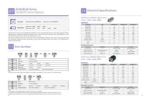
Series
BLM: BLM Series
2
Frame Size
57: 57mm (NEMA23)
3
Power
025: 25W
050: 50W
090: 90W
130: 130W
180: 180W
4
Encoder Resolution
1000: 1000-line(4000ppr)
4
Operating Environment
Parameters Insulation Level Insulation Resistence Ambient Temperature Storage Temperature
Descriptions B
DC 500V, above 10MΩ 0 to 40 °C
180W
The ACM series of AC servo motors and BLM series of brushless DC servo motors offer high performance with models ranging from 25W to 400W. Mounting is compatible with NEMA24 and NEMA23 motors on the market. Standard models come with a standard 2500-line or 1000line differential encoder with index signal (A, B, Z), and Hall sensors (U, V, W).
0.637 7.5 3000 4500 1.91 31.5
无刷直流电动机转矩脉动及其抑制方法综述
2 电流换向引起的转矩脉动
永磁无刷直流电动机工作时 , 定子绕组按一定 顺序换流, 由于各相绕组存在电感 , 阻碍电流的瞬 时变化 , 每经过一个磁状态 , 电枢绕组中的电流从 某一相切换到另一相时将引起电机转矩的脉动。抑 制由电流换相引起的转矩脉动的方法有 : 电流反馈 法、滞环电流法、重叠换相法、 PWM 斩波法等。 2 1 电流反馈法 非换相相电流的存在导致换相转矩脉动 , 很多 文献通过各种方法致力于使非换相相电流保持恒定 , 从而使转矩脉动为零。 一般来 说, 电流 反馈控制 可以分 为两种 形式 : 一种是直流侧电流反馈控制。其反馈信号由直流侧 取出, 主要控制电流幅值。由于它是根据流过直流 电源的电流信号进行的 , 因此只需要一个电流传感 器便可得到电流反馈信号。文献 [ 6 ] 对此方法进行 了分析。另一种是交流侧电流反馈控制。其反馈信 号由交流侧取出 , 此时 , 根据转子的位置来确定要 控制的相电流, 使其跟随给定。在换相过程中 , 当 非换相电流未到达给定值时 , PWM 控制不起作用 ; 当非换相 电流超过 设定值时 , PWM 控制开 始起作 用 , 关断所有开关器件 , 使电流值下降 , 直至低于 设计值再闭合被关断的开关器件, 使其值上升, 以 此往复 , 即可实现非换相相电流的调节 , 直至换相 完成。 84
董少波, 程小华
( 华南理工大学 电力学院 , 广州 510640) 摘 要 : 转矩 脉动是无 刷直流电动 机的固有 缺陷 , 它限 制了其在高 精度系 统中 的应 用。该文 详细 论述 了转矩 脉动 产生 的各种原 因 , 并给出 了相应的有 效的抑制 方法。 关键词 : 转矩脉动 ; 无刷直流电机 ; 抑制方法 中图分类号 : TM 36+ 1 文献标志码 : A 文章编号 : 1001 6848( 2010) 08 0083 04
永磁同步发电机的设计开题报告
开题报告填写要求1.开题报告(含“文献综述”)作为毕业设计(论文)答辩委员会对学生答辩资格审查的依据材料之一。
此报告应在指导教师指导下,由学生在毕业设计(论文)工作前期内完成,经指导教师签署意见及所在专业审查后生效。
2.开题报告内容必须用黑墨水笔工整书写或按此电子文档标准格式(可从教务处网页上下载)打印,禁止打印在其它纸上后剪贴,完成后应及时交给指导教师签署意见。
3.“文献综述”应按论文的格式成文,并直接书写(或打印)在本开题报告第一栏目内,学生写文献综述的参考文献应不少于10篇(不包括辞典、手册),其中至少应包括1篇外文资料;对于重要的参考文献应附原件复印件,作为附件装订在开题报告的最后。
4.统一用A4纸,并装订单独成册,随《毕业设计(论文)说明书》等资料装入文件袋中。
毕业设计(论文)开题报告毕业设计(论文)开题报告1)额定功率=7.5KW ; 2)额定电压3)额定转速; 4)额定效率;5)相数m=36); 7)额定功率因数(滞后);8)绕组形式: Y连接9)冷却方式:空气冷却;四、研究方法、步骤和措施永磁同步电机的电磁设计的设计研究一方面是针对永磁体,另一方面是针对电机的其它各相关参数。
设计当中所用到的方法主要是磁路等效法、类比法、有限元分析法。
具体步骤如下:1根据电机所要求的电机运行环境和设计具体要求选择永磁体的种类、合理尺寸和结构,并利用磁路等效法求的永磁体所能提供的磁势。
2 类比于同功率大小的电励磁同步发电机确定好电机的定子大小和主要尺寸比以及电机的定子绕组形式、线径大小和匝数。
3 计算出永磁电机的磁路、电路、电压调整率、短路以及其他电机相关参数。
4 采用磁场有限元分析法和磁场仿真软件对电机的磁场进行仿真以达优化设计的目的。
毕业设计(论文)开题报告。
无刷直流电机与永磁同步电机的比较研究_张勇
。对于 BLD-
CM 和 PMSM 的无位置传感器控制方法,基于反电动 势过 零 检 测 的 方 法 只 适 用 于 BLDCM, 不 适 用 于 PMSM。其余均适用于 PMSM 和 BLDCM 的无位置传 感器控制法有电感法、基于观测器法、 人工智能法、 磁链法等
[89 ]
2
结构比较
BLDCM 和 PMSM 的基本结构相似。以三相全桥
Comparison Study of Brushless DC Motors and Permanent Magnet Synchronous Motors
ZHANG Yong,CHENG Xiaohua ( School of Electric Power,South China University of Technology,Guangzhou 510460 ,China) Abstract: Brushless DC motor and permanent magnet synchronous motor has many similarities, but there are also some differences between them. The define methods of the brushless DC motor with permanent magnet synchronous motor was analyzed in the paper, the structures between them was compared, The operational performance indicators such as the speed range, starting performance, torque ripple, energy consumption and efficiency,the maximum transmission power capability of the motor, parameter sensitivity of brushless DC motor and permanent magnet synchronous motors were compared,and detailed theoretical explanation or proof was given. Based on the above comparison, the similarities and differences between the two was understood,meaningful guidance was given in the actual selection of the motor case. Key words: brushless DC motor; permanent magnet synchronous motor; structure; operating performance 造成知其然不知其所以然的局面。 为此, 本文立足 前人研究的科研成果,对 BLDCM 和 PMSM 做了一个 系统的理论比较,为同行的学习、 研究起指导作用, 为各生产企业选用电机提供一定参考价值 。
SM系列无刷电机说明书

SM Series Servo Motors Brushless servo motors featuring high performance slotless designThis design eliminates all detent torque in the motor, allowing the SM Series motors to provide extremely smooth motion, especially at low speeds. The slotless design also creates a higher rotor inertia, which is ideal for applications involving high inertial loads (such as lead screws and belt drives).Features• NEMA size 16 and 23• 0.8 to 11.3 lb-in continuous torque• Brushless construction • Slotless design providesnegligible detent torque, reduced torque ripple and high inertia • High-performance neodymium magnets• Thermostat protected • TENV housing • IP65 option• Feedback options – Encoder/Hall effect – Resolver• Connectorization choices • Special winding availability• Custom modifications available • Two-year warranty • CAD models available •CE CompliantContact Information:Parker Hannifin CorporationHydraulic Pump and Power Systems Div.14249 Industrial Pkwy. Marysville, OH 43040 USA Tel: (937) 644-3915 Fax: (937) 642-3738Web: /hpsSM Series Servo MotorsHigh-Performance Slotless DesignThe SM Series motors also feature a rugged anodized aluminum body and connector housing. An IP65 rating can be obtained on motors with PS or MS connectors and an optional shaft seal. All SM motors are CE (LVD) compliant.The SM Series brushless servo motors feature a slotless stator design.1@ 25°C ambient, 125°C winding temperature, motor connected to a 10” x 10” x 1/4” aluminum mounting plate. @ 40°C ambient derate phase currents and torques by 12%.2Operating at maximum bus voltage. Higher speed operation possible as custom.3Measured line-to-line, ±10%.4Value is measured rms of sine wave.5±30%, line-to-line, inductance bridge measurement @1Khz.6Initial winding temperature must be 60°C or less before peak current is applied.8A rms current in any phase for a sinusoidally commutated motor.9Total motor torque per A rms measured in any phase, ±10%.Note: These specifications are based on theoretical motor performance and are not specific to any amplifier.SM Series NEMA Size 16SM Series NEMA Size 16 NEMA Size 16 Performance Curves@ 40°C ambient derate phase currents and torques by 12%.2 Operating at max bus voltage. Higher speed operation possible as custom.3 Measured line-to-line, ±10%.4 Value is measured rms of sine wave.5 ±30%, line-to-line, inductance bridge measurement @1Khz.6 Initial winding temperature must be 60°C or less before peak current is applied.8 A rms current in any phase for a sinusoidally commutated motor.9 Total motor torque per A rms measured in any phase, ±10%.Note: These specifications are based on theoretical motor performance and are not specific to any amplifier.NEMA Size 23 Performance CurvesØ0.125 (3.18) Thru (4X)SM Series DimensionsNEMA Size 16 — Inches (mm)Ø0.218 (5.54) Thru (4X)NEMA Size 23 — Inches (mm)SM Series DimensionsSM Series - Recommended DrivesRecommended Parker Drives for SM Series Motor(AC powered)Recommended Parker Drives for SM Series Motor(DC powered)SM Series - Cable OptionsP-1A1P power cable is for use with P series drives and has extended ground wire to reach drive ground lug (heatsink).Brake leads included in either cable and not used when motor does not have a brake.Parker motors include brake rectifier preventing miswiring of the brake leads and either brake wire (red/blue) can be used as+ or -(with Parker drive-compatible terminations)Feedback Cables (with pin connector one end and flying leads)PS – Parker Standard (-xPSx) Pin ConnectionsPS Incremental Encoder/Hall (J and L) Pin ConnectionsPS Power & Brake Pin ConnectionsPowerThe PS connector option for the SM motors features high-quality Hypertac - Interconnectron circular connectors mounted to the motor body.Mating cables are specified and ordered separately. The PS option joins the motor phase wires and brake leadsIP65.NOTE: For customers preferring to build their own mating cables, a PS connector kit (Part #: PS-CONN-KIT), is available. The kit contains a mating PS power connector, PS feedback connector and connector pins, allowing customers to build cables to their own specification. Special tools are not included in the kit.NOTE: Brake will operate regardless of polarity of connectionLC – Low Cost (-xLCx) Pin ConnectionsLC Incremental Encoder/Hall (R) PinLC Resolver (R) Pin ConnectionsThe LC connector option for the SM motors features a high-quality and low cost molded connector. This option uses the very common Amp, or Tyco brand of connectors on the ends of 8” motor and feedback cables. These connectors are usually available from most electrical supply houses.Feedback2Power PowerBrakeThe LC connector option is available on all SM size 16 and 23 stack length motors. The feedback type selections that are available with the LC option are J (incremental encoder) and R (resolver) feedback options.The LC connections support the brake option for SM motors. When the brake option is ordered, the motor ships with three individual connectors: One for feedback, one for power and the last for the brake. Without a brake, the motor only comes with the feedback and power connectors.Feedback Connector Tyco 172171-1Mating Connector Tyco 172163-1Mating Pin (F) Connector Tyco 170362-1Tyco 172167-1Tyco 172159-1Tyco 170362-1 Tyco 170362-1Wiring Connections for:FL – Flying Leads with Enclosed Feedback (-xFLx) FO – Flying Leads with Exposed Feedback (-xFOx)FL and FO Cable MotorPower, Motor Feedback andFO/FL Flying LeadsThe FO/FL cable option for the SM motors features flying leads for both feedback and power connections. The only variable is whether or not the feedback device is fully enclosed (FL) or fully exposed (FO).These options are for OEM customers that wish to reduce cost as much as possible and fully integrate their own cable solutions.10 - 10’ hard wired cableThe “10” cable option for the SMhard wired into the rear of the motor. The cables have full strain relief and completely enclosed feedback. While custom lengths are available, it is not recommended to exceed 10 feet between motor and drive.NOTE: Brake will operate regardless of polarity of connection10’ Cable Motor Power, Motor Feedback and Brake (J) Wiring ConnectionsMS – Military Style (-xMSx) Pin ConnectionsMS Incremental Encoder/Hall and Brake (E and L) Pin ConnectionsMS Power Pin ConnectionsAmphenol CONN PT06E-14-12P(023) Feedback connector part number:Amphenol CONN PT02E-14-18S(023)MS Resolver and Brake (R) Pin ConnectionsPowerFeedbackThe “MS” connection option for the SM Series motors provides quick disconnect, bayonet style connectors attached to the motor body. Mating cables are specified and ordered separately.With the “MS” connection option, the motor phase wires are in one connector, and the hall, encoder, temperature switch, and brake wires are in the other connector. This option works well when using an amplifier with a built-in controller, or when all cables enter into a cabinet or enclosure and then are wired into a terminal strip.When specifying the “R” (resolver) feedback option, the motor phase wires reside in one connector, the resolver signal, temperature switch, and brake wires in the other.The “GS” connection option for the SM Series motors provides quickdisconnect, bayonet style connectors attached to the motor body. Mating cables are specified and ordered separately. Wiring for the “GS”connection option for SM motors is similar to the “MS” option, except thetemperature switch leads have been moved to the feedback connector. This connection option should be selected when operating the SM motors with the Gemini family of amplifiers.GS – Gemini Amp Series Connection (-xGSx)GS Motor Wiring ConnectionsGS Encoder/Hall Feedback Wiring ConnectionsPowerFeedbackFeedback OptionsResolver SpecificationsHall-Effect SpecificationsEncoder SpecificationsR2R1S3S1S1-S3 R1-R2E S2-S4 = KE R1-R2 SINØPhase B-APhase A-CClockwise rotation as viewed from front shaft.Phase C-BHall #1Hall #2Hall #3Resolver SchematicCommutation ChartSM Series OptionsFill in an order code from each of the numbered fields to create a complete model order code.SeriesSMBrushless Servo MotorsFrame (Magnet Length)161Size 16 frame, 1 stack magnet 162Size 16 frame, 2 stack magnet 231Size 23 frame, 1 stack magnet 232Size 23 frame, 2 stack magnet 233Size 23 frame, 3 stack magnetWindingA 16 or 23B16 or 23FeedbackE 1000 ppr encoder*L 5000 line encoder*RResolver***Includes Hall-effect**Not available on any size 16 FrameShaft OptionsN Normal F FlatKKeyway**Not available on size 16 motorsConnectionPS Parker standard connectors, all feedback optionsLCLow cost connectors 1010 ft. (3m) cable*FL Flying leads (housed feedback)FO Flying leads (exposed feedback)MS Military styleGSGemini amp series ***Cable is hard-wired**See amplifier sections for specific motor/amplifier compatibilityOptionsN NoneB 24 V failsafe spring brake*BV 24V failsafe spring Brake with IP 65 shaft seal VIP 65 shaft seal***Available on 23 frame with any connector option except FO, not available on 16 frame.**Available with PS, LC, MS or GS connectors only, not available on size 16 frame.SM Series Ordering InformationParker Hannifin CorporationElectromechanical Product Sales OfficesAustraliaParker Hannifin (Australia) Pty Ltd.9 Carrington Road Castle Hill NSW 2154AustraliaTel: +61 (0) 2 9634-7777 Fax: +61 (0) 2 9634 3749BrazilParker Hannifin Ind. Com Ltda.Av. Lucas Nogueira Garcez 2181Esperança12325-900 Jacareí, SP Tel: 12 3954 5100Fax: 12 3954 5262Email: a ***************************CanadaParker Hannifin (Canada) Inc.160 Chisholm DrMilton, Ontario L9T 3G9 Tel: 905-693-3000 Fax: 905-876-1958Email:****************************ChinaParker Hannifin Motion & Control (Shanghai) Co., Ltd280 Yunqiao Rd. Jin Qiao Export Processing ZoneShanghai 201206, China Tel: (86-21) 50312525Fax: (86-21) 64459717FranceParker SSD Parvex 8 avenue du Lac B.P . 249F-21007 Dijon CedexTel: +33 (0) 3 80 42 41 40Fax: +33 (0) 3 80 42 41 23GermanyElectromechanical EuropeParker Hannifin GmbH & Co KG Robert-Bosch-Strasse 22 D-77656 Offenburg GermanyTel: +49 (0) 781 509 0Fax: +49 (0) 781 509 98176Email:********************IndiaParker Hannifin India Pvt. LtdAutomation Group-SSD Drives Div.133 & 151 Developed Plots Estate Perungudi, Chennai 600 096Tel: 044-4391-0799ax: 044-4391-0700ItalyParker Hannifin SpA Via Gounod 120092 Cinsello Balsamo Milano, ItalyTel: +39 02 361081Fax: +39 02 36108400Email: ********************KoreaParker Hannifin Korea9th Floor KAMCO Yangjae Tower 949-3 Dogok 1-dong Gangnam-gu Seoul 135-860, Korea Tel: 82-2-559-0454Fax: 82-2-556-8187MexicoParker Hannifin de Mexico Eje uno Norte No.100Parque Industrial Toluca 2000 Toluca, CP 50100 México Tel: 52-722-275-4200Fax: 52-722-279-0316SingaporeParker Hannifin Singapore Pte Ltd 11, Fourth Chin Bee Road Singapore 619702Tel: (65) 6887 6300Fax: (65) 6265 5125/6261 4929TaiwanParker Hannifin Taiwan Co., Ltd No. 40, Wuchiuan 3rd Road Wuku Industrial ParkTaipei County, Taiwan 248ROCTel: 886 2 2298 8987Fax: 886 2 2298 8982ThailandParker Hannifin (Thailand) Co., Ltd.1265 Rama 9 RoadSuanluang, Bangkok 10250 ThailandTel: (66) 2 186 7000Fax: (66) 2 374 1645UKParker Hannifin Ltd.Tachbrook Park Drive Tachbrook Park Warwick CV34 6TUTel: +44 (0) 1926 317970Fax: +44 (0) 1926 317980USAParker Hannifin Electronic Motion and Controls Division 1140 Sandy Hill Road Irwin, PA 15642Tel: 800-358-9070Email:**********************Parker Hannifin Hydraulic Pump & Power Systems Division 2101 N. Broadway New Ulm, MN 56073Tel: 800-358-9070Email:**********************Issue Date 6/2021© 2021 Parker Hannifin Corporation BRO-SM-0612SM Series: Made in the USA。
IPM介绍 Motors
®Brushless Interior Permanent Magnet (IPM) Motors –A New Solution for High Performance AppliancesPermanent magnet (PM) brushless (BL) motors have emerged in recent years as a very strong contender to replace induction motors used in electronically controlled variable speed applications. In most cases, BLPM motors can provide superior performance in terms of increased efficiency and reduced noise, while the total cost differential for motor plus electronics is subject to relatively fast payback, especially considering the increasing cost of energy.At the core of a BLPM motor are the PMs, which are placed in the rotor and provide the magnetizing flux. One immediate advantage is that in a typical design, there are virtually no rotor losses. Different magnet grades can be employed for rotor manufacturing, with ceramic-ferrites and rare-earth, especially neodymium-iron-boron (NdFeB), being the common choices. In particular, the sintered NdFeB isa strong material with energy density higher by one order of magnitude than that of the lower cost ferrites. Although NdFeB is a more expensive material, it enables overall motor size reduction and/or energy increase and, through careful design, can lead to an attractive motor solution.Fig. 2 Electromagnetic torque components in an example IPM motor. Drive electronics tracks rotor position and controls the vector current inorder to maximize torque production.Fig. 1 Schematic cross-section of a 4-pole brushless (BL) motor with surface mounted permanent magnets (PM; left) and of an interior PM motor (right). Magnets of North and South polarity are shown in red and blue.BLPM motors can be classified in two major groups: motors with the PMs mounted on the surface of the rotor and motors with PMs placed in the interior of the rotor core (Fig.1). The first group is commonly referred to as surface PM (SPM), and the typical manufacturing technology involves gluing arc magnets and/or securing them with special tape on the outer surface of a rotor core. While this technology may be cost effective in conjunction with large ferrite magnets or with bonded magnet rings, it presents challenges for the sintered NdFeB designs. In this case, the solution is more complicated because, in order to cope with thin magnets and to minimize eddy-current losses in the magnets, multiple smaller magnets are often used to make one pole.magnetic field of the air-gap, in an IPM the PMs are shielded by the rotor steel that provides a leakage path for the arma-ture reaction flux. As a consequence, thinner magnets can be employed, potentially resulting in material cost savings.The synchronous electromagnetic torque in an IPM motor has two major components (Fig. 2). The main component is the alignment torque, which is proportional with the flux linkage in the stator windings produced by the rotor magnets and with the vector component of the stator current that is in quadra-ture with the magnet flux. This current component is “active” only, i.e. only produces torque and does not contribute to the magnetization of the motor magnetic circuit. In an SPM, this is the only synchronous component of the electromagnetic torque.In an IPM, due to the rotor variable magnetic reluctance, i.e. saliency, an additional torque component is developed. By means of electronic control, the torque angle, i.e. the angle between the magnet flux phasor and the current phasor, can be optimally set in order to increase the torque output for a given current magnitude. In the example of Fig. 2 the optimal angle is approximately 115 degrees.On the other hand, IPM motors typically employ less expensive rectangular blocks, which are placed inside slots made in the laminated rotor core. Magnet retention is therefore enhanced and yields to simplifications in the manufacturing process. There are a large variety of designs for IPM rotors; shown in Fig.1 is just the most conventional version with PM blocks magnetized parallel to the center pole radius.Another major type of IPM rotor (not shown) employs magnets placed in a “spoke” arrangement along the rotor radius and magnetized tangentially. The “spoke” design has the intrinsic advantage of magnetic flux concentration, so that in high polarity motors the flux density in the motor air-gap is increased. This leads the way to further performance improvement and/or size reduction. Many combinations of the magnet shape, position and number of magnets per pole is possible for IPM motors. In recent years, A. O. Smith Corporation has developed proprietary solutions to optimize designs for different applications.Better demagnetization withstand is another advantage of IPM motors. Unlike in the SPM, in which the PM is directly exposed to theThis maximum torque per amp control procedure requires a demagnetizing current component that also reduces the mag-netic circuit loading and core losses. As shown in the graph, an IPM motor has the potential of increased specific power or reduced size for the same rated power, as compared with an SPM machine. At reduced loads, both the active (quadra-ture) and demagnetizing current component are reduced yielding a relatively flat efficiency curve, yet another advantage of BLPM machines over induction motors.especially at low speed or torque. A concentrated winding design can be more sensitive than its distributed winding counterpart in terms of the influence of tolerances, particularly those of the air-gap, on the motor unbalanced magnetic pull.The example in Fig. 4 is from an electromagnetic finite-element model analyzed with the PC-FEA software produced by the SPEED Laboratory, University of Glasgow, UK. This detailed method of motor performance simulation is preferred because of the strong non-linearity present in the magnetic circuit of a high-performance IPM design.Despite recent advancements, for some applications the added cost of a variable speed drive still remains prohibi-tive. In this case, the induction motor, the industry “work horse” for the last century, appears to be irreplaceable. However, BLPM machines can also be made to operate directly from the mains and benefit of increased efficiency without electronics!The solution, called a line-fed IPM motor involves the use of a rotor that includes, apart from the PMs, also a squirrel cage, similar to that of an induction machine. In the cut-away rotor example of Fig. 3, three magnets per pole are fitted in the rectangular slots. During the motor transient start-up, the rotor cage contributes to the production of an asynchronous torque that overcomes a PM transient braking torque and accelerates the rotor. In typical steady-state operation, the rotor moves insynchronism with the air-gap revolving magnetic field.Fig. 3 Stator and cut-away rotor for a 2-pole line-fed IPM motor, which operates at synchronous speed without electronic controls.The rotor includes a squirrel cage and PMs.Fig 4. Magnetic field in the cross-section of a 3-phase 9-slot 6-pole electronically controlled IPM motor. Coils are wound around every tooth and inter-connected to produce a concentrated type winding.From the point of view of electronic commutation, brushless PM motors can be driven with “trapezoidal” or “sinusoidal” current waveforms. The control of the first type, also referred to as BLDC, is typically simpler, especially when done sensor-less, i.e. without a rotor position sensor. Nevertheless, the BLAC control with sinewave currents typically has superior performance both in terms of increased efficiency and reduced noise.IPM motors particularly shine when used in conjunction with vector control. In this case, the electronic controller “tracks” the rotor position with respect to the stator (armature) field and “injects” the current such as to optimize torque production and efficiency, as explained with reference to Fig. 2. The salient rotor structure of the IPMs lends itself to robust sensorless applications.In principle, both SPM and IPM rotor types can be mated with the same stator design. However, the design should be care-fully completed in order to ensure that, among other char-acteristics, a sinusoidal back EMF is achieved so that the elec-tromagnetic torque ripple is reduced. In this respect, a low harmonic content of the air-gap magnetic field is preferable and is also beneficial for reducing core losses.A distributed stator winding – e.g. concentric or lap, typical for induction machines – can also be used with a lamination having more than one slot per pole and phase (e.g. Figs. 1 and 3). For fractional slot designs, a concentrated winding with coils wound around a tooth can be employed. This second choice may result, depending on the actual application require-ments, in reduced copper losses that could boost efficiency,Electronic control boosts motor and drive performanceA. O. Smith Corporate Technology Center 12100 West Park Place P . O. Box 245012Milwaukee, WI 53224414-359-4200© 2008 A. O. Smith Corporation All Rights Reserved100% recycled materialsDr. Dan M. Ionel is the Electromagnetics Engineering Fellow of A. O. Smith Corp., Milwaukee, WI. He has 20+ years of experience with electric motors and earlier in his career worked in the U.K. for Invensys Brook Crompton Co. and for the SPEED Laboratory, University of Glasgow.ApplicationsSome of the most popular IPM applications, possibly not familiar enough to the wide general audience, are the electric motors/generators of hybrid or all-electric vehicles. In the servo motor world more and more designs are shifting away from SPM to IPM to take advantage of the inherent advantages previously discussed. In principle, there are no size limitations to IPM designs and these can be developed from small fractional horsepower (hp) to large – hundreds of hp ratings.Compressors, including those of smaller ratings for residential unitary air-conditioning applications, are potential candidate applications for IPM designs. For example, the use of a line-fed IPM, as the one exemplified in Fig. 3, can increase the motor rated efficiency by up to 4 points above the already high efficiency of a top of the line induction motor. Such improvement is possible while maintaining the starting torque requirements of a demanding application, such as a reciprocating compressor. The addition of electronics makes possible true variable speed operation and enables further energy savings achievedbyFig.5 AOS ECM (Electronically Commutated Motor) - motor and electronics platform.running the driven mechanism for longer time but at substantially reduced speed and torque. For relatively small ratings, the power electronics hardware for IPMs is based on the AOS ECM platform, which is currently in production (Fig. 5), and a new controller incorporates proprietary vector algorithms that maximize motor performance.®。
BLDCM两相短路的四步换相容错运行方法
1414
电工技术学报
2019 年 4 月
strategy is simulated and tested, the experimental results show that the peak value of non-fault-phase current during fault-tolerant operation of motor is about 1.5 times of that during normal operation of motor, the peak value of the fault-phase current during fault-tolerant operation of motor is about 1.25 times of that during normal operation, the torque fluctuation increase 20% and the fluctuation of rotational speed is less than 5%.
关键词:无刷直流电机 两相短路 故障定位 四步换相 容错运行 中图分类号:TM351
A Four-Step Commutation Fault-Tolerant Operation Method for Two-Phase Short-Circuit of BLDCM
Zhou Qixun1,2 Wang Kun1 Liu Na1 Zhang Yufeng1 (1. College of Electrical and Control Engineering Xi’an University of Science and Technology
电机齿槽力介绍
Published on Machine Design ()Reducing cogging torque in brushless motorsbyCreated 06/01/2000 - 03:00Brushless dc motor windings are similar to the windings in a multiple-phase ac motor. But brushless motors also contain a permanent --magnet rotor and a sensor to detect the rotor position to produce signals that control electronic switches for commutation. The most common position sensor is a Hall-effect device.The shape of the magnetic flux density in the air gap of an assembled motor is an indicator of its cogging torque. An example are these three curves shown for one pole pair. Each theoretical curve represents different magnetization and pole-arc angles for the same air gap length, magnet thickness, and material.A typical nine-slot, eight-pole motor produces this cogging curve during one of 18 identical cycles in a single revolution (360 electrical degrees). Because it has four pole pairs, one mechanical revolution contains 72 cycles. Superimposing this curve on the shaft torque curve for one electrical revolution provides total motor ripple at a selected current level. For certain applications, current injected into the windings can cancel some harmonics to reduce cogging torque, and occasionally, it can become smaller than the bearing torque.A 12-slot, 8-pole motor generates three magnetic-flux distribution curves when using different magnetic materials, altering the thickness of the magnet, and adjusting the air gap so the peak flux density remains constant.Cogging torques are plotted from the three waveforms in Flux distribution: 12-slot, eight-pole motor. Small changes in the magnetic waveform can generate significant variations in cogging torque for each of the three waveforms, although all magnets produce nearly identical motor parameters and performance, otherwise. In some cases, the slot fill may be too high to handle larger diameter wires during attempts to minimize cogging, but usually, a combination of wire size and turns can be found without making the motor impossible to wind.The largest cogging torque waveform amplitude is the 12 slot in a family of curves for 6, 9, 12, and 15-slot lamination motors. The curves indicate that for an eight-pole motor with a 9-slot lamination produces the least cogging torque. In practice, the 12-slot lamination may be used when the means for developing a new lamination may not be readily available. When the application is sensitive to cogging torque, then skewing the magnets or the stator is an option but may result in a combination of more copper, iron, and magnetic material.The table Characterizing multiple-pole motors shows that motors may be built with 4, 6, 8, or 12 rotor poles for an 18-slot lamination, but these test results show that the motor with a 12-pole rotor produces the highest amount of cogging torque for the same inner diameter and slot opening.Comparing the effects of even versus odd slots, cogging is highest for the 6-pole rotor among 4, 6, 8, and 12-pole configurations in a 15-slot lamination. The slot opening and inner radius of the stator are again a constant and the same changes are made to the rotor as described for the 18-slot lamination. The amplitudes for the 15-slot compared to the 18-slot are significantly different as are the air gap diameters, magnet material, motor geometry, and stack lengths.Cogging and torque are measured on a six-slot, eight-pole motor with a ring magnet. Calculated data are plotted as the smooth curve and the measured data are plotted with circular markers. The data were obtained by running the motor with a servodrive at a constant speed of 0.5 rpm while the torque transducer provides an output voltage proportional to the cogging torque. In this case, the calculated values are conservative.Another configuration changes the slot opening for a given design and compares the cogging torque waveforms. This is shown for a 12-slot, eight-pole motor. The curve with the largest amplitude has a 4-mm slot opening and the three other curves represent 3, 2, 1-mm slot openings with decreasing amplitude. As the slot opening becomes smaller, the cogging torque also becomes smaller but at a faster rate. That is, the reduction is much greater going from a 2 to 1-mm slot than going from a 4 to 3-mm slot. For fractional-horsepower motors, the slot opening is usually not smaller than 1.5 mm. In any case, there will always be some cogging, but it is up to the designer to decrease this as much as possible using these techniques.Cogging torque in dc brushless motors comes from variations in magnetic field density around a rotor's permanent magnets as they pass the nonuniform geometry of the slot openings in the stator. In applications such as servosystems and spindle drives, the pulsating speed that cogging generates can blemish machined surfaces or reduce position accuracy.Unfortunately, classical electromagnetic calculations do not provide the data needed to determine how much cogging torque might develop in a new paper design. Although a complete finite-element analysis may be an alternative to manual methods, it usually requires more project time than is available. In most cases, several prototypes must be made to measure and eventually reduce the cogging torque. Thus, it is critical to have a simple check list of major factors that determine cogging torque during the initial design procedure so several iterations can be made before finalizing the drawings.Major factors affecting cogging torque include magnetic wave shapes, air-gap length, slot opening, number of stator slots and rotor poles, skewing, copper fill, pole pitch, flux distribution or density, magnet volume, and material weight. Relationships between some of these factors, including electrical degrees/cycle, and cycles/rev for the most widely used motor configurations are conveniently shown in the table Characterizing multiple-pole motors.Analyzing the ripple torque for each type leads to a set of guidelines for new designs. For example, the table shows that the maximum number of cycles in one electrical cycle for a stator with an even number of slots can equal the number of slots itself. But for a motor with an odd number of slots, the number of cycles can be twice the number of slots.Moreover, for a given frame size and type of lamination, slot and pole combinations as well as different pole arc to pitch ratios and magnetization, can produce different cogging torques. Keeping the number of poles on both rotor and stator ID and slot openings constant, and varying the number of slots, shows how cogging torque behaves for different slot and pole combinations.The accompanying diagrams show how to combine these factors to arrive at a design that generates minimum cogging. In any case, skewing the magnets or the stator core often can lower cogging a bit more. When a design without skewing already shows minimal cogging, the skew angle required to reduce cogging below a particular value will be much smaller. Also, designing for a trapezoidal or nearly sinusoidal air-gap waveform (made by varying the pole arc to pole-pitch ratio) is a common practice that often reduces cogging torque even further.Portions of this article were contributed by Kartik Sitapati and Rob St. Germain, Kollmorgen Corp., Radford, VA 24141, (540) 633-4124, Fax: (540) 731-0847, [1]Source URL: /article/reducing-cogging-torque-in-brushless-motors-0601Links:[1] 。
松下VF-7E原版说明书
VF-7E/VF-7F/VF-8X/VF-8Z AC INVERTERSVF SeriesAC INVERTER LINE-UP2•Sensorless vector control •Very low acoustic noise •Multiple protection features•Type approved under EC, LVD and EMC standards (EN Type)R9551112 (200V)R9551113 (400V)E1149170.2kW 2.2kW 0.2kW 3.7kW0.75kW 3.7kW0.2kW 3.7kW 0.75kW 3.7kWIP20Single-phase 200V Three-phase 200V Three-phase 400V•Type approved under UL and CUL standards (UL Type)Three-phase 200V Three-phase 400VVF-8XVF-8Z• Unique PWM control (V/F control)• Very low acoustic noise • Extensive operating range3Standard line-up with the TÜV/UL/CUL-approved invertersEUROPENORTH AMERICAVF series inverters with enhanced,sophisticated functioning meet the world’s toughest approvals,and fulfill the global market’s demanding needs.UL/CUL approval······ Obtained both approvals for assured safetylevels.Approved product rangeSafetyI Product conforming to the EC Low VoltageDirective (TÜV-approved product)• Conforms to DIN VDE 0160I Product conforming to the UL standardI Accident prevention system• Data lock function controlled by password.I Also conforms to the EMC Directive• By combination use with EMI filter.I Programmable password for operationalintegrityI Electronic thermal overloadOperabilityI Improved monitoring functions• Simple operation for frequency settings.• The main display on the control panel can be alteredbetween command frequency, output frequency and othersettings.• The four most recent faults are stored in the memory after apower failure to facilitate system diagnosis.FunctionsI Simple vector control• Simple vector control ensures a high torque even at lowspeeds (150% torque at 1 Hz).• The output torque characteristics for general-purpose motorswhen operated by an inverter at variable speeds are shownbelow.I Auto tuning function (with slip compensation)• This function automatically detects and controls the constantof a motor required for vector control and is applicable tothree-phase squirrel-cage motors with 2, 4 or 6 poles.I Speed search function• The inverter is activated without stopping the motor (on afree run) for a changeover from the commercial run to aninverter run or a return from sudden power failure.200V 0.4kW200V 1.5kW45MODE DISPLAY (RUN/FAULT)6ParameterNo.201234Control terminalNo.16SW3Reset inputReset lockoutJog functionReset inputReset lockoutJog functionControlterminalNo.14SW1Multi-speedfunctionAnaloginputchangeoverControlterminalNo.15SW2AuxiliarystopinputNote:Data can be read only when the power is on.❋The same value as inverter's rating.• Notes on setting parameters1.parameter settings can be modified.2. No values can be modified unless the Lock indicator is off.3. While the inverter is stopped, it cannot be operated unless the Lock indicatoris ON.4. If the function setting returns to the "Operation Prep. Complete" state duringdata modification while an external start signal is received, the error code"OP" will be displayed, and the inverter will remain inoperative.5. The values set by pressing the Set button are stored in the memory even if thepower is off.ParameterNo.205678910Terminal Function Selection by Parameter No.20ControlterminalNo.14SW1Multi-speedfunctionControlterminalNo.15SW2Multi-speedfunctionControl terminalNo.16SW3Multi-speedfunctionReset inputResetlockoutJog functionAuxiliary stopoutputFUNCTION SETTING PROCEDUREMode displayMain displaymode display flashes.completed78SafetyI Product conforming to the EC LowVoltage Directive (TÜV-approved product)• Conforms to DIN VDE O160I Product conforming to the UL standard I Accident prevention system• Data lock function controlled by password I Also conforms to the EMC Directive • By combination use with EMI filterI Programmable password foroperational integrityI Electronic thermal overloadOperability• Easy to operate by means of Digital Parameter Programming on operation panel.• Enhanced monitoring features and space saving design.• Super compact design with very powerful and extensive parameters.Functions• Matsushita’s unique PWM control for good low speed torque and control.• Programmable 15.0kHz carrier frequency, low acoustic noise.I Frequency Skip Feature:Vibrations resulting from resonance with associated facilitiesare prevented by skipping resonant frequencies. Up to three frequencies can be skipped, and skip frequency span is user adjustable.I Max.Output Voltage Setting:The inverter output voltage can be adjusted by AVR (Automatic Voltage Regulator).I Jog Operation:Select either local or external jog operation, for which acceleration/deceleration time can be independently specified.I Smooth Operation at Low Frequencies:Our unique PWM control method ensures smooth operation in the low frequency range with minimum torque ripple.I Overload Function Protection:Complete motor overload protection over a wide range of operating conditions by selection of device functions according to motor characteristics.I Ride-Through Restart Capability:Restarts after power failures or surges can be programmed in different modes depending on load or system conditions. A wait time programming feature is also included.Device FeaturesSystem FeaturesI Operation Status Feedback:Provides run, arrival, frequency detection and fault alarm signals. The user can create commands for the next process step using those signals.I Acceleration/Deceleration linked withMultispeed Operation:In addition to multispeed (eight speeds) and multi-acceleration/deceleration rates (four rates), this device enables combination of those rates (four speeds) with link capability. Flexible speed/acceleration/deceleration combinations allow easy system design.I Wide Choice of Speed Control:Motor speed can be controlled with external analog signal,manual control or in two to eight steps with external switching signal.I DC Brake Range and Time Adjustment:T o ensure reliable stopping during deceleration, DC braking can be activated when output frequency is reduced below the specified stop frequency (0.5 to 60 Hz). The DC brake application time can be adjusted from 0 to 120 seconds.200V 2.2kW200V 0.75kW9*1<Precautions>When using the carrier frequency at 12.5kHz or15kHz, the output current must be decreased to the following values. (The current does not need to be decreased for capacities other than those listed below.)3-phase 200V input series 0.75kW12.5kHz : (rated output current) x 0.95 (3.4A) 15kHz : (rated output current) x 0.9 (3.2A) 3-phase 200V input series 3.7kW12.5kHz : (rated output current) x 0.94 (14.5A) 15kHz : (rated output current) x 0.87 (13.5A) 3-phase 400V input series 3.7kW12.5kHz : (rated output current) x 0.81 (7.0A) 15kHz : (rated output current) x 0.62 (5.4A)MODE DISPLAY(RUN/FAULT)10Note: Data can be read only when the power is on.❋ The same current value as the rated current of the inverter.FUNCTION SETTING PROCEDUREto get the parameter setting mode.• Notes on setting parameters1. While the inverter is in operation, only values for the numbers in the of parameter settings can be modified.11I Accident prevention system• Data lock function controlled by passwordI Programmable password foroperational integrity12SafetyOperability• Easy to operate by means of Digital Parameter Programming on operation panel.• Enhanced monitoring features and space saving design.• Super compact design with very powerful and extensive parameters.Functions• Matsushita’s unique PWM control for good low speed torque and control.• Programmable 15.0kHz carrier frequency, low acoustic noise.I Frequency Skip Feature:Vibrations resulting from resonance with associated facilitiesare prevented by skipping resonant frequencies. Up to three frequencies can be skipped, and skip frequency span is user adjustable.I Max.Output Voltage Setting:The inverter output voltage can be adjusted by AVR (Automatic Voltage Regulator).I Jog Operation:Select either local or external jog operation, for which acceleration/deceleration time can be independently specified.I Smooth Operation at Low Frequencies:Our unique PWM control method ensures smooth operation in the low frequency range with minimum torque ripple.I Overload Function Protection:Complete motor overload protection over a wide range of operating conditions by selection of device functions according to motor characteristics.I Ride-Through Restart Capability:Restarts after power failures or surges can be programmed in different modes depending on load or system conditions. A wait time programming feature is also included.Device FeaturesSystem FeaturesI Operation Status Feedback:Provides run, arrival, frequency detection and fault alarm signals. The user can create commands for the next process step using those signals.I Acceleration/Deceleration linked withMultispeed Operation:In addition to multispeed (eight speeds) and multi-acceleration/deceleration rates (four rates), this device enables combination of those rates (four speeds) with link capability. Flexible speed/acceleration/deceleration combinations allow easy system design.I Wide Choice of Speed Control:Motor speed can be controlled with external analog signal,manual control or in two to eight steps with external switching signal.I DC Brake Range and Time Adjustment:T o ensure reliable stopping during deceleration, DC braking can be activated when output frequency is reduced below the specified stop frequency (0.5 to 60 Hz). The DC brake application time can be adjusted from 0 to 30 seconds.VF-8XVF-8ZVF-8X : EN type(all)UL type(200V 5.5kW , 400V 5.5kW .7.5kW) VF-8Z : all13*1 Note) The rated output current is for a carrie frequency of 10kHz or less.when using at 12.5kHz or 15kHz, decrease the rated current to the following values and use. 12.5kHz : (rated current) x 0.9 15.0kHz : (rated current) x 0.8*2 Note) The rated output current is for a carrie frequency of 10kHz or less.when using at 12.5kHz or 15kHz, decrease the rated current to the following values and use. 1) 5.5~22kW12.5kHz : (rated current) x 0.9 15.0kHz : (rated current) x 0.8 2) 30, 37kW12.5kHz : (rated current) x 0.7 15.0kHz : (rated current) x 0.6MODE DISPLAY(RUN/FAULT)14ParameterNo.201234Control terminalNo.16SW3Reset inputReset lockoutJog functionReset inputReset lockoutJog functionControlterminalNo.14SW1Multi-speedfunctionAnaloginputchangeoverControlterminalNo.15SW2AuxiliarystopinputNote:Data can be read only when the power is on.❋The same value as inverter's rating.❋❋5.5~15kW: 005.0,19~37kW: 015.0• Notes on setting parameters1.parameter settings can be modified.2. No values can be modified unless the Lock indicator is off.3. While the inverter is stopped, it cannot be operated unless the Lock indicatoris ON.4. If the function setting returns to the "Operation Prep. Complete" state duringdata modification while an external start signal is received, the error code"OP" will be displayed, and the inverter will remain inoperative.5. The values set by pressing the Set button are stored in the memory even if thepower is off.ParameterNo.205678910Terminal Function Selection by Parameter No.20ControlterminalNo.14SW1Multi-speedfunctionControlterminalNo.15SW2Multi-speedfunctionControl terminalNo.16SW3Multi-speedfunctionReset inputResetlockoutJog functionAuxiliary stopoutputFUNCTION SETTING PROCEDUREMode displayMain displaymode display flashes.completed15The models which are more than 1.5kW are with fans.VF-7EVF-7FVF-8XVF-8ZDIMENSIONS <Figure No. Table>Three-phase 200V Single-phase 200V Three-phase 400VUL Type EN Type EN Type UL/EN Type UL Type EN Type UL/EN Type UL Type UL Type EN Type-0.2kW Fig.1Fig.2Fig.2-0.4kW Fig.1Fig.2Fig.2-0.75kW Fig.2Fig.2Fig.2Fig.4 1.5kW Fig.3Fig.3Fig.4Fig.4 2.2kW Fig.4Fig.4Fig.4Fig.4 3.7kW Fig.4Fig.4-Fig.4Three-phase 200V Single-phase 200V Three-phase 400VThree-phase 200V Three-phase 400VThree-phase 400V0.2kW Fig.2Fig.2-0.4kW Fig.2Fig.2-0.75kW Fig.2Fig.2Fig.4 1.5kW Fig.3Fig.4Fig.4 2.2kW Fig.4Fig.4Fig.4 3.7kW Fig.4-Fig.45.5kW Fig.A Fig.A Fig.A 7.5kW Fig.B Fig.A Fig.D-111kW Fig.B Fig.D-2Fig.D-215kW Fig.D-2Fig.D-2Fig.D-219/22kW Fig.D-3Fig.D-3Fig.D-330/37kW Fig.D-4Fig.D-4Fig.D-45.5kW Fig.A7.5kW Fig.A11kW Fig.C15kW Fig.C19/22kW Fig.D-230/37kW Fig.EUnit: mm16The built-in electronic thermal VF-8X 11-37kW / VF-8Z 15-37kW17WIRING DIAGRAMVF-7EVF-8XVF-7FThe built-in electronic thermal 05V/010V Note:When setting the frequency with the 4 to 20mA signal,short circuit terminal Nos.2 and 10• Control Circuit WiringVF-8Z1819Please contact ........。
- 1、下载文档前请自行甄别文档内容的完整性,平台不提供额外的编辑、内容补充、找答案等附加服务。
- 2、"仅部分预览"的文档,不可在线预览部分如存在完整性等问题,可反馈申请退款(可完整预览的文档不适用该条件!)。
- 3、如文档侵犯您的权益,请联系客服反馈,我们会尽快为您处理(人工客服工作时间:9:00-18:30)。
IEEE TRANSACTIONS ON INDUSTRY APPLICATIONS, VOL. 41, NO. 2, MARCH/APRIL 2005599Direct Torque Control of Brushless DC Drives With Reduced Torque RippleYong Liu, Student Member, IEEE, Z. Q. Zhu, Senior Member, IEEE, and David HoweAbstract—The application of direct torque control (DTC) to brushless ac drives has been investigated extensively. This paper describes its application to brushless dc drives, and highlights the essential differences in its implementation, as regards torque estimation and the representation of the inverter voltage space vectors. Simulated and experimental results are presented, and it is shown that, compared with conventional current control, DTC results in reduced torque ripple and a faster dynamic response. Index Terms—Brushless dc (BLDC) drives, direct torque control (DTC), permanent-magnet motor.I. INTRODUCTIONTHE permanent magnet brushless ac (BLAC) and brushless dc (BLDC) drives [1], [2] are used extensively for many applications, ranging from servos to traction drives. They differ primarily in their current and back-electromotive-force (EMF) waveforms. In a BLAC drive, the phase current is controlled by a pulsewidth-modulation (PWM) inverter to have a sinusoidal waveform and vector control is often employed, while in a BLDC drive, the PWM phase current has an essentially rectangular waveform. In theory, a permanent magnet brushless motor with any back-EMF waveform can be operated in either BLAC or BLDC mode, although, in practice, it is desirable for a BLAC motor to have a sinusoidal back-EMF waveform and BLDC motor to have a trapezoidal back-EMF waveform in order to minimize the torque ripple and maximize the efficiency and torque capability. A sinusoidal back-EMF waveform can be obtained by skewing the stator slots and/or rotor magnets, employing a distributed stator winding, shaping the magnets, or employing a sinusoidal magnetization distribution. BLDC motors often employ concentrated windings [2], since these result in shorter end windings, which is conducive to a high efficiency and torque density. Further, while BLAC drives require a precision rotor position sensor, such as encoder, BLDC drives only require discrete position sensors, such as Hall devices [1], [2]. Therefore, in general, BLDC drives are relatively low cost. This paper focuses on the control of such BLDC drives.Paper IPCSD-05-005, presented at the 2004 Industry Applications Society Annual Meeting, Seattle, WA, October 3–7, and approved for publication in the IEEE TRANSACTIONS ON INDUSTRY APPLICATIONS by the Industrial Drives Committee of the IEEE Industry Applications Society. Manuscript submitted for review July 11, 2004 and released for publication January 26, 2005. The authors are with the Department of Electronic and Electrical Engineering, University of Sheffield, Sheffield, S1 3JD, U.K. (e-mail: elp01YL@sheffi; Z.Q.ZHU@sheffi; D.Howe@sheffield. ). Digital Object Identifier 10.1109/TIA.2005.844853Generally, BLDC drives employ current control, which essentially assumes that the torque is proportional to the phase current. Since, in practice, the relationship is nonlinear, various current control strategies have been adopted to minimize torque pulsations, by employing pre-optimized waveforms for the reference current, for example. Such an optimal current excitation scheme was proposed in [3], which resulted in minimal copper loss and ripple-free torque from a BLDC drive. However, it was based on the – axes transformation, and could not respond to rapid torque changes. A current controller which estimated the electromagnetic torque from the rate of change of coenergy was described in [4]. However, in its implementation to a BLDC drive, the estimated torque was obtained from a lookup table, and the control algorithm did not directly involve flux control. An instantaneous torque controller based on variable structure control in the – reference frame was proposed in [5]–[7]. However, although experimental results showed that it was effective in reducing torque ripple, it was only applicable to three-phase BLDC operating in the 180 conduction mode, and not to the more usual 120 conduction mode. In [8], electromagnetic torque pulsations were reduced with a torque controller in which the torque was estimated from the product of the instantaneous back-EMF and current. However, the winding resistance was neglected and the inverter output voltage had to be calculated, which assumed that the back-EMF waveform was known. The real-time estimation of the back EMF, using the model reference adaptive method, was reported in [9], which also employed a variable-structure torque controller with space-vector PWM. However, it was only applied to a three-phase BLAC drive, and resulted in a relatively complex relationship between the output voltage in the axis and the torque error. Direct torque control (DTC) was originally developed for induction machine drives [10], [11], and directly controls the flux linkage and electromagnetic torque, considering the electrical machine, the power electronic inverter, and the control strategy at the system level. A relationship is established between the torque, the flux and the optimal inverter switching so as to achieve a fast torque response. It exhibits better dynamic performance than conventional control methods, such as vector control, is less sensitive to parameter variations, and is simpler to implement. DTC has been successfully applied to induction machines [10], [11], and, more recently, to BLAC machines [12], [13]. This paper considers the application of direct torque control, to a three-phase BLDC drive operating in the 120 conduction mode (i.e. two phases conducting) to achieve instantaneous0093-9994/$20.00 © 2005 IEEE600IEEE TRANSACTIONS ON INDUSTRY APPLICATIONS, VOL. 41, NO. 2, MARCH/APRIL 2005torque control and reduced torque ripple. As will be shown, the essential differences between the DTC of BLDC and BLAC drives are in the torque calculation and the representation of the voltage space vectors. Simulated and experimental results are presented to illustrate the application of DTC to a BLDC drive. II. DTC OF BLAC AND BLDC DRIVES In general, neglecting the influence of mutual coupling between the direct and quadrature axes, the electromagnetic torque of a permanent-magnet brushless machine in the synchronously rotating – reference frame can be expressed as [9], [14], [15]torque equation, for both BLAC and BLDC operation, with either a nonsalient- or salient-pole rotor, can then be simplified as (5) or, in the stationary – reference frame, as (6) , , and are the - and -axes stator where , currents and flux linkages, respectively, viz. (7) (8)(1) where(9) (10) However, if the stator flux-linkage variation is nonsinusoidal, which is generally the case for BLDC machines, the general torque equation (1) must be employed, since , . 2) For nonsalient-pole brushless machines with a nonsinu, the soidal stator flux linkage, since electromagnetic torque, for both BLAC and BLDC operation, can be simplified as (11) in the rotating – -axes reference frame, or as (12) and in the stationary – reference frame, where are the - and -axes rotor flux linkages, respectively, viz.(2) (3) and is the rotor electrical angle, is the number of poles, and are the - and -axes currents, and are the - and -axes inductances, respectively, and , , , and are the - and -axes rotor and stator flux linkages, respectively. After a – transformation, a fundamental component of flux linkage is transformed into a dc component, while 5th and 7th harmonics transform into 6th harmonics, 11th and 13th harmonics transform into 12th harmonics, 17th and 19th harmonics transform into 18th harmonics, and so on. Thus, for a machine having a sinusoidal permanent-magnet flux, and . However, for nonsinusoidal flux, is composed of a dc component and 6th, 12th, 18th harmonics, etc., while consists of 6th, 12th, 18th harmonics, etc. Torque pulsations are associated mainly with the flux harmonics, the influence of higher order harmonics in the stator winding inductance usually being negligible [16]. Therefore, for machines equipped with a surface-mounted magnet rotor (i.e., and are constant, i.e., nonsalient), it can be assumed that , , and the electromagnetic torque can be expressed as(13) (14) However, for a nonsalient BLAC motor with a sinusoidal flux linkage, and , and the torque equation can be further simplified as (15)(4) or, in the stationary reference frame as At this stage, it is worth considering the following cases. 1) When the stator flux linkage due to the permanent is constant, , magnets varies sinusoidally, , and . The electromagnetic (16) which is the same as (6).LIU et al.: DTC OF BLDC DRIVES WITH REDUCED TORQUE RIPPLE601Fig. 1.Nonzero-voltage space vectors for BLDC drive. Fig. 2. Nonzero-voltage space vectors for BLAC drive.Equation (16) is a particular case of (12) when the back-EMF waveform is sinusoidal, or represents the fundamental component of electromagnetic torque when the back-EMF waveform is nonsinusoidal. In general, (12) should be used to calculate the torque when the back-EMF waveform is nonsinusoidal. As with the application of DTC to BLAC drives [12], its implementation to BLDC drives is based on flux-linkage observers. The stator flux-linkage vector can be obtained from the and and currents and measured stator voltages as (17)(18)where is the stator winding resistance. The magnitude and angular position of the stator flux-linkage vector is obtained as(19) (20)602IEEE TRANSACTIONS ON INDUSTRY APPLICATIONS, VOL. 41, NO. 2, MARCH/APRIL 2005Fig. 3. Schematic of DTC BLDC drive.The rotor flux linkages can be deduced from the stator flux linkages. For example, for a surface-mounted permanent-magnet rotor, they are given by (21) (22) while the torque can be calculated from (12). To simplify the calculation, however, the differential terms in (12) can be pre-determined from the back-EMF waveform assuming that the EMF is proportional to the rotor speed. Six nonzero-voltage space vectors are defined for a BLDC drive as shown in Fig. 1(a), the sectors of the circular voltage vector which enable the voltage vector to be selected in terms of the stator flux-linkage vector being shown in Fig. 1(b). For comparison, the six nonzero-voltage space vectors and the sectors of the circular voltage vector for a BLAC drive are shown in Fig. 2(a) and (b), respectively. Figs. 1(c) and 2(c) show the idealized phase current waveforms for BLDC and BLAC operation, and their relationship with the voltage space-vector sectors and switching states. From the foregoing, the main differences between the representation of the voltage space vector in BLAC and BLDC drives are as follows. 1) In a BLAC drive, all three phases are conducting at any instant and the voltage space vectors can be represented by three digits [Fig. 2(a)] which fully represent all the states of the inverter switches, since only one digit is required for each switching leg, as the upper and lower switches operate in tandem mode. In a BLDC drive, however, only two phases are conducting in the 120 conduction mode, except during commutation periods when all three phases conduct, the unexcited phase conducting via a freewheeling diode. Since the upper and lower switches in the same phase leg may both be simultaneously off in BLDC drive, irrespective of the state of the associatedTABLE I SWITCHING TABLE FOR DTC OF BLDC DRIVESPECIFICATIONOFTABLE II SURFACE-MOUNTED PERMANENT-MAGNET BRUSHLESS MOTORfreewheel diodes [Fig. 1(a)] six digits are required to represent the states of the inverter switches, one digit for each switch. Thus, the voltage space vectors are represented as switching signals (100 001), (001 001), (011 000), (010 010), (000 110), (100 100), respectively, where, from left to right, the logical values express theLIU et al.: DTC OF BLDC DRIVES WITH REDUCED TORQUE RIPPLE603Fig. 4.Back-EMF waveforms. (a) Motor 1. (b) Motor 2.states of the upper and lower switching signals for phases , , and , respectively. The zero-voltage space vector is defined as (000 000). 2) The voltage space vectors in the - reference frame for a BLDC drive have a 30 phase difference relative to those for a BLAC drive, as will be seen by comparing Figs. 1(b) and 2(b). Two nonzero-voltage space vectors now bound each sector of the vector circle, as will be seen in Fig. 1(b), while in a BLAC drive each sector is centered on a nonzero-voltage space vector. Fig. 3 shows a schematic of a DTC BLDC drive, which is essentially the same as that for a DTC BLAC drive, except for the switching table and torque estimation. By sampling the stator phase currents and voltages and employing a stationary reference transformation, the stator flux linkage in the stationary reference frame can be obtained. The rotor flux linkage in the stationary reference frame can be calculated from (21) and (22), while the magnitude of the stator flux linkage and the electromagnetic torque can be obtained from (19) and (12), respectively. The speed feedback derived from rotor position sensors is compared to the speed command to form the torque command from the proportional–integral (PI) speed regulator. The stator flux-linkage and torque commands are obtained from hysteresis controllers by comparing the estimated electromagnetic torque and stator flux linkage with their demanded values. As can be seen from Table I, the switching pattern of the inverter can be determined according to the stator flux-linkage and torque status from the outputs of two regulators shown in Fig. 3, and the sector in which the stator flux linkage is located at that instant of time. In each sector, if the actual stator flux linkage is the same as the commanded stator fluxFig. 5. Current and torque waveforms with conventional PWM current control. (a) Motor 1 (1500 r/min). (b) Motor 2 (400 r/min).linkage , only one nonzero-voltage space vector and a or zero-voltage vector are used to control the increase of the torque, since during any 60 electrical pedecrease riod only two phases are excited and controlled in a BLDC drive,604IEEE TRANSACTIONS ON INDUSTRY APPLICATIONS, VOL. 41, NO. 2, MARCH/APRIL 2005Fig. 6. Schematic of BLDC drive system.Fig. 7. Simulated results for Motor 1 (1500 r/min). (a) Phase-to-ground voltage. (b) Phase voltage. (c) Phase current. (d) Locus of stator flux linkage. (e) Electromagnetic torque.as indicated in Table I. In addition, when the actual flux linkage is , the nonzero-voltage smaller than the commanded value spacevectorisused toincreasethefluxlinkage,whilewhentheac, tual flux linkage is greater than the commanded valuethe nonzero-voltage space vector is used to decrease the stator flux linkage. In summary, the essential difference between the DTC of BLDC and BLAC drives is in the torque estimation and theLIU et al.: DTC OF BLDC DRIVES WITH REDUCED TORQUE RIPPLE605Fig. 8. Experimental results for Motor 1 (1500 r/min). (a) Phase-to-ground voltage. (b) Phase voltage. (c) Phase current. (d) Locus of stator flux linkage. (e) Estimated electromagnetic torque.representation of the inverter voltage space vectors. However, the control algorithms for the demanded torque, the stator flux linkage, and the output voltage vectors are similar in manner. III. SIMULATED AND EXPERIMENTAL RESULTS The utility of the foregoing application of DTC to a BLDC drive has been validated by simulations and measurements on two surface-mounted magnet brushless motors, whose parameters are given in Table II, the motors having significantly different back-EMF waveforms (Fig. 4). Motor 1 has three stator slots, a concentrated winding, and a two-pole diametrically magnetized rotor, a motor topology which is often employed for BLDC drives due to its simplicity [2]. Thus, its air-gap field distribution and back-EMF waveform are inherently sinusoidal. It was selected for investigation since its torque can be estimated from (16), which has the same form as that for a BLAC motor, while conventional PWM currentcontrol (constant current demand over 120 electrical) results in a significant low-frequency torque ripple, as shown in the simulated results (Fig. 5) which were obtained by employing a hysteresis controller. Motor 2 also has a concentrated winding and fractional slot and pole number combination, viz. ten poles, 12 slots (its design parameters being given in [17]). However, since its back-EMF waveform is essentially trapezoidal, the torque should be estimated from (12). The main elements of the digital-signal-processor (DSP)-based drive system are shown in Fig. 6. The controller is composed of DAC boards, ADC boards, a rotor position board, a transducer board, and a TMS320C31 DSP, on which the control algorithms are implemented. Each DAC board has four 12-bit digital-to-analog converter (AD767) channels, which are used to output parameters such as the motor speed and phase current, while its output port provides gate drive signals for the switching devices. Each ADC board has four 12-bit analog-to-digital converter (AD678) channels and a 12-bit digital input parallel port. In addition, there are current606IEEE TRANSACTIONS ON INDUSTRY APPLICATIONS, VOL. 41, NO. 2, MARCH/APRIL 2005Fig. 9. Simulated results for Motor 2 (400 r/min). (a) Phase-to-ground voltage. (b) Phase voltage. (c) Phase current. (d) Locus of stator flux linkage. (e) Electromagnetic torque.transducers (LEM LA25-NP) and voltage transducers (LEM LV25-P). The phase currents, and voltages and the inverter dc-link voltage are measured and sampled by the transducer board and ADC board, respectively. The rotor position board is simply an interface between the DSP and the rotor position sensors, which are simply three Hall devices, the rotor position being obtained by linear interpretation [18]. Although this may introduce a position error, this is not critical for DTC since only the location of the flux-linkage sector is required [10]–[12]. Any dc components in the measured voltages and currents are filtered out using a high-pass filter. Equations (16) and (12) are used in the implementation of DTC for Motors 1 and 2, respectively. A Matlab/Simulink based simulation model has also been used to predict the performance of both motors. By way of example, Figs. 7–10 compare the simulated and measured phase to ground voltage, and the phase voltage and current, the locus of the stator flux linkage, and the estimated electromagnetic torque for both motors. As will be seen, in general, good agreement is achieved between simulated and measured results. Further, it will be seenthat the phase current waveform inherently follows the inverse of the back-EMF waveform within each 60 electrical sector of the 120 electrical conduction period so as to maintain the electromagnetic torque constant. In addition, it should be noted that whilst in a BLAC motor the ideal locus of the stator flux linkage is circular, in a BLDC motor it is noncircular due to the incremental rotation of the stator flux during communication events, which occur every 60 elec. in a 120 electrical conduction BLDC drive. Thus, the flux-linkage locus tends to be hexagonal in shape, as for a six-step drive, the sides being curved due to the influence of the back EMF of the unexcited phase while discrete changes in amplitude occur every 60 electrical due to the action of the freewheeling diodes. Further, it will be noted that, while a high-frequency torque ripple exists in both the simulated and experimental results as a consequence of the low winding inductances and PWM events, the low-frequency torque ripple which would have resulted with conventional vector control havs been eliminated by optimizing the phase current waveform in accordance with the back-EMF waveform.LIU et al.: DTC OF BLDC DRIVES WITH REDUCED TORQUE RIPPLE607Fig. 10. Experimental results for Motor 2 (400 r/min). (a) Phase-to-ground voltage. (b) Phase voltage. (c) Phase current. (d) Locus of stator flux linkage. (e) Estimated electromagnetic torque.IV. CONCLUSION DTC has been applied to a BLDC drive, and its utility has been validated by simulations and measurements on two BLDC motors which have very different back-EMF waveforms. The main difference between the implementation of DTC to BLAC and BLDC drives is in the estimation of torque and the representation of the inverter voltage vectors. It has been shown that DTC is capable of instantaneous torque control and, thereby, of reducing torque pulsations.REFERENCES[1] J. R. Hendershort Jr and T. J. E. Miller, Design of Brushless PermanentMagnet Motors. Oxford, U.K.: Magana Physics/Clarendon, 1994. [2] T. Kenjo and S. Nagamori, Permanent-Magnet and Brushless DC Motors. Oxford, U.K.: Clarendon, 1985. [3] P. J. Sung, W. P. Han, L. H. Man, and F. Harashima, “A new approach for minimum-torque-ripple maximum-efficiency control of BLDC motor,” IEEE Trans. Ind. Electron., vol. 47, no. 1, pp. 109–114, Feb. 2000.[4] C. French and P. Acarnley, “Direct torque control of permanent magnet drives,” IEEE Trans. Ind. Appl., vol. 32, no. 5, pp. 1080–1088, Sep./Oct. 1996. [5] T. S. Low, K. J. Tseng, K. S. Lock, and K. W. Lim, “Instantaneous torque control,” in Proc. Fourth Int. Conf. Electrical Machines and Drives, Sep. 13–15, 1989, pp. 100–105. [6] T. S. Low, K. J. Tseng, T. H. Lee, K. W. Lim, and K. S. Lock, “Strategy for the instantaneous torque control of permanent-magnet brushless DC drives,” in Proc. IEE—Elect. Power Appl., vol. 137, Nov. 1990, pp. 355–363. [7] T. S. Low, T. H. Lee, K. J. Tseng, and K. S. Lock, “Servo performance of a BLDC drive with instantaneous torque control,” IEEE Trans. Ind. Appl., vol. 28, no. 2, pp. 455–462, Mar./Apr. 1992. [8] S. J. Kang and S. K. Sul, “Direct torque control of brushless DC motor with nonideal trapezoidal back-emf,” IEEE Trans. Power Electron., vol. 10, no. 6, pp. 796–802, Nov. 1995. [9] S. K. Chung, H. S. Kim, C. G. Kim, and M. J. Youn, “A new instantaneous torque control of PM synchronous motor for high-performance direct-drive applications,” IEEE Trans. Power Electron., vol. 13, no. 3, pp. 388–400, May 1998. [10] M. Depenbrock, “Direct self-control of inverter-fed induction machine,” IEEE Trans. Power Electron., vol. 3, no. 4, pp. 420–429, Oct. 1988. [11] I. Takahashi and T. Noguchi, “A new quick-response and high-efficiency control strategies of an induction motor,” IEEE Trans. Ind. Appl., vol. 22, no. 5, pp. 820–827, Sep./Oct. 1986.608IEEE TRANSACTIONS ON INDUSTRY APPLICATIONS, VOL. 41, NO. 2, MARCH/APRIL 2005[12] L. Zhong, M. F. Rahman, W. Y. Hu, and K. W. Lim, “Analysis of direct torque control in permanent magnet synchronous motor drives,” IEEE Trans. Power Electron., vol. 12, no. 3, pp. 528–536, May 1997. [13] I. Boldea and S. A. Nasar, “Torque vector control—a class of fast and robust torque-speed and position digital controllers for electric drives,” Elect. Mach. Power Syst., vol. 15, pp. 135–147, 1988. [14] P. C. Krause, Analysis of Electric Machinery. New York: McGrawHill, 1987. [15] V. Gourishankar, Electromechanical Energy Conversion. Scranton, PA: International Textbook, 1965. [16] B. H. Ng, M. F. Rahman, and T. S. Low, “An investigation into the effects of machine parameters on torque pulsation in a brushless dc drive,” in Proc. IEEE IECON’88, 1988, pp. 749–754. [17] D. Ishak, Z. Q. Zhu, and D. Howe, “Permanent magnet brushless machines with unequal tooth widths and similar slot and pole numbers,” IEEE Trans. Ind. Appl., vol. 41, no. 2, pp. 584–590, Mar./Apr. 2005. [18] F. G. Capponi, G. De Donato, L. Del Ferraro, O. Honorati, M. C. Harke, and R. D. Lorenz, “AC brushless drive with low resolution hall-effect sensors for an axial flux PM machine,” in Conf. Rec. 39th IEEE-IAS Annu. Meeting, Oct. 3–7, 2004, pp. 2382–2389.Z. Q. Zhu (M’90–SM’00) received the B.Eng. and M.Sc. degrees from Zhejiang University, Hangzhou, China, in 1982 and 1984, respectively, and the Ph.D. degree from the University of Sheffield, Sheffield, U.K., in 1991, all in electrical and electronic engineering. From 1984 to 1988, he lectured in the Department of Electrical Engineering, Zhejiang University. Since 1988, he has been with the University of Sheffield, where he is currently a Professor of Electronic and Electrical Engineering. His current major research interests include applications, control, and design of permanent-magnet machines and drives. Prof. Zhu is a Chartered Engineer in the U.K. and a Member of the Institution of Electrical Engineers, U.K.Yong Liu (S’01) received the B.Eng. and M.Sc. degrees in electrical engineering from Zhejiang University, Hangzhou, China, in 1999 and 2002, respectively. He is currently working toward the Ph.D. degree in the Department of Electronic and Electrical Engineering, University of Sheffield, Sheffield, U.K. His research interests include control of electrical drives, in particular, the direct torque control of permanent-magnet brushless motors.David Howe received the B.Tech. and M.Sc. degrees from the University of Bradford, Bradford, U.K., in 1966 and 1967, respectively, and the Ph.D. degree from the University of Southampton, Southampton, U.K., in 1974, all in electrical power engineering. He has held academic posts at Brunel and Southampton Universities, and spent a period in industry with NEI Parsons Ltd., working on electromagnetic problems related to turbogenerators. He is currently a Professor of Electrical Engineering at the University of Sheffield, Sheffield, U.K., where he heads the Electrical Machines and Drives Research Group. His research activities span all facets of controlled electrical drive systems, with particular emphasis on permanent-magnet excited machines. Prof. Howe is a Chartered Engineer in the U.K., and a Fellow of the Institution of Electrical Engineers, U.K., and the Royal Academy of Engineering.。