基于MSP430设计多路电压电流测量仪
基于单片机的多参数测量仪设
基于单片机的多参数测量仪设
本文给出了一种由单片机MSP430F149和部分外围电路来构成多参数测
量仪的设计方案。
详细介绍了测量RLC、频率及相位差的具体方法,同时给
出了硬件电路和软件程序框图。
引言
现在常用的仪表一般还是传统的模拟式仪表,漂移大,程控性能不好,而有些仪表功能过于单一,不能满足实际需求。
为此,本文考虑到实际的科
研实验需要,给出了一种可同时测量RLC、频率及相位差的测量仪的设计方法。
1 系统组成与硬件电路设计
1.1 系统组成
该仪器包括信号产生与接收模块、信号的放大整形滤波处理模块、单。
基于MSP430与ATT7022B的四遥测量模块
基于MSP430与ATT7022B的四遥测量模块苏善伟(青岛理工大学,青岛 266520)摘要本文介绍了一种电力四遥监控系统中的遥测模块,其控制核心是TI公司的MSP430单片机,采样电路由珠海炬力公司的ATT7022B三相电能芯片构成。
这种测量模块,具有三相电能表的功能,可以测量三相电路中电流、电压、频率、功率、功率因数、电能等参数。
关键词MSP430 ATT7022B 遥测中图分类号:TP368 文献标识码:BThe Measurement Module of Four-Remotion Based on MSP430 and ATT7022BSu Shanwei(Qingdao Technological University, Qingdao)Abstract: The article introduces a measurement module which is one part of Four-Remotion monitoring and control system. It is composed of the control unit of single chip of MSP430 made by TI and sampling circuit which is based on the energy chip of ATT7022B of Juli company, Zhuhai. This kind of measurement module, with the function of three-phase energy meter, can be applied to measure electrical parameters such as current,, voltage, frequency, power, power factor, energy.Keywords: MSP430 ATT7022B Remote Measurement1、前言所谓四遥― 是“遥测、遥信、遥控、遥调”技术的简称,“遥测”是指利用电子技术远方测量集中显示诸如电流、电压、功率、电能等物理量的系统技术。
基于msp430g2553单片机ADC测量外部直流电压
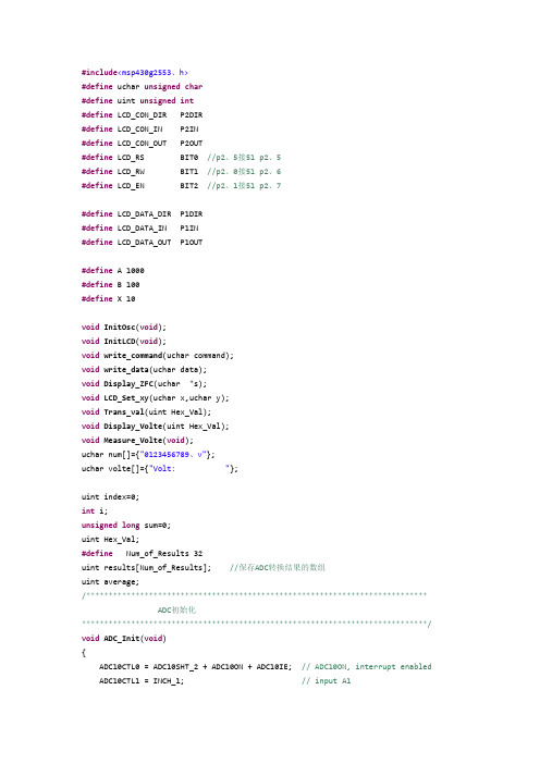
#include<msp430g2553、h>#define uchar unsigned char#define uint unsigned int#define LCD_CON_DIR P2DIR#define LCD_CON_IN P2IN#define LCD_CON_OUT P2OUT#define LCD_RS BIT0 //p2、5接51 p2、5#define LCD_RW BIT1 //p2、0接51 p2、6#define LCD_EN BIT2 //p2、1接51 p2、7#define LCD_DATA_DIR P1DIR#define LCD_DATA_IN P1IN#define LCD_DATA_OUT P1OUT#define A 1000#define B 100#define X 10void InitOsc(void);void InitLCD(void);void write_command(uchar command);void write_data(uchar data);void Display_ZFC(uchar *s);void LCD_Set_xy(uchar x,uchar y);void Trans_val(uint Hex_Val);void Display_Volte(uint Hex_Val);void Measure_Volte(void);uchar num[]={"0123456789、v"};uchar volte[]={"Volt: "};uint index=0;int i;unsigned long sum=0;uint Hex_Val;#define Num_of_Results 32uint results[Num_of_Results]; //保存ADC转换结果的数组uint average;/**************************************************************************** ADC初始化*****************************************************************************/ void ADC_Init(void){ADC10CTL0 = ADC10SHT_2 + ADC10ON + ADC10IE; // ADC10ON, interrupt enabled ADC10CTL1 = INCH_1; // input A1ADC10AE0 |= 0x02; //二次采集}/**************************************************************************** DCO时钟初始化设为1MHz*****************************************************************************/ void DCO_Init(void){if(CALBC1_1MHZ==0xFF||CALDCO_1MHZ==0xFF){while(1);}BCSCTL1 = CALBC1_1MHZ;DCOCTL = CALDCO_1MHZ;BCSCTL2 = SELM_0 +DIVM_0;}/****************************************************************************向12864发送字节*****************************************************************************/ void SendByte(uchar Zdata){uint i;for(i=0; i<8; i++){if((Zdata << i) & 0x80){LCD_CON_OUT |= LCD_RW; //clk始终信号为高}else{LCD_CON_OUT &=~LCD_RW; //clk始终信号为低}LCD_CON_OUT &= ~LCD_EN;LCD_CON_OUT |= LCD_EN;}}/****************************************************************************向12864写命令*****************************************************************************/ void write_command(uchar command){LCD_CON_OUT |= LCD_RS;SendByte(0xF8);SendByte(command & 0xF0);SendByte((command<<4)&0xF0);_delay_cycles(200);}/****************************************************************************向12864写数据*****************************************************************************/ void write_data(uchar data){LCD_CON_OUT |= LCD_RS;SendByte(0xFA);SendByte(data & 0xF0);SendByte((data << 4) & 0xF0);_delay_cycles(200);}void Display_ZFC(uchar *s){while(*s > 0){write_data(*s);s++;_delay_cycles(5000);}}/****************************************************************************确定12864屏幕显示的坐标位置(x,y)*****************************************************************************/ void LCD_Set_xy( uchar x, uchar y ){uchar address;switch(x){case 0: address = 0x80 + y; break;case 1: address = 0x80 + y; break;case 2: address = 0x90 + y; break;case 3: address = 0x88 + y; break;case 4: address = 0x98 + y; break;default:address = 0x80 + y; break;}write_command(address); //写入地址命令}/**************************************************************************** lcd初始化*****************************************************************************/ void InitLCD(void){LCD_CON_DIR |= 0xFF; //p2口定义为输出write_command(0x01); //清屏write_command(0x30);_delay_cycles(5000);write_command(0x0c);_delay_cycles(5000);}/****************************************************************************采集到的数据转化成电压形式*****************************************************************************/ void Trans_val(uint Hex_Val){unsigned long caltmp;uint Curr_Volt,volt,max;uint a[50];caltmp = Hex_Val;caltmp = caltmp*34600; //caltmp = Hex_Val * 34600Curr_Volt = caltmp >> 10 ; //Curr_Volt = caltmp / 2^nvolt = Curr_Volt;for(i=0;i<50;i++){a[i]=volt;}for(max=a[0],i=0;i<50;i++){if(a[i]>max)max=a[i];}Curr_Volt = max;Display_Volte(Curr_Volt);}/****************************************************************************主函数*****************************************************************************/ void main(void){WDTCTL = WDTPW + WDTHOLD;ADC_Init(); //ADC初始化DCO_Init(); //DCO初始化InitLCD(); //12864液晶初始化while(1){Measure_Volte(); //测量直流电压值并且显示}}/****************************************************************************测量电压*****************************************************************************/ void Measure_Volte(void){ADC10CTL0 |= ENC + ADC10SC; // Sampling and conversion start __bis_SR_register(CPUOFF + GIE);results[index++] = ADC10MEM; // Move resultsif(index == Num_of_Results){index = 0;for(i = 0; i < Num_of_Results; i++){sum += results[i];}sum >>= 5; //除以32Trans_val(sum);sum=0;}}/****************************************************************************显示电压值*****************************************************************************/ void Display_Volte(uint Hex_Val){uint Curr_Volt;Curr_Volt = Hex_Val;write_command(0x90);for(i=0;i<16;i++){write_data(volte[i]);}write_command(0x93);write_data(num[Curr_Volt / 10000]);write_data(num[10]);write_data(num[Curr_Volt % 10000/1000]);write_data(num[Curr_Volt % 10000 % 1000 / 100]);write_data(num[Curr_Volt % 10000 % 1000 % 100 / 10]);write_data(' ');write_data(num[11]);}/****************************************************************************ADC中断,进入低功耗模式关闭CPU*****************************************************************************/ #pragma vector=ADC10_VECTOR__interrupt void ADC10_ISR(void){__bic_SR_register_on_exit(CPUOFF); // Clear CPUOFF bit from 0(SR)}。
基于MSP430的智能仪表与组态王的通讯设计[1]
![基于MSP430的智能仪表与组态王的通讯设计[1]](https://img.taocdn.com/s3/m/7f7f46fbfab069dc50220117.png)
设计的监控系统中获得了成功运用。
关键词:智能仪表;组态王;亚当模块;多机通讯
中 图 分 类 号 : T P 391
文献标识Байду номын сангаас:B
Abstr act:The paper introduces a new communications project between Kingview and MSP430 SCM by adopting ADAM- 5000’s pro-
RS485 由 于 传 输 速 率 高 , 传 输 距 离 远 , 已 成 为 工 控 系 统 串 行 通 信 的 普 遍 形 式 。 当 采 用 RS485 实 现 上 位 机 与 下 位 机 串 行 通 信 时 , 由 于 上 位 机 通 常 只 提 供 RS232 串 行 接 口 , 因 此 需 要 使 用 RS232/RS485 通信接口进行转接, 在本文开发的监控系统中采 用了多串口卡来实现转换的。
ADAM- 5000 的协议, 实现了数据的实时采集、处理和显示。
2 系统结构
燃运皮带监控系统整体结构如图 1 所示。现场的各种传感 器 将 测 得 的 电 压 、电 流 、速 度 信 号 通 过 自 制 的 智 能 仪 表 传 送 给 上位机, 在组态界面上实时显示和监控皮带的运行状况;外部状 态输入是通过智能仪表检测电机接触器辅助触点的状态, 当信 号是闭合状态时系统的报警保护才起作用, 否则当检测到是开 路信号时, 采样值超出范围不报警, 继电器不动作;故障输出是 指电 机一 旦 过 流或 皮 带 堵煤 、皮 带 停转 、柱 销 断裂 等 故 障时 候 , 智 能 仪 表 发 出 脉 冲 信 号 送 给 PLC 传 送 至 1- 15# 牵 引 电 机 接 触 器和报警指示灯, 从而切断对应的接触器, 停止相应的电机, 同 时发出相应的声光报警信号。
基于MSP430单片机的多路电气量检测装置的设计

基于MSP430单片机的多路电气量检测装置的设计
廖从研;杜松怀;李春兰;黄俊
【期刊名称】《低压电器》
【年(卷),期】2010(000)001
【摘要】介绍了一种多通道电气量检测装置.该装置以单片机MSP430F1611为核心,由电源、模拟信号调理、数字信号输入、串行通信接口、人机交互接口及继电器输出接口电路组成,可获取研制新型剩余电流保护装置的实验数据.该装置电路结构简单,操作方便,易维护.
【总页数】3页(P17-19)
【作者】廖从研;杜松怀;李春兰;黄俊
【作者单位】中国农业大学,北京,100083;中国农业大学,北京,100083;中国农业大学,北京,100083;新疆农业大学,新疆,乌鲁木齐,830052;中国农业大学,北京,100083【正文语种】中文
【中图分类】TP216
【相关文献】
1.基于MSP430单片机的信号检测装置的设计与实现 [J], 张利;任俊玲;张芳
2.基于MSP430单片机的新型多路数字电压表设计 [J], 郝海燕
3.基于MSP430单片机的电导率检测装置的设计 [J], 蒋兴东;曾水平
4.基于MSP430单片机的电池组检测装置设计 [J], 张文文;徐航;朱浩然;姚璇
5.基于MSP430单片机的电池组检测装置设计 [J], 张文文;徐航;朱浩然;姚璇
因版权原因,仅展示原文概要,查看原文内容请购买。
基于MSP430数字式电压表

0・100
0.108
0.300
0.296
0.700
0.694
0.801
0.791
1.000
0.991
3.000
2.993
000
9.009
11.001
11.006
13.003
13.026
16.504
16.500
1.误差分析
通过分析以上测试数据,得出一下结论由表中数据和图例 可以看出电压测量分辨率V0.01V,通过统计求均值可得出测量误 差<1%。达到了设计要求。测量值与实际值有一定的误差,并且 误差随着输入电压的增大而变大。 其原因是输入电路中由电阻串 联构成来实现分压,电阻参数的变化及负载效应会引起分压比的 误差;运算放大器本身存在漂移和噪声, 开环增益和开环输入电 阻不无穷大,因此会引入误差。由图例不难看出输入电压不是线 性的,且随着输入电压增大,误差也变大,这说明信号源输入电 压给电路,由于电路本身输入阻抗不够高,电路会向信号源索取
#in clude "LCD_driver/Template_Driver.h"
#include "images/images.h"
#in clude "driverlib.h"
******************************************************************
六、结论
经过一段时间的努力,基于单片机的简易数字电压表基本完 成。但设计中的不足之处仍然存在。 这次设计是我第一次设计电 路,在这过程中,我对电路设计,单片机的使用等都有了新的认 识。通过这次设计熟练了软件的使用方法,积累了不少经验。。
基于MSP430单片机的低功耗数字式直流电压表设计(优.选)
课程设计(论文)说明书题目:基于MSP430单片机的低功耗数字式直流电压表设计院(系):信息与通信学院专业:电子信息工程学生姓名:学号:指导教师:武小年职称:副教授2012年12月 6 日摘要随着电子信息产业智能化的不断发展,单片机微控制器在工作领域等到了广泛的应用。
在电子产品实现智能化的同时,人们对绿色环保的要求也越来越高。
本设计从功耗的角度出发,采用TI公司的MSP430G2553混合信号微控制器作为系统核心设计的直流电压变,使用OLED液晶显示,结合简单的外围电路实现电压的采集,量程选择,数值显示等功能。
经实验证明,该电压表具有设计方法合理,简单易行,功耗低,测量精度高及携带方便等特点,适合很多电压直流电路电压的测量。
关键词:混合信号微控制器、电压表、低功耗Abstract:With the continuous development of the electronic information industry intelligent, single-chip microcontroller until the wide range of applications in the areas of work. Realize intelligent electronic products at the same time, people are increasingly high requirements for green. The design from the perspective of power consumption, using TI the company's MSP430G2553 mixed signal microcontroller as the core of the system design variable DC voltage, OLED LCD display, combined with simple peripheral circuit voltage acquisition, range selection, numerical display .The experiment proved that the voltmeter has reasonable design method is simple, low power consumption, measurement of high precision and easy to carry, suitable for many voltage DC circuit voltage measurements.Key words:Mixed-signal microcontroller, voltmeter, low power consumption目录引言 (1)1 设计方案 (1)1.1 设计要求 (1)1.2 数字式直流电压表设计分析 (1)2 硬件电路设计 (2)2.1 主要器件介绍 (2)2.1.1 MSP430G2553 (2)2.1.2 OLED显示屏 (3)2.2硬件电路原理分析 (4)2.2.1整体硬件原理图 (4)2.2.2电源电路设计分析 (4)2.2.3 单片机最小系统设计分析 (5)2.2.4 OLED显示接口电路分析 (5)2.2.5 量程选择电路接口分析 (6)3 程序设计 (6)3.1主函数 (6)3.2 系统初始化函数 (7)3.2 ADC初始化函数 (7)3.3OLED屏初始化 (7)4 数据测量 (8)4.1电源稳压电路输出电压 (8)4.2电压检测测试 (8)5 心得体会 (9)谢辞 (10)参考文献 (11)附录 (12)引言在电量的测量中,电压、电流和频率是最基本的三个被测量,其中电压量的测量最为经常。
基于MSP430的简易阻抗测量仪设计
基于MSP430的简易阻抗测量仪设计作者:李乐乐肖园汤轲来源:《科技视界》 2013年第2期李乐乐肖园汤轲(南京信息工程大学电子与信息工程学院,江苏南京 210044)【摘要】介绍一种数字化的简易阻抗测量仪设计方法,以MSP430单片机作为控制核心、CPLD进行数字信号处理,DDS信号发生器提供输入信号,通过高速A/D转换器AD7799,实现信号实时采样、数据处理和液晶显示,键盘做功能设置。
该设计实现了RLC元件参数的实时测量、自动识别、结构判断和谐振频率测试等功能。
测试结果表明该系统具有测试精度高、频率范围宽、可靠性好和性价比高等优点。
【关键词】阻抗测量仪;MSP430;CPLD;AD7799Simple Impedance Measuring Instrument is Designed Based on MSP430LI Le-le XIAO Yuan TANG Ke(Nan Jing University of Information Science and Technology, Nanjing Jiangsu,210044, China)【Abstract】A design method of simple digital impedance measuring apparatus is introduced, with MSP430 single chip microcomputer as control core, CPLD, digital signal processing, DDS signal generator provides the input signal, AD7799 through high-speed A/D converter, signal real-time sampling, data processing and liquid crystal display, keyboard do feature set. This design has realized the RLC component parameter real-time measurement, automatic identification, structure and function such as resonance frequency test. Test results show that the system has high measurement precision, wide frequency range and good reliability and high cost performance, etc.【Key words】Resistance measuring instrument;MSP430;CPLD;AD77990引言阻抗测量仪是一种用途很广泛的电子测量仪器。
基于MSP430的电阻测量系统的设计
基于MSP430的电阻测量系统的设计摘要在仪器仪表应用领域中,电阻测量是一个比较普遍的要求。
本系统将介绍采用MSP430单片机实现电阻测量系统。
本设计基于单片机技术原理,以MSP430单片机芯片作为核心,用点阵式液晶显示芯片LCD1602完成液晶显示功能,增加了显示的美观性与直观性;有电流源电路、放大器电路、跟随器电路组成的恒流源作为电源为MSP430单片机提供稳定的电流;在模拟信号采集和输出模块中运用TI公司生产的PGA204可编程增益仪表放大器,使产品实现了高精度、微功耗以及微小型封装的完美组合,对模拟信号进行前置滤波放大,减小无用信号的干扰,提高了稳定性。
本系统的大部分功能通过软件编程来实现,LCD显示功能,提供了友好的人机交互界面,能适合各种工作场合。
关键词:MSP430单片机,1602芯片,PGA204芯片,电阻测量,恒流源The Design of Resistance Measurement Systembased on MSP430ABSTRACTThe instruments used in the field of resistance and the measurement is a more popular demand. this system will introduce the MSP430 monolithic integrated circuits for resistance measurement system.This design revivification theory to MSP430 monolithic integrated circuits, with a chip as a core four-three-three formation LCD display chip LCD1602 through liquid crystal display the functions, and visualization and display of current ; a circuit or circuit, an amplifier with the constant flow of electrical power source as for the supply of the current monolithic integrated circuits MSP430,The signal collecting and output of a module of the use of programmatic PGA204 gain appearance of an amplifier, the product of high precision, a small package TDP and perfect combination of a signal, which filtering, less interference fromno signal, and improves stability.The system of functional programming by software to implement and LCD display provides functionality and friendly man-machine interaction and interface to the workplace.KEY WORDS: MSP430 monolithic integrated circuits,1602 chip,PGA204 chip,measurement of resistance,constant current source目录前言 1第1章系统的总体设计方案 21.1 设计概要 21.1.1 系统的设计特点21.1.2 系统的主要组成21.1.3 系统的总体电路框图 2第2章系统的硬件设计 42.1 单片机系统 42.1.1 MSP430结构概述 42.2.2 MSP430F14X系列单片机的介绍 52.1.2 MSP430F14X系列的A/D转换62.1.3 MSP430单片机的最小系统电路72.2 恒流源部分92.2.1 电流源92.2.2 放大器92.2.3 跟随器112.3 LCD显示部分112.3.1 1602芯片简介112.3.2 显示电路132.4 时钟电路142.4.1 S-3530A芯片的特性14 2.5电源电路16第3章系统软件设计183.1 初始化程序设计183.1.1 端口初始化 183.1.2 A/D初始化193.1.3 定时器A的初始化20 3.2 A/D采集程序213.3 显示模块流程图223.4 测试程序24结论29谢辞30参考文献31附录33外文资料翻译37前言在科学研究和工程应用中,我们经常会遇到需要进行电阻测量的场合,传统的方法是伏安法,这种方法需同时测电压和电流,所以系统误差较大。
基于DSP与430单片机的电能质量测量仪设计
Abstract……………………………………………………………………………………………………………………….II
第一章 绪论………………………………………………………………………………….1 1.1选题背景……………………………………………………………………………….1 1.2电能质量的相关概念及研究意义…………………………………………………….1 1.2.1电能质量的相关概念…………………………………………………………..1 1.2.2电能质量问题的危害…………………………………………………………..2 1.2.3电能质量分析测量系统的研究意义…………………………………………….3 1.3国内外研究现状……………………………………………………………………….3 1.4本课题主要的研究内容和章节安排………………………………………………….5 第二章 电能质量主要参数的算法现实……………………………………………………6 2.1电能质量主要参数分析………………………………………………………………6 2.1.1电压偏差…………………………………………………………………………6 2.1.2频率偏差………………………………………………………………………..6 2.1.3三相电压不平衡度……………………………………………………………。7 2.1.4电压波动和闪变………………………………………………………………..7 2.1.5公用电网谐波…………………………………………………………………。8 2.2电能质量参数的测量原理及算法现实……………………………………………..10 2.2.1电压、电流、功率的测量原理及实现方法…………………………………10 2.2.2频率的测量原理及实现方法……………………………………………。…..11 2.2.3谐波的测量原理及实现方法…………………………………………………12 2.3本章小结………………………………………………………………………………12 第三章 系统的硬件设计…………………………………………………………………。13 3.1系统硬件设计原理框图………………………………………………………………13 3.2信号采集模块…………………………………………………………………………13 3.2.1电压、电流传感器……………………………………………………………13 3.2.2硬件滤波电路………………………………………………………………….15 3.2.3信号调理电路…………………………………………………………………。15 3.2.4 AD转换电路…………………………………………………………………。16 3.2.5信号采集模块的电源电路……………………………………………………17 3.3 DSP信号处理模块……………………………………………………………………18 3.3.1 TMS320C5410A简介…………………………………………………………………………….18 3.3.2多通道缓冲串口(McBSP)…………………………………………………19 3-3.3增强型主机接口(HPI.8)……………………………………………………20 3.3.4外扩存储器设计………………………………………………………………20 3.3.5 DSP系统模块的电源电路……………………………………………………2l 3.4 430单片机控制模块…………………………………………………………………22 3.4.1 MSP430单片机简介……………………………………………………………22 3.4.2液晶显示与按键输入…………………………………………………………23 3.4.3其它外围功能器件…………………………………………………………….24 3.4.4 MSP430系统模块的电源电路………………………………………………..25 3.5硬件实物照片………………………………………………………………………。26
- 1、下载文档前请自行甄别文档内容的完整性,平台不提供额外的编辑、内容补充、找答案等附加服务。
- 2、"仅部分预览"的文档,不可在线预览部分如存在完整性等问题,可反馈申请退款(可完整预览的文档不适用该条件!)。
- 3、如文档侵犯您的权益,请联系客服反馈,我们会尽快为您处理(人工客服工作时间:9:00-18:30)。
c o mp l e me n t e d b y t h e e x t e r n a l v o l t a g e d i v i d e r n e wo t  ̄ v o l t a g e c o l l e c t i o n n e wo t  ̄ c u r r e n t c o l l e c t i o n
2 0 1 3 年第5 期
文章编号 : 1 0 0 9— 2 5 5 2 ( 2 0 1 3 ) 0 5— 0 1 8 1 — 0 4 中图分类号 : T M 9 3 2 文献标识码 : A
基 于 MS P 4 3 0设 计 多 路 电压 电 流 测 量 仪
马 颖
( 四川信息职业技术学院 ,四川 广元 6 2 8 0 4 0 )
0 引言
随着社 会 的发 展 , 电子 仪 表 的 普 及 , 原 先 大 体
关键词 :M S P 4 3 0 ;液晶显示;高精度数据采集 ;自 动转换
De s i g n o f mu l t i - c ha n n e l v o l t a g e a n d c u r r e n t me a s u r i n g i n s t r u me n t b a s e d o n MS P4 3 0
d i s p l a y mo d u l e s , s u c c e s s f u l i mp l e me n t a t i o n o f a u t o ma i t c r a n g e — c h a n g i n g c i r c u i t , f o u r — c h a n n e l s i mu l t a n e o u s me a s u r e me n t d a t a,d i s p l a y o f t w o - c h a n n e l v o l t a g e ,t wo — c h a n n e l c u re n t .U s e d MC U wi t h 1 2 b i t u l t r a h i g h — s p e e d A/ D c o n v e r t e r i t e n a b l e s h i g h — a c c u r a c y d a t a a c q u i s i i t o n s y s t e m f u l l y f u n c t i o n a l ,
n e t wo r k,a ut o ma t i c r a n g e s wi t c hi n g d a t a n e t wo r k, s i g n a l n e t wo r k s ,1 2, 8 6 4 d o t ma t r i x l i q u i d c r y s t a l
i ns t r u me n t .
Ke y wo r ds : MS P4 3 0; l i qu i d c ys r t a l d i s p l a y; h i g h pr e c i s i o n d a a t a c q u i s i io t n; a ut o ma t i c c o n v e r s i o n
MA Yi n g ( S i c h u a n I n f o r ma t i o n T e c h n o l o g y C o l l e g e , G u a n g y u a n 6 2 8 0 4 0 , S i c h u a n P r o v i n c e , C h i n a)
un r ni ng s t a bi l i t y,s c a l bi a l i t y,s t r o ng,S O t ha t t h e wh o l e i n s t r u me n t p o we r c o n s u mp t i o n i s v e r y l o w,i n l i ne wi h t t he c h a r a c t e r i s t i c s o f e n e r g y — s a v i n g e n v i r o n me n t a l pr ot e c t i o n, s u r v e y i ng nd a c o n v e n i e n t h a n d h e l d
摘
要 :多路 电压 电流测量仪 以 MS P 4 3 0为控 制核 心 ,辅 以外部 分压 网络 、 电压采 集 网络 、电流
采集 网络 、 自动量 程数据 切换 网络 ,信 号放 大 网络 、1 2 8 6 4点阵液 晶 显示模 块 、成功 地 实现 了 自
动 量程 转换 , 四路数 据 同时 测 量 ,显 示 两路 电压、 显 示 两路 电流 。利 用 MC U 自带的 1 2 b i t 超 高 速A / D转换 器实现 了高精度 数据 采集 , 系统 功 能 完善 、运行 稳 定 、 可扩展 性 强 ,使 整 个仪 表 功 耗 极低 ,符 合手持仪 表 节能环 保 、测量便 捷 的特点 。