05激光粒子计数器URS精编版
Microtrac S3500 用户手册说明书

Microtrac Retsch GmbH Function & Features Downloads Versions & Accessories Request a quote MicrotracProductsParticle Size & Shape AnalysisLaser DiffractionS3500 The Microtrac S3500 is a industry-preferred Laser Diffraction (LD) analyzer, ideally suited for various particle characterization tasks. It is the first particle size analyzer that uses three precisely placed red laser diodes to accurately characterize particles like never before. The patented Tri-Laser System provides accurate, reliable and repeatable particle size analysis for a diverse range of applications by utilizing the proven theory of Mie compensation for spherical particles and the proprietary principle of Modified Mie calculations for non-spherical particles. The S3500 measures particle size from 0.02 to 2,800 µm. Features Tri–laser, red, multi-detector, multi-angle optical system Algorithms that utilize Mie compensation and Modified Mie calculations for non-spherical particles Measurement capability from 0.02 to 2,800 µm Wet and dry measurements Enclosed optical path ensures complete protection of the optical components leading to little or no operator intervention Product Advantages Utilizing three red lasers, increases the range of measurement, giving you the flexibility to conduct analysis on a wide range of samples Proprietary Modified Mie calculations allow users to accurately measure complex particles that other particle analyzer struggle to accurately characterize Seamless transition from wet to dry measurement reduces down time Fixed detectors provide rugged durability and assure proper positioning Small bench footprint reduces demand on valuable laboratory space Particle Size and Shape Analyzer S3500 Reviews from our customers "The S3500 has awesome image analysis capability. Using this instrument we have obtained high quality results. "Manik P. K. MaheswaramAmerichem "Very easy to use system that provides consistent results. The S3500 has some good features and the customer service is great. "Robert GilmoreSavannah River Nuclear Solutions "Microtrac gives constant robust results. "Jean-Francois GrenierCoalia - Thetford Mines "Laser-diffraction-based particle size analyzer, very accurate in wet as well dry method of operation, very wide range 0.02-2000 micron. Highly recommended for mining and research industry."Basant RathNational Mineral Development Corp. "Flex software to operate with S3500 is helpful and easy for all operators to set up parameters, use the testing program and get values of data clearly for printing out for saving for the next tests. "Kiet NguyenNQA Equipment & Chemicals "Instrument was sent in for service - Service/Technical Support Team kept me informed of the progress, and the repair was completed in a timely manner. After-service support was excellent, back up and running with the "new" software same day of delivery."Justin LloydTechnic Inc Trusted reviews provided by Typical Applications Used in various fields such as: beverages, biotechnology, chemicals, food, medicine / pharmaceuticals, metal powders, metals, pigments, geology / metallurgy, ... To find the best solution for your particle characterization needs, visit our application database Measuring range0.02 µm 2.8 mmMeasuring principleLaser diffractionLasers3x Red 780 nmLaser power3 mW nominalDetection systemTwo fixed photo-electric detectors with logarithmically spaced segments placed at correct angles for optimal scattered light detection from 0.02 to 165 degrees using 151 detector segments.DataVolume, number and area distributions as well as percentile and other summary dataData formatStored in ODBC format in encrypted Microsoft Access Databases to ensure compatibility with external statistical software applications.Data integrityData integrity may be ensured using FDA 21 CFR Part 11 compliant security features including password protection, electronic signatures and assignable permissionsMeasuring time~ 10 to 30 secondsPower requirementsAC input: 90 - 132 VAC, 47 - 63 Hz, single phase 200 to 265 VAC, 47 - 63 Hz, single phasePower consumption25 W nominal, 50 W max. (depending on options installed)Environmental conditionsTemperature: 5° to 40° Celsius (50° to 95° Fahrenheit) Humidity: 90% RH, noncondensing maximum Storage temperature: -10° to 50° Celsius (14° to 122° Fahrenheit) (dry only) Pollution: Degree 2Physical specificationsCase Material: Steel and impact resistant plastic Exterior surfaces are finished with corrosion resistant paint or platingDimensions (W x H x D)~ 560 x 360 x 460 mm (22 x 14 x 18 in)Weight~ 27 kg (60 lbs )Eductor air supply100 psi (689 kPa) maximum pressure 5 CFM (8,5 m3/h) at 50 psi (345 kPa) minimum flow rate Free of dry contaminants, moisture and oilVacuumVacuum must exceed 50 CFM Content may be subject to modifications or corrections © 2023 Microtrac Retsch GmbH We will not sell or share your email with anyone outside of REUZEit
Extech 仪器 VPC300 粒子计数器与相机用户手册说明书

USER MANUALVideo Particle Counter with built‐in CameraModel VPC300Additional User Manual Translations available at IntroductionThank you for selecting the Extech Instruments Model VPC300 Particle Counter with Camera.The VPC300 has a Color TFT LCD display, a 74MB internal data storage bank, a micro‐SD memory card slot for capturing images and video for viewing on a PC, and a built‐in 320x240 pixel camera for capturing stills/video of test locations. The VPC300 offers quick and accurate readings for particle count, air temperature, most surface temperatures, and relative humidity. The VPC300 also offers a Dew Point and Wet Bulb temperature calculation geared for energy efficiency and environmental protection applications. Supplied PC software allows the user to generate reports based on records data, images, and video.This device is shipped fully tested and calibrated and, with proper use, will provide years of reliable service. Please visit our website () to check for the latest version of this User Guide, Product Updates, and Customer Support.Features∙ 2.8” TFT Color LCD display∙Convenient keystroke menu structure for measurements, setup, and other programming ∙320 x 240 pixel built‐in camera for still and video imaging∙JPEG images and 3GP video∙Meter’s internal memory 74MB.∙Meter can store 5000 records (date, time, counts, humidity, temperature, sample volumes, and location label) and 20 minutes of video to internal memory.∙Micro‐SD memory card slot (8GB maximum); card not included.∙Selectable Test sample time, count data, and programmable delay∙Simultaneously measure and display 6 channels of particle sizes (down to 0.3μm)∙Air temperature and relative humidity∙Dew point and Wet bulb temperature calculations∙MIN/MAX/AVG/DIF record with date/time stamp∙Auto power off∙Language selection for English, French, German, and Spanish∙Meter is shipped NIST calibrated with calibration certificate∙Tripod mounting option∙Includes universal AC adaptor/charger with a variety of plug options, USB cable, PC software, tripod, Zero count filter, 7.4V Lithium‐ion polymer rechargeable battery, and protective caseMeter Description1.Isokinetic probe2.Temperature and RH Sensor (note its protective cover that slides up and down)3.Color TFT LCDpartment for USB interface port and AC Adaptor/Charger5.Function F1, F2, F3 buttons6.Control buttons: Page Up/Down, Enter, Run/Stop, and ESC7.ON/OFF button8.Battery and Micro‐SD card compartment (SD card slot underneath battery)9.Tripod mount10.Camera lens3OperationPower ON‐OFFPress and hold the power button to switch the instrument ON orOFF.Important NotesNote: Operating the particle counter with the isokinetic probe cap inplace will damage the pump and other internal components.Note:Electrical noise, sensor leakage, or other interference maycause the VPC300 to show incorrect particle count data.Getting StartedWhen the meter powers ON, the Particle Counter icon is displayed at the center of the LCD and the date, time, and battery status can be observed on the top row of the LCD. Three bottom row options are also displayed and can be selected using the Function keys (F1, F2, and F3) as shown below. These are explained in greater detail later in this user guide:Memory (where data, images, and video are located)System Setup ParametersHelp FileSymbol GlossaryCumulative mode Video Record startConcentration mode Video modeTest is pausedColor coded particle scale (green islow, yellow is moderate, and red ishigh particle count)CAM (Camera) modeAlarm ONDifferential mode Battery StatusTest is running Particle Count SetupSequence of OperationTo ensure that you measure the amount of particles accurately, perform this sequence of operation.1.Zero the particle count sensor2.Setup your counter for proper operation. Sample time, mode, cycle, and interval.3.Run your test cycles and evaluate the results.Basic OperationPress and hold the ON/OFF button for 3 to 5 seconds until the display illuminates to power on the meter.Press the enter button ()to get to setup mode.Press F3 to enter settings mode.Set each parameter to your preferred setting by pressing ENTER to enter each parameter. Then press ENTER to enable editing of each parameter. Press ESC to exit parameter setup.Sample Time: Length of time each test runs (3 to 60 seconds)Start Delay: Duration of time from RUN to actual start of test. (3 to 100 seconds)Channel Display: Particle sizes displayed during test.Ambient Temp/RH: Allows the display of the air temp and %RH valuesSample Cycle: Number of test cycles to run (1 to 100)Sample Mode: Cumulative, differential, concentrationInterval: Test cycle delay measured in seconds.Level Indication: Particle level selection (highlighted on display)Press ESC to return to testing screenPress RUN/STOP to start the automated test sequence.Taking MeasurementsAfter powering the meter, press the Enter () button to accessthe Particle Measurement screen. Then open thetemperature/RH sensor by sliding its protective coverdownward.When measuring particle counts, theseicons correspond to the function keys (F1,F2,F3).F1 is to enter Camera and video mode, F2 is to view your saveddata, and F3 is for Setup mode.The display will show the particle count channels with readings,air temperature (AT), Dew point temperature (DP), Wet bulbtemperature (WB), and Relative Humidity (%RH) as shown inaccompanying diagram.Press the RUN/STOP button to start the air pump and the particle count measurementprocess. When the programmed sampling time has elapsed, the particle measurement cycle will automatically end and the measurement data will be automatically stored. To set thesampling time, refer to the Particle Count SETUP MODE section. If desired, press theRUN/STOP button and stop the session manually.When measuring particle counts, these icons correspond to the function keys (F1,F2,F3). F1 is to enter Camera and video mode, F2 is to view your saved data, and F3 is for Setup mode.Capturing ImagesWhile measuring particle counts, press F1 to enter the camera mode. Press F1 to capture a Still image. Then press F1 to Save the image or F3 to delete it. Press ESC to get back to exit this mode.Capturing VideoWhile measuring particle counts, press F1 to enter the camera mode. Press F3 to enter the video mode. The LCD will show . Now press F2 to capure video and pressF2 again to stop the video capture. The video file will be automatically stored. The System Setup mode section allows the user to store video to the meter’s internal memory or to an installed Micro‐SD card. Press ESC to exit this mode.Particle Counter Setup ModeWhen measuring, these display icons are visible. PressF3 to enter the Setup mode. Use the up and down arrow keys to selectan option to edit and press ENTER () to access the selection.SAMPLE TIME (Test Cycle Time)Select Sample Time. Press the Enter () button to enter the optionand Press Enter again to activate the setting for editing. Use the arrow buttons to set thesampling time/gas volume (3 to 60 seconds). Use the Esc button to saveand return to the menu.START DELAYThe test start delay time is adjustable (3 to 100 seconds). From the Particle setup menu, use the Up and Down arrows to select Start Delay. Press the Enter () button to enter the option and Press Enter again to activate the setting for editing. Use the arrow keys to select the desire delay time. The test will not start until the programmed delay time has elapsed. Use the Esc button to save the setting and to return to the menu.CHANNEL DISPLAYSelect channels that are to be displayed. From the Particle setup menu, use the Up and Down arrows to select Channel Display. Press the Enter () button to enter the option. Use the arrow keys to select the channel and press the Enter key to select or de‐select the channel. Use the Esc key to save the setting and to return to the menu.AMBIENT TEMPERAURE / %RHEnable or Disable the ambient temperature and relative humidity displays. From the Particle setup menu, use the Up and Down arrows to select Ambient Temp/RH. Press the Enter () button to enter the option. Use the arrow keys to select Enable or Disable and use the ESC button to save and return to the menu.SAMPLE CYCLESet the desired number of test cycles to run. From the Particle setup menu, use the Up and Down arrows to select Sample Cycle. Press the Enter () button to enter the option and Press Enter again to activate the setting for editing. Use the arrow keys to select the number of cycles to run the test (1 to 100). Press ESC to save setting and to return to the menu.SAMPLE MODESelect desired mode (Cumulative, Differential, or Concentration). From the Particle setup menu, use the Up and Down arrows to select Sample Mode. Press the Enter () button to enter the option. Use the arrow buttons to select desired mode and then use ESC to save and to return to the menu.Cumulative Mode – measures all particles that are greater than or equal to the particle size selected in the Sample Volume field.Differential Mode – measures all particles that are greater than or equal to the particle size selected in the Sample Volume field, but less than the next largest particle size.Concentration Mode – used to take a quick sample of airborne particulates, performed especially in areas where the particulate levels are unknown and may exceed the operating levels of this counter.INTERVAL (TIME BETWEEN REPEATED TEST CYCLES)Set the time between tests for tests with more than one cycle (1 to 100 seconds). From the Particle setup menu, use the Up and Down arrows to select Interval Time. Press the Enter () button to enter the option and Press Enter again to activate the setting for editing. Use the arrow buttons to set the desired interval time. Use the ESC button to save setting and to return to the menu. Note: The INTERVAL setting is only for programming the time between test cycles, not between individual measurements.LEVEL (ALARM LIMIT) INDICATIONSelect the Alarm Limit (Level) of the corresponding particle size. When the selected particle size is exceeded, the instrument alerts the user. From the Particle setup menu, use the Up and Down arrows to select Level Indication. Press the Enter () button to enter the option. Use the arrow buttons to select the desired alarm limit and then press ESC to save setting and return to the menu.Memory Storage BrowserWhen the meter is switched ON, these LCD icons arevisible. Press F1 to enter the data memorysection. There are three options available in the memory mode,Picture, Video, and Particle Logs.Use the arrow buttons to select one and then press ENTER () toaccess the selection.When browsing images, data, and video use the arrow buttons tonavigate, use the Enter button to select, and use the ESC or F3button to return to the menu.Press ESC again to exit to the power‐on screen.System Setup ParametersWhen the meter is switched ON, these LCD icons are visible. Click on the F2 key and the menu will appear. Detailed explanations are provided below for each parameter.Use the Arrow keys to choose the desired parameter.DATE/TIME Set the Date and Time. Press the Enter () button to open theselection for editing. Use the arrow keys to change a value, and usethe Enter button to go to the next item. Press the ESC button to savethe setting return to the Setup menu.FONT COLOR Select the color for the Display font. Press the Enter () button toopen the selection for editing. Use the arrow keys to select a colorand use the ESC button to save the setting and return to the Setupmenu.LANGUAGE Select the desired language for menu text. Press the Enter ()button to open the selection for editing. Use the arrow keys to selecta language and use the ESC button to save the setting and return tothe Setup menu.BRIGHTNESS Adjust the display to the desired brightness level. Press the Enter() button to open the selection for editing. Use the arrow keys toselect a level and use the ESC button to save the setting and return tothe Setup menu.AUTO POWER OFF Select elapsed time value before meter switches OFF. Press theEnter () button to open the selection for editing. Use the arrowkeys to select the setting and use the ESC button to save the settingand return to the Setup menu.DISPLAY TIME‐OUT Select display auto‐off delay. Press the Enter () button to open theselection for editing. Use the arrow keys to select a setting and usethe ESC button to save the setting and return to the Setup menu.MEMORY STATUS Display the memory and the micro‐SD card status. Press the Enter() button to open the selection for editing. Use the arrow keys toselect ‘Device’ or ‘SD Card’ and then view the status for the selecteditem. Use the ESC button to return to the Setup menu.FACTORY DEFAULT Restore factory default settings. Press the Enter () button to openthe selection for editing. Use the arrow keys to select YES or NO andthen use the ESC button to save the setting and return to the Setupmenu.UNITS Select the desired unit of measure for temperature C or F. Press theEnter () button to open the selection for editing. Use the arrowkeys to select the Unit and use the ESC button to save the setting andreturn to the Setup menu.Zero the Particle count SensorParticles must be purged (removed) from the sensor before and after each use in a high sample count environment.Zero the sensor:1.Unscrew and remove the Isokinetic probe and attach the Zero count filter.2.Turn on the meter and in the Setup mode,a.Set the Sample mode to Cumulative.b.Set the Channel Display to ensure all channels are selected.c.Set Sample time to 60 secondsd.Set Sample Cycle to 103.Start the meter4.Allow the meter to run until all of the particle counts read zero. You may need torun the meter multiple times to ensure that all channels read zero.5.Turn off the meter.6.Remove the Zero count filter and attach the Isokinetic probe.Particle Count TableParticle count readings, grouped by color, Green (good), Yellow (caution), and Red (hazard), are shown for each channel.Channel Green Yellow Red0.3um 0 to 100,000 100,001 to 250,000 250,001 to 500,0000.5um 0 to 35,200 35,201 to 87,500 87,501 to 175,0001.0um 0 to 8,320 8,321 to 20,800 20,801 to 41,6002.5um 0 to 545 546 to 1,362 1,363 to 2,7245.0um 0 to 193 194 to 483 484 to 96610.0um 0 to 68 69 to 170 171 to 340 Note: This table is intended for reference use onlyParticle Counter ConsiderationsParticle pollution is a mixture of various components including smoke, dust, chemicals, mold, and gases. Particle concentrations can affect our health and comfort levels. Evaluating the quality of the air by determining the concentration and size of these particles can help to determine if a problem exists. Locating the source of these various particles can help to determine effective methods of reducing these and improving the Indoor Air Quality (IAQ).One way to determine the source of air particulates in a room is to test the air outside of the room under investigation. Determine the concentration and size of particulates at the air intake to that room. Purge or Zero the particle counter and then measure the concentration and size of particles in multiple areas of the room to be tested, to determine the effectiveness of the incoming air filtration. The air temperature, relative humidity, and CO2 levels are also an important consideration for IAQ as high humidity and lower temperatures can bring about mold creation.If a room is classified as an ISO clean room or clean zone, the counts of particle sizes for that class cannot be exceeded when tested.Refer to the ISO Clean Room Class chart (ISO 14644‐1:1999) for values.The VPC300 is equipped with a still/video camera to directly see the areas under test. Data, images, and video can be stored on up to an 8GB micro‐SD card (not included) or in the meter’s internal 74MB memory.The life of the meter can be maximized by testing only when necessary and securely storing the instrument when it is not in use. Continuous use is not recommended and can shorten the life of the instrument especially in dusty environments. Setting up a common sense maintenance schedule and testing to the schedule will go a long way in lengthening the life of the instrument sensor.PC Interface and Supplied PC softwareThis meter has the capability to connect to and communicate with a PC. A USB cable is supplied and connects to the jack on the meter’s left side compartment.To install and use the software, please refer to the instructions provided on the supplied CD‐ROM and/or the instructions provided in the HELP Utility within the software program. Check the software download page of the website for the latest version of the PC software and its operating system compatibility.Battery Charging and ReplacementWhen the battery icon appears drained on the LCD or if the meter will not switch ON, the battery must be recharged using the supplied AC adaptor/charger. The charger plug connects to the jack located on the meter’s left side compartment.The battery compartment is located on the rear of the instrument.The battery is a 7.4V Lithium‐ion polymer rechargeable battery.To access the meter’s battery for replacement:1.On the rear of the meter, remove the Phillips head screw that secures the batterycompartment.2.Open the compartment by carefully lifting the compartment cover.3.Replace the battery with one of the same type (note that the Micro‐SD card slot islocated underneath the battery as explained below).4.Close the compartment and secure the compartment cover with the Phillips head screwBattery Safety Reminderso Please dispose of batteries responsibly; observe local, state, and national regulations.o Never dispose of batteries in fire; batteries may explode or leak.o Always install a new battery of the same type.Micro‐SD Card Slot (optional)The micro‐SD card slot is located inside the battery compartment underneath the battery. Micro‐SD cards up to 8GB can be inserted in the slot.To access the SD memory card slot:1.Turn off power to the meter and remove the AC adapter cable if connected.2.Open the battery compartment as described in the battery replacement section.3.Remove the battery.4.Insert a micro‐SD card (8GB max.) in the card slot underneath the battery by lifting up onthe metal card holder and placing the Micro SD card in the connector. The pins facingtowards the top of the meter. Close the metal holder.5.Insert the battery and secure the compartment cover before powering on the meter.SpecificationsParticle CounterChannels Six channels: 0.3, 0.5, 1.0, 2.5, 5.0, 10μmFlow Rate 0.1ft3/min (2.83L/min)Counting Efficiency 50% at 0.3μm; 100% for particles > 0.45μmCoincidence Limit (Coincidence Loss) 5% at 2,000,000 particles per ft3Particle Count Modes Cumulative, Differential, and Concentration modesAir Temperature and Relative Humidity MeasurementsAir Temperature Range 32 to 122o F (0 to 50o C)Dew Point/Wet Bulb Temperature Range 32 to 122o F (0 to 50o C)Relative Humidity Range 0 to 100%RHAir Temperature Accuracy ±0.9o F (0.5o C) 50 to 104o F (10o C to 40o C)±1.8o F (1.0o C) all other rangesDew Point/Wet Bulb Temperature Accuracy ±0.9o F (0.5o C) 50 to 104o F (10o C to 40o C)1.8o F (1.0o C) all other rangesRelative Humidity Accuracy ±3%RH from 40 to 60%RH±3.5%RH from 20 to 40%RH and from 60 to 80%RH ±5.0%RH from 0 to 20%RH and from 80 to 100%RHGeneral SpecificationsDisplay 2.8” 320 x 240 pixel TFT Color LCD with backlight Low battery indication Battery symbol appears on the LCDMicro‐SD Card Slot Accommodates up an 8GB cardMeter internal memory 5000 sample records; 74MBPower supply Rechargeable 7.4V Lithium‐ion polymer batteryBattery life Approx. 4 hours of continuous useBattery charge time 2 hours approx. with AC adaptor/chargerOperating Temperature 32 to 122o F (0 to 50o C)Operating/Storage Humidity 10 to 90% RH non‐condensingStorage Temperature 14 to 140o F (‐10 to 60o C)Dimensions 9.4 x 3.0 x 2.2” (240 x 75 x 57mm)Weight 1.26 lbs. (570g)Copyright © 2014‐2016 FLIR Systems, Inc.All rights reserved including the right of reproduction in whole or in part in any formISO‐9001 Certified。
无菌检查隔离器URS之欧阳家百创编
Draft 起草人设备工程师signature签名Date日期Review审核人工程设备部经理signature签名Date日期Review审核人生产部经理signature签名Date日期Review审核人QA经理signature签名Date日期Approve批准人副总经理signature签名Date日期目录1. .............................................................................................................................................................. Purpose目的错误!未定义书签。
2. .............................................................................................................................................................. Scope 范围33. .............................................................................................................................................................. Responsibilities 职责34. .............................................................................................................................................................. Regulation and Guidance 法规和指南35. .............................................................................................................................................................. System Description 系统/设备描述46. .............................................................................................................................................................. Production Capacity生产能力的要求47. .............................................................................................................................................................. Quality Requirements质量要求48. .............................................................................................................................................................. Structure and Component结构与组件要求59. .............................................................................................................................................................. Control system requirement控制系统要求1010. (I)nstruments and valves仪表与阀门1211. ............................................................................................................................................................ Material and Process材料与加工1312. ............................................................................................................................................................ Public Service公用系统要求1313. (I)nstallation安装要求1414. ............................................................................................................................................................ EHS环境保护、健康与安全要求1415. ............................................................................................................................................................ Supplier/User Responsibilities供应商/用户责任(安装、调试和验证)1516. ............................................................................................................................................................ File and Certificate文件和证书要求1717. ............................................................................................................................................................ Abbreviation缩略语1918. ............................................................................................................................................................ Revision History修订历史201 Purpose目的提供书面文件证明拟购置的无菌检查隔离器与GMP和医药法规要求一致,并符合本公司生产质量要求。
上海维宏电子科技股份有限公司 NcStudio-V15 激光平面切割控制系统 厂商手册说明书

NcStudio-V15 激光平面切割控制系统厂商手册(LS1500、LS3000、LS8000M)版次:2023 年04 月04 日第2.2 版作者:激光加工产品部上海维宏电子科技股份有限公司版权所有目录1快速入门 (1)1.1概述 (1)1.2硬件连接示意图 (2)1.3快捷键一览 (4)2机床安装 (5)2.1概述 (5)2.2安装随动仪放大器 (5)2.3安装运动控制卡 (6)2.4安装软件 (7)2.5安装驱动程序 (8)2.5.1自动安装驱动程序 (8)2.5.2手动安装驱动程序 (9)3系统调试 (12)3.1概述 (12)3.2设置 NcConfig (13)3.2.1备份数据 (13)3.2.2恢复数据 (14)3.2.3配置设备并映射端口 (15)3.2.4保护端口 (17)3.4设置驱动器参数 (19)3.4.1设置非总线驱动器参数 (19)3.4.2设置总线驱动器参数 (50)3.5设置总线系统参数 (54)3.6设置速度参数 (55)3.7设置脉冲当量 (55)3.8调整轴方向 (58)3.9设置工作台行程 (58)3.10使用丝杠误差补偿 (59)3.10.1使用反向间隙补偿 (59)3.10.2使用双向补偿 (59)3.11检测机床设置 (61)3.11.1检测脉冲当量和电子齿轮比 (61)3.11.2检测脉冲 (61)3.11.3检测激光工艺 (62)3.12进行机床老化 (63)3.13安装和使用摄像头 (64)3.13.1修改计算机 IP 地址 (65)3.13.2修改摄像头 IP 地址 (66)4随动调试 (68)4.1概述 (68)4.1.1页面切换区 (69)4.1.2随动控制区/随动参数设置区 (69)4.1.3坐标显示区 (73)4.1.4手动控制区 (73)4.1.5随动控制按钮 (74)4.2操作 (75)4.2.1执行准备项 (75)4.2.2检测电容 (75)4.2.4执行标定 (76)4.2.5检查随动仪放大器 (78)4.3参数 (79)4.3.1系统设置参数 (79)4.3.2跟随设置参数 (81)4.3.3随动仪参数 (82)4.3.4标定设置参数 (84)4.3.5速度设置参数 (86)4.3.6实时状态检测参数 (87)4.3.7Z手动速度 (87)4.4常见问题 (88)4.4.1电气干扰严重 (88)4.4.2碰板电容不为零 (89)4.4.3标定时切割头碰板仍继续向下运动 (89)4.4.4设置跟随高度与实际跟随高度有偏差 (90)4.4.5电容反馈正常,标定结果良好,切割头频繁停止工作 (90)4.4.6切薄板时切割头抖动严重,导致切割工件轮廓发生变形 (90)4.4.7点动Z轴或直接开随动时系统报警‚随动错误状态‛ (91)4.4.8编码器方向或轴方向出错 (91)4.4.9随动到位等待超时 (92)4.4.10跟随误差偏大 (92)4.4.11系统空闲或加工过程中开跟随碰板报警 (93)4.4.12系统静态下碰板报警 (94)4.4.13跟随过冲 (94)5电气接线图 (95)5.1端子板 (95)5.1.1Lambda 控制器 (95)5.1.2扩展端子板 (98)5.2激光器 (101)5.2.1IPG-YLR 系列激光器 (102)5.2.2飞博 MARS-500W 激光器 (102)5.2.3锐科 Raycus 光纤激光器 (103)5.2.4JK / GSI-500W-FL 激光器 (104)5.2.5创鑫Max光纤激光器 (105)5.2.6SPI-500W-R4 激光器 (106)5.2.7海富HFB 1000-1500W 激光器 (107)5.2.8GW SMATLas 3S 激光器 (108)5.3驱动器接线图 (109)5.3.1驱动器接口定义 (109)5.3.2驱动器接线图(位置环控制模式) (111)5.3.3驱动器接线图(速度环控制模式) (134)6手柄简介 (151)6.1WHB05L(V4) 无线手柄 (152)6.2WHB05L(V5) 无线手柄 (154)6.3WHB05N(V1) 无线手柄 (156)6.4产品规格参数 (158)6.5使用注意事项 (158)6.6常见问题 (159)法律声明 (160)1快速入门1.1概述NcStudio V15 激光切割控制系统由硬件和软件组成:∙硬件o PM95A 运动控制卡o Lambda 控制器:▪非总线控制系统:Lambda 5E 控制器▪总线控制系统:Lambda NE 控制器o EX33A 扩展端子板(控制随动)o EX31A 扩展端子板(扩展端子接口)o SE001 随动仪放大器o DB9M/F 通讯线 2 根o射频电缆线 1 根o M16 三芯航空插头拖链电缆线1根o WHB05L 无线手柄 / WHB05N 无线手柄各个硬件之间的连接示意图参见硬件连接示意图。
LSM-6000S激光仪参数设置
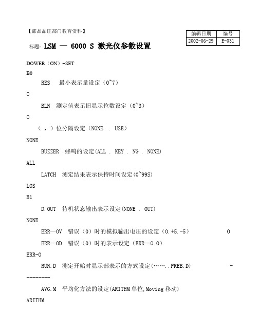
【部品品证部门教育资料】标题:LSM — 6000 S 激光仪参数设置DOWER (ON )+SETB0RES 最小表示量设定(0~7) OBLN 测定值表示旧显示位数设定(0~3) O( ,)位分隔设定(NONE . USE ) NONEBUZZER 蜂鸣的设定(ALL . KEY . NG . NONE) ALLLATCH 测定结果表示保持时间设定(0~99S) LOSB1D.OUT 待机状态输出表示设定(NONE . OUT) NONEERR —OV 错误(0)时的模拟输出电压的设定(0.+5.-5) OERR —OD 错误(0)时的表示设定(ERR —O.O ) ERR-ORUN.D 测定开始时显示部表示的方式设定(……..PREB.D) ---------AVG.M 平均化方法的设定(ARITHM 单位,Moving 移动)ARITHM 编辑日期 编号 2002-06-29 E-031JDG.M 合否判定方法的设定(LL—LH上下限,L1—L6段选别,NO—UL目标值与公差)COPY 目标值与基准值(4-8)设定(NONE . NO-REF) NONEB2WORK . D 测定机种别设定(OPA OUE 不透明,TRANS 透明) OPAQUEFINE 极细线测定有否设定(FINE . NONE)FINEPROG 同时测定的设定(SINGLE 单一,DUAL)DUALTYPE 二元测定的设定(→ W.DXY.DF.NONE)NONEDXY 演算设定﹛(X+Y).(X+Y)/2.(X-Y).(X-Y)/2﹜SEG 段节指定方法设定(SEGMENT.EDGE) SEGMENTB3ADE 异常值除外机能设定(E) NONEAWDT 作业自动检出机能设定(NONE.PIA直径检出方式.POSITN位置检出方式) NONESCAN 检出扫描回数设定(16回 , 1回) 16回GTJ 组别判定设定(E) NONEGTJ.D 组别判别定输出设定(NONE.OUT) NONEB4RS-232C RS-232C通道设定(COM.PRN.NONE) PRNBAUD RS-232C通信速度设定(9600,19200,1200) 2400,48009600LENGTH RS-232C语长设定(8,7) 8PARITY RS-232C同步设定(NONE,DDD奇数.EVEN偶数) NONEDELIMT RS-232C定义付设定(CR+LF,CR,LF) CR+LFCONTRL RS-232C制御方法设定(NONE3线式 ,USE)USEB5RUN I/O 模拟接O设定(S.RUN单行设定,T.RUN期间连续设定,C.RUN连续测定) S.RUNOFFS I/O模拟接O OFFS入力设定(OFFS补正,HDLD同步)OFFSGO I/O模拟接O GO入力设定(GO.STB.ACK) GOB6DCU DCU设定(NONE.DCUI.BOTH)。
光学计检定装置标准代码

光学计检定装置标准代码
计量标准代码计量标准名称01000000几何量
01191420手持式激光测距仪检定装置01200000线纹
01200011激光干涉仪工作基准装置01200012长光栅工作基准装置01200013长光栅位移传感器工作基准装置01200014长光栅测量系统工作基准装置01213300显微标尺标准器
01213500基线场检定装置
01213700基线尺检定装置
01213705光学机械比较仪标准装置01213711双频激光干涉仪标准装置01213712纳米光栅校准装置
01213730温度线膨胀系数检定装置01214100长光栅检定装置01214107长光栅线位移传感器标准装置01214109位移测量仪检定装置01214110引伸计检定装置
01214500线纹尺检定装置
01214501光电光波比长仪标准装置01214900线纹尺标准装置01214901激光干涉比长仪标准装置01214910一等线纹尺标准装置01214920二等线纹尺标准装置01214930三等线纹尺标准装置01214931一等金属线纹尺标准装置01214935二等金属线纹尺标准装置01214937三等金属线纹尺标准装置01214939三等金属线纹尺检定装置01214951一等玻璃线纹尺标准装置01214955二等玻璃线纹尺标准装置01214956短标尺标准装置
01215500钢卷尺标准装置
01215501π尺标准装置
01215600纤维细度测微尺标准装置01215900木(折)直尺检定装置01215901水平尺校准装置。
新帕泰克WINDOX 5 SUCELL 软件操作手册
严正说明对该文件和软件的拷贝,不管是整体拷贝还是部分拷贝,都是不允许的,除非经过了正式的书面授权。
德国新帕泰克公司(Sympatec GmbH)保留对软件和文件的所有拷贝的权利。
目录1. 概述___________________________________________________52. 软件操作_______________________________________________5 2.1. 预热和仪器启动_______________________________________________5 2.2. 软件应用_____________________________________________________62.2.1. 样品信息的输入(Product)____________________________________________62.2.2. 镜头的选择(Range)_________________________________________________62.2.3. 触发条件的设定(Trigger Condition)___________________________________72.2.4. 分散条件的设定(Disperser)___________________________________________82.2.5. 工作参数(Parameter)_______________________________________________122.2.6. 备注(Comment)___________________________________________________132.2.7. 测试 (Run)__________________________________________________________132.2.8. 结果输出(Out put)_________________________________________________152.2.9. 工具栏按键说明_____________________________________________________162.2.10. 菜单介绍__________________________________________________________173. 信号检测窗口(Signal test window)______________________18 3.1. 认识信号检测窗口____________________________________________183.2. 信号检测窗口的作用__________________________________________214. 报告和图形格式的修改(Template Edit)__________________22 4.1. 图形格式修改(Graph Configuration Edit)_______________________224.1.1. 增加特定数值_______________________________________________________224.1.2. 边界和显示调整_____________________________________________________26 4.2. 报告格式修改(Template Edit)_________________________________26 4.3. 报告电子文档导出(Report export)_____________________________295. 报告解释(Explanation of Nomenclature)_________________31 5.1. 参数定义依据_______________________________________________31 5.2.参数定义___________________________________________________325.3. Q3(x)和q3lg(x)的关系和计算方法______________________________32 5.4. SMD 和VMD的定义和计算方法_______________________________33 5.5. Sv 和Sm的定义和计算方法___________________________________35 5.6. 详解_______________________________________________________366. WINDOX数据库_______________________________________36 6.1. 数据库管理(Database Administration)__________________________366.1.1. 数据库的建立、注册和取消(Create, Register & unregistered)______________366.1.2. 数据库维护(Maintenance)___________________________________________416.1.3. 数据维护提醒信息___________________________________________________446.1.4. 数据备份(Back up)_________________________________________________456.1.5. 备份数据的重新启用_________________________________________________47 6.2. 数据转移(Database Explorer )_________________________________49 6.3. 数据库转换__________________________________________________50 6.4. 用户权限管理(User Administration)____________________________517. 请求服务(Service Request Report)______________________528. 服务机构______________________________________________571. 概述本手册详细介绍了如何来通过新帕泰克公司的标准WINDOX软件,来操作SUCELL系统。
3016中文说明书-(1)资料
Lighthouse Worldwide SolutionsHANDHELD 粒子计数器操作手册型号:3016,5016版本2.60 2011年版本Lighthouse国际有限公司1.介绍概要本操作指南描述了如何使用Lighthouse HANDHELD 3016和5016系列空气粒子计数器.这种型号数字代表了所测量的最小的粒径范围.数字“3016”表示在0.1CFM时最小的通道为0.3μm.数字“5016”表示在0.1CFM时最小通道为0.5μm.3016+和5016+型号的仪器可以达到六个粒子通道,两个环境传感器和一个彩色可触摸的界面.这种3016+和5016+型号的仪器也可以配置一个内置热敏打印机和一个标准可充电电池.(注意对于每一种HANDHELD类型的标准通道配置,可以查看这一章节的HANDHELD的参数表.)所有的HANDHELD系列仪器均包含一个微处理器来控制所有仪器的功能.数据以总量和分量模式显示为原始数据和对应每立方英尺或每立方米的粒子浓度.HANDHELD使用激光器二极管为激光光源并收集粒子反射光.粒子反射从激光管中发出来的光.这种可收集的光被收集并且集中在光电效应管上,它可以把光束转换成电子脉冲.这种脉冲可以计算并且可以根据它们的高度测量出粒子范围.结果以相应的粒径通道的粒子数显示出来.描述LIGHTHOUSE HANDHELD仪器使用最新的光学粒子检测技术.提供了当流量为0.1CFM(2.83升/分钟)时最小敏感度为0.3μm的3016/3016+产品线和最小敏感度为0.5μm 的5016/5016+产品线,HANDHELD系列提供一个最大可达25.0μm的动态粒径范围.集成了一个大的可触摸界面(3016+和5016+为彩色,3016和5016为黑白),HANDHELD系列仪器操作和设定极其简便.HANDHELD系列能存储大量数据,3016+和5016+的六个粒子计数通道和两个环境传感器的数据和3016和5016的两个粒子计数通道和两个环境传感器的数据.所有的数据能迅速且可靠的下载到计算机或者打印到它的打印机(3016和5016可选打印机,3016+和5016+内置打印机).HANDHELD系列的仪器允许你:设置采样和间隔时间设置单一位置的采样次数可外接两个环境传感器按联邦标准209E(ft3),209E(m3),EC GMP ,ISO 146441-1和英国标准5295打印报告保存历史数据使用所附送的数据转换软件打印图表或下载数据到EXCEL文件便于制图.2.打开检查和安装初始检查(注意:检查包裹外包装的震动标记;它是否为红色或者清楚?如果它为红色,表明它在运输过程中受到了震动.请确认它的功能和装置.)仪器在工厂中已完成检测和试验,并且准备签收.当收到货物时应检查包装箱是否有损坏.如果包装箱损坏,应立即通知承运商.如果包装箱损坏了,小心打开它并在使用前检测已打碎的部件,刮痕,凹陷及其它有损坏的部分.核实包装内容1.HANDHELD粒子计数器2.粒子计数器校准证书3.快速指南4.操作手册7.带胶管的0.1CFM流量0.2μm的零过滤器8.电源线9. 2个保险丝11.数据传送软件(LMS XChange)CD12.数据传送线及连接插头13. 2卷打印纸(3016+和5016+为标准配置,3016和5016为选件)如果对于上述所列有缺少,请立即与lighthouse 销售代表联系,免费电话800-945-5905.保留外包装及其它物件以便邮寄回去做仪器的年度校正.型号Lighthouse Handheld 3016最小粒直径0.3µM通道数 6标准通道0.3, 0.5, 0.7, 1.0, 2.0, 5.0µM, 流量控制0.1 CFM显示屏幕Touch Screen 1/4 VGA零顾虑器<1 / 5 minutes测量效率50%Light Source Laser Diode最大浓度@ 保证5%错误率2,000,000 Particles / Ft3 流量Internal真空泵Carbon Vane输出信号RS-232测试点0-999附件某些附件可以订货,装配仪器来满足你的要求.有些可以选择,而有些对每一个仪器是标准的.●温湿度探头(选件)------插在仪器的上部,4-20mA探头监测相对湿度(0%-100%)温度(-17.8℃-65.6℃或0-150)结果可以显示,打印,能够下载到LMS软件作为备份和历史数据查看.●标准等动力采样探头(标准件)-使用在计数和实际的粒子大小分布之间的最大关联单向气流.也可用于手持测量局部粒子计数.●过滤扫描探头(选件)-用于过滤装置的泄漏的扫描.●带轮运输箱(选件)●打印纸(对于3016+/5016+为两卷,对于3016/5016为选件)●净化间打印纸(选件,必须定购10卷或以上).●认证文件(选件)●锂电池,可移动和充电(对于3016+/5016+标准,而对于3016/5016为选件)●外置电池充电器(选件)●净化间手推车(选件)●USB串口适配器,为只有USB而无9针串行通信口的笔记本而备.●LMS软件,一种分析工具允许使用者:1.从仪器上下载数据2.保存数据作为历史数据查看3.可以打标准报告等等欲了解更详细的内容,请联系Lighthouse.安装连接电源电源输入为85-264V AC,47-63HZ.HANDHELD包括一个电源线.电源开关位于仪器的前部.推荐使用电源保护装置以防止开机时电压不足.当HANDHELD保持在固定位置时使用不间断的电源供应可以防止仪器的损坏或电源输出过程中的数据的丢失.安装电池HANDHELD3016+/5016+配有可充电的锂电池.这种可充电的电池对于3016/5016为选件.在仪器便携式使用操作前,应安装电池.开始电池可能未被冲满电.安装后应立即充电,把充电器插入AC电源并打开位于前部的电源开关.(警告:通过机器充电时,插入AC电源并打开位于前部的电源开关.)安装电池前,应确保电源开关处于关闭状态,然后遵循下列步骤;1.如图2-2,逆时针旋转锁扣打开电池舱后盖.图2-2电池箱盖4.按下连接器直到你听到咔嚓一声.5.如图2-5,下一步,把电池推入电池舱.6.将电池完全推入电池舱, 关闭舱门, 顺时针系紧螺丝, 锁住舱门.取出电池1.如图2-7,打开电池后舱盖并牵拉丝带以取出电池.2.如图2-8,当电池完全拽出后,抓住V型柄,松开电池电线,轻拽出并直到电线连线离开电池.图2-8松开连接线(警告:仪器运输前应卸掉电池.)连接一环境传感器:HANDHELD系列仪器在它的背板上有4类4-20mA的模拟输入口,针对这些口将在第三章做详细描述.可连接的模拟传感器为温度,相对湿度,风速,压差,静电,分子污染分析仪等等.每个传感器通过位于仪器后部的RJ—12连接口与HANDHELD连接.请查阅每一种传感器手册以得到正确的管脚图.连接外置电脑或设备管理系统.HANDHELD系列仪器具有连接到Lighthouse监测系统,LMS Express或LMS Xchange 数据转换软件以便下载数据.下载数据到Lighthouse监测系统(LMS)或LMS Express,你能存储历史数据,以便将来查看.在LMS Xchange,数据可以输出到a*.csv文件存储历史数据.在LMS Xchange软件和HANDHELD仪器之间有多达200个数值位置标号可以传输.这种转换通过Modbus通讯协议完成.请查阅LMS, LMS Express或LMS Xchange手册获取更多信息.3.操作这一章描述如何使用HANDHELD空气粒子计数器.这一章中的说明将以HANDHELD 3016+型号仪器的粒径通道和报告为准,除非特别说明.将HANDHELD仪器从箱子里取出,开始使用仪器,按如下步骤完成.1.把仪器放在你准备检测的地方.2.根据第二章指南装入电池.3.插上AC电源.4.从采样口处去除保护管,如果使用提供的标准等动力采样头,通过采样管连接到位于仪器顶部的入口处,装上等动力采样头.5.在前面板把电源开关置入ON位置.6.当通电后,仪器显示开始屏幕.7.显示MAIN(菜单)屏幕.8.如果准备用环境传感器,把它们插入到仪器的背板上.Lighthouse出售的一种4-20mA温/湿度棒可直接连到口1和3.温度数据在位置1或3显示,湿度数据将在位置2或4显示.9.在触摸屏上,按下START/STOP按钮开始启动仪器.10.当采样泵最初打开后,STARTING将显示.11.当计数开始,COUNTING将开始显示,测试结果根据每一粒子的大小显示出来.12.如果设置了采样间隔,在每一采样结束后显示HOLDING,当所有样本完成后显示FINISHED.13.如果在所有检测完成前你想停止,则按下STOP/STOP按钮.如果按下了STOP键,“STOPPED”字样将显示以表明采样是在未完成时停止的.(警告:a.不要试图用该仪器采样能起化学反应的几种气体,例如氢气和氧气.起反应的气体能给仪器带来爆炸的危险.)b.直接采样高压下的任何气体将会损坏仪器.c.如果所采气体与环境空气的密度不一样可能会导致结果不正确.注意:泵的马达需要5秒钟达到1CFM.“STARTING”时间包括这5秒钟的时间.警告:a.为了防止损坏仪器,水,溶剂和其他任何类型的液体都不能通过采样口进入仪器.b.采样管防尘帽盖在上面或堵住的时候不能开启仪器,否则会损伤内部泵.)触摸屏概要HANDHELD系列仪器集成了独特的可触摸屏来控制和设定仪器.增强型有(+)配有彩色触摸屏,基本型号采用单色触摸显示屏.此界面允许使用者方便地操作和应用,所有功能均可通过触摸屏来访问.*如果设置了开机密码**如果设置了配置密码主菜单主菜单提供了使用者对仪器功能状态的快速查看, 仪器可通过AC电源或内部可移动的电池来供电,(针对(+)号仪器;对基本型号为选件),电池显示将会显示电池的容量.图3-1主界面---电池供电图3-2主界面---市电供电AC显示符号显示从AC电源获得能量.LOCATION: 显示正在测量的区域.每台仪器可以设定多达200个区域标记.LOCATION选择按钮:允许用户在采样开始之前改变区域标记.LOCATION+/-按钮:当仪器开始计数时LOCA TION选择键和按钮变成+和-按钮.这?样允许用户在采样间隔内增减位置标记.ABOUT按钮:显示仪器版本号和仪器型号.ALARM ACKNOWLEDGE按钮:当任何通道粒子满足报警条件时,HANDHELD仪器会在采样过程中每秒产生鸣叫.按下Alarm Acknowledge按钮会让余下的采样时间内不产生鸣叫.如果仪器连接了外置的报警灯或蜂鸣器,按下Alarm Acknowledge按钮会在余下的采样时间内关闭报警灯或蜂鸣器.PRINT LAST RECORD:使用当前配置以当前的数据格式打印最后一个保存的数据(即是独立值对累加值,原始值对浓度值,立方英尺对立方米).打印设置是在PRINT SETUP 菜单下CONFIGURATION页面来完成的.更详细内容会在本章节的CONFIGURATION小节阐述.Date/Time:显示当前时间,日期.Battery indicator:显示仪器正在使用可充电电池电源,电池容量通过电池符号来显示,当电池耗损时,在屏幕上会显示“BATT LOW”字样.仪器会连续报警直到插入外接AC电源给予充电.(注意:如果在仪器的采样过程中电池指示标记出现“×”内部流量泵会自动停止以防止电池彻底放电.如果发生该情形,请外接市电并确保前面板上的电源开关是打开的.完全充满电需要4-5个小时.仪器在充电过程中你可以继续运行采样.)AC Indicator: 当插入AC电源时,AC显示会出现,表明仪器正由市电供电,此时如果接有电池将会给电池充电.Flow Status: 当仪器在采样时,流量状态指示会显示流量充足或不足.Service indicator:如果仪器需要被清洁或保养,Service显示开始.DA TA DISPLAY: 这将显示所测粒子是以独立值(Diff)或累加值(Cuml)显示,如果所测粒子显示是浓度值,将会表明是每立方英尺或每立方米.Analog Data:如果外接模拟传感器并且被激活了,该项将对前2个通道的数据提供一个快速浏览的方法.MODE:显示当前选择模式,可能的模式有AUTO自动,MANUAL手动, Concen浓度, BEEP报警两种模式.CYCLES:显示在自动模式下设定的采样次数的数量.如1/3表示这个计数是在为该区域要取样的3个样本中的第一个采样数据.最大周期次数为999.当设置为0时,仪器将按自动模式工作直至按下STOP按钮.SAMPLE TIME:时间(时:分:秒)是一次计数循环周期,当仪器处于自动或手动模式时,显示在主屏上的采样时间会递减,这样你就知道采样还剩多少时间.在浓度模式时,每个样本会计数到6秒.HOLD TIME: 显示二次周期之间的间隔时间,最大间隔时间为99小时59分59秒.(注意:如果间隔时间大于1分钟,在这段时间内泵会自动停止.在间隔时间快完时泵会自动开启.)RECS:显示储存在仪器中的采样记录的数量和可存储在仪器内的总数量.数据存储区是一个循环的缓冲器.当新数据存储在已满的区域时会在前面出现一个星号.+型号可以存储3000组数据,普通型号可以存储1500组数据.START/STOP:按下屏幕左下方的START按钮开始计数.当仪器工作时,在屏幕的右下角“REPORTS”按钮上面将会显示“COUNTING”字样.按下STOP按钮停止计数,“STOPPED”字样将会出现.图3-4计数模式(注意:从启动开始流量泵需要5秒钟的时间才能达到满负荷,在这段时间内“STARTING”字样将会出现.)Changing Locations当要为准备采样的样本更换区域标记时,你可以通过在屏幕上方按下LOCATION键来实现.这将显示一个界面让你选择一个新的区域标记.使用上下键来选择.单个的上下键会逐行移动.双键会显示上或下10个数据块.三键会跳到上或下的100个区域.这便于查找.图3-6箭头按下MAIN按钮将会回到主画面.当前选中的任何一个区域标记将会在主画面显示.图3-7新选中的区域标记Locations and AUTO Mode当仪器为自动模式时,START按钮被按下,仪器会根据已经设定的采样时间,间隔时间和循环周期等参数开始自动计数.当仪器显示为HOLDING时,你可以使用+和-按钮来改变数据存储的位置标记.例如:如果你想采样二个不同位置,二个位置之间需要步行5分钟.把你的间隔时间设为5分钟,在第一个周期从位置1采集数据,然而当仪器对第一周期结束计数时,在HOLDING5分钟内,调整到位置2,并移动仪器到第二个位置,你的仪器将位置1数据存为第一个记录,位置2数据存为第2个记录.图3-8使用+和-来改变区域标记当仪器结束COUNTING并进入HOLDING状态,数据将被保存到显示的位置处.区域标记名称可以用Configuration菜单下的Location编辑功能来实现.区域标记名称可以由8位的数字、字母和下划线构成.欲了解详细内容可以参见后面章节. Zoomed Data View在粒子数据显示的任何区域按压都会放大屏幕.如图3-9.图3-9放大数据显示在该页按压右边的工具条可以实现如下功能:开始/结束采样显示粒子/模拟数据显示累加/独立粒子数显示原始/浓度粒子数打印最后一组保存数据(只有仪器处于STOPPED和HOLDING状态时才能完成两种状态之间的切换.)当仪器在STOPPED和HOLDING状态时,在白的数据显示区域内按压任何一个地方都会返回到主画面.Data Setup: 包括设置粒径通道,模拟通道,样本存储参数,采样设置,报警使能和报警门槛以及清空缓存.Device Setup: 包括设置仪器的日期和时间,LCD对比度,仪器嗡鸣声响度,调整触摸屏,使能自启动,通信地址,区域标记名称,密码限制,打印设置和浏览仪器当前参数.Data Setup粒径通道可以在如图3-11页面进行设置.绿色的对号表示显示该通道.绿色的对号是切换键.按下一次不显示该通道,并且还出现一个红色的“×”以表明该通道被废止了.再次按下该键又会变成对号并使能该通道.按下MAIN或BACK将会提示清空所有存储的数据.(注意:当粒径通道被使能或废止时将会清空数据存储区,这样在存储区里的数据就会有相同的通道数.)图3-12清空数据界面如图3-12按下CANCEL键会取消设置并退回CONFIGURATION画面.当通道被废止后,它们将不会在主画面、报告、打印输出上出现.被废止的通道在数据存储区依然存在,但在这些通道将不会记录数据.模拟通道可以指定一个型号(4位)如图3-14和它的测量单位(4位)如图3-15.图3-14设定模拟型号图3-15设定模拟单位按下最小值键来输入数据下限,按下最大值键来输入数据上限.图3-16最大值、最小值设定界面当设备不在计数或处于两次采样中间的待机时段内,按压粒子数据显示区域的任何位置都会放大画面,然后如图3-18所示切换到显示模拟传感器数据的画面.图3-18放大的数据浏览区:模拟数据采样定时和采样样本数在如图3-19的页面进行设置.CYCLES:设置采样循环次数来定义在该位置仪器采样几次.这仅仅应用于自动模式里.可以设置0-999次.当采样次数设为零时,仪器会一直运行直到按下停止键.选择CYCLES按钮,用右边的数值键盘来输入采样次数,按下回车键完成设置.DELAY:初始延迟时间(时:分:秒)是按下启动键和泵实际开始运行之间的时间段.这给操作人员一定时间来离开将要进行测试的区域来确保测试是在受控的条件下进行的.最长延迟时间是99小时59分59秒.选择DELAY按钮用右边的数字键盘输入时分秒,按下回车键完成设置.HOLD:间隔时间(时:分:秒)是在采样之间的仪器待机时间.设定方法同采样时间一样.最长间隔时间是99小时59分59秒.这里是递减来显示待机时段还剩下多少时间.选择HOLD按钮用右边的数字键盘输入时分秒,按下回车键完成设置.(注意:如果在自动模式里将间隔时间设为0:00:00,仪器将会按照预设的采样时间和采样次数运行,但在采样之间不会待机.如果间隔时间大于1分钟,在待机时间内泵会停止运行.当泵在再次运行的时候,在采样开始之前它将需要5秒钟来达到1CFM的流量.)SAMPLE:采样时间(时:分:秒)是采样计数的时间段.当仪器处于自动模式和手动模式下采样,在主画面该时间递减,这样你就很直观地知道还剩多少时间.选择SAMPLE按钮用右边的数字键盘输入时分秒,按下回车键完成设置.VOLUME:除了直接设置采样时间外,你还可以通过设定立方英尺、立方米、升来确定样本量.当该项被设置后采样时间自动更新了.(注意:当以升来衡量采样体积大小时,最大可以取样的体积是9999.99升,相应的采样时间是05:53:08.当以立方英尺和立方米为量纲时,最大的采样时间是23:59:59分别对应1439.983立方英尺和40.776立方米.对于1cfm的仪器,如果最小采样体积是0.001立方米对应的采样时间是2秒.).按下BACK键回到CONFIGURATION画面或按下MAIN回到主画面图3-21计数模式COUNT MODE如下两种模式可选:自动、手动、鸣叫、浓度.AUTO------:当仪器在自动模式时,START按钮按下后,仪器根据采样时间,间隔时间及设置的循环次数自动计数.如果循环设为0,则仪器自动计数直至STOP按钮按下为止.MANUAL-------:当START钮按下后开始计数,在程序控制的采样时间段结束后停止.CONC(Concentration Mode)------:当仪器在Concentration模式下,它给出在一定空气量的粒子浓度值,并以每立方英尺或每立方米为单位显示在主界面上.当你按下START时开始计数,直到再次按下STOP结束.测量数值及显示每6图3-20改变采样体积单位秒更新一次.BEEP报警模式:在这种模式下,仪器根据设置值来报警.当你按下START钮计数开STOP钮结束.如果通道大小未选择,BEEP报警模式将自动选择最小的通道报警而不管是否设置该值.(小技巧:鸣叫模式可以用来检漏,报警门槛值设为1,模式设为BEEP模式.注意:BEEP模式只对累加值起作用.)PARTICLE DISPLAY仪器的数据可以以独立值DIFF和累加值CUML形式显示.对于lμm通道累加值,是该通道的总数加上2.5μm通道数据和5μm数据的总和.对于lμm通道独立值,是在lμm和2.5μm通道之间的粒子数.主页面的数据是根据选定的格式来显示的.数据格式可以是原始数据或标准浓度值.原始数据是粒子计数的实际数,Norm数据是根据选定的单位立方英尺或立方米而从原始数据计算出来的粒子浓度.空气容积=采样时间(分)×流量速率(cfm)标准数据=粒子数/空气容积按下BACK键回到CONFIGURATION画面或按下MAIN回到主画面..Alarm Threshold按通道序号后面的门槛值可以设置对应通道的报警门槛.如图3-23.图3-23设定报警门槛值要清仪器的数据存储区按清除按钮.如图3-27所示按OK键清空所有数据,按Cancel键退出该屏而不清数据.图3-27 清数据存储器界面DEVICE SETUP仪器的日期和时间在如图3-28的界面设置.图3-28日期和时间设置界面日期的设置通过输入月,日,年后按回车键完成.日期的显示可以以月份排在最前面.这是缺省设置.日期的显示也可以以日排在最前面.图3-29日期选项:日排第一位日期的显示也可以以年份排在最前面.图3-30日期选项:年排第一位时间的设置按TIME键.图3-31设定时间时间的设置通过输入小时,分,秒后按回车键完成.按下BACK键回到CONFIGURATION画面或按下MAIN回到主画面.(警告:请仅按指定的位置.如果在该过程中按别处,将会错误地调整它.)·如图3-33屏幕出现.图3-33屏幕调整步骤1·按位于左下角的圆圈.(注意:使用PDA输入笔将使屏幕界面调整更精确.)·然后按位于与右上角的圆圈.图3-34屏幕调整步骤2·在校正屏,按压屏幕上几个不同位置.你所触摸的每一个位置有“X”显示表明这种调整成功.图3-35验证触摸屏阵列·按屏幕中心上矩形中的任一位置来完成调整.·调整完成后关闭电源开关.等几秒以后再打开电源.Alignment At Startup你也可以通过先关闭电源然后用一根手按住触摸屏再打开仪器来访问屏幕调整界面.这将显示如图3-36所示界面.图3-36在开机时调整(注意:如果在仪器的正常使用过程中按压工具条没反应或不起作用,关掉仪器,然后在屏幕变成空白以后再打开.)·如前面所描述过程继续.·当调整完成后,关闭电源再开机.当仪器连接到数据采样系统或串接到其它RS-485仪器上时,通信地址是用来识别仪器的.LMS Xchange和LMS Express RT/RT+软件将会在你指定的通信地址上寻找仪器.范围是01—63.对于RS-485通信,多通道串接链上的每一个设备都必须有一个唯一的地址.图3-37通信地址设置界面用内置的数字键盘输入相应的通信地址,再按回车键.按下BACK键回到CONFIGURATION画面或按下MAIN回到主画面.你可以设置数字字母标识的200个不同的区域标记.在如图3-38所示的区域标记设置页面,用上下键选择你要改变的名称.图3-38区域标记选择界面按下EDIT键会出现如图3-39的界面.图3-39区域标记编辑界面用数字字母键盘和下划线来输入新的区域标记的名称.如果输错了,用ERASE键删除输入的最后一个字母.输入回车键.用箭头来选取你想编辑的下一个区域标记再按编辑键.如此方法可以编辑任意你想要改变的区域标记名称.按下BACK键回到CONFIGURATION画面或按下MAIN回到主画面.该仪器可设置两级不同的密码权限.设置开机密码,选择POWER ON工具条,然后用数字键盘输入密码.如果输错了按清除.按回车键保存.设置系统设置密码,选择CFG工具条,然后用数字键盘输入密码.如果输错了按清除.按回车键保存.按下红色的“×”号来使能任意一个或两个密码设置功能.按下BACK键回到CONFIGURATION画面或按下MAIN回到主画面.POWER ON PASSWORD如果设置了开机密码,在开机时要求输入密码.当你开机以后会看到如图3-41所示界面.图3-41开机密码访问界面仪器将被一直锁住直到你输入了正确的密码.(警告:请把你的密码保存在一个安全的位置.如果忘记了请致电Lighthouse技术支持寻求帮助.)CONFIGURATION PASSWORD系统设置密码防止未被授权的访问.图3-40密码设置界面图3-42仪器配置密码访问界面在主界面按DATA键将会浏览数据存储器.依据采样设置,数据将会以原始数据或对应ft^3或m^3的标准浓度值显示.(注意:利用右侧的上下键翻页查阅数据.单键一次滚动一个记录.双键一次移动10个数据.三键一次移动100个数据.当数据存储器的数据发生了覆盖,第一个显示的数据是数据存储器的第一个记录但并不是第一个测试点的值.如果正显示第一个记录,你按下键一次,它翻到最后一个记录.)图3-49浏览数据界面---原始数据图3-50浏览数据界面---标准浓度值(ft³)。
QA文件目录
30 流程图的编制标准操作规程
31 批记录管理标准操作规程
32 原始记录管理标准操作规程
33 用户需求(URS)编写及管理标准操作规程
34 状态标识管理标准操作规程 35 质量部门印章管理标准操作规程
36 质量档案管理标准操作规程
37 计算机化系统电子数据管理标准操作规程
38 标准操作规程制定标准操作规程 39 内部图纸管理标准操作规程
质量评审与审计(2) 133 GMP自检标准操作规程 134 外部审计
目录
责任人 批准日期 生效日期
备注
培训
找培训记录 找培训记录 找培训记录
MiNi Capt 100M压缩空气浮游菌采样器使用、清洁、维护标准操作规 118 程
投诉与不良反应类(11) 122 用户投诉处理程序 123 药品不良反应监测报告管理规程 124 严重不良反应(包括死亡)、群体性不良反应应急处理标准操作规程 125 药品定期安全性更新报告管理规程 126 不良反应在线填报管理规程 127 个例药品不良反应处理管理规程 128 群体性药品不良反应处理管理规程 129 药品重点监测制度管理规程 130 不良反应信息管理规程 131 不良反应、投诉专线电话接听程序 132 疫苗临床试验严重不良事件报告管理规程
物料及产品类(21) 55 物料供应商管理标准操作规程 56 物料、成品代码制定标准操作规程 57 鸡胚供应商管理标准操作规程
质量保证部文件目录
文件编号 版本号
58 供应商投诉标准操作规程 59 菌毒种管理标准操作规程 60 菌毒种库管理规程 61 生产用细胞库管理标准操作规程 62 菌毒种、细胞管理小组职责 63 物料放行标准操作规程 64 物料紧急放行标准操作规程 65 不合格品处理标准操作规程 66 产品批号、生产日期、有效期制定标准操作规程
根据《医疗器械监督管理条例》及《医疗器械检测机构资格认可办法 (1)
全部参数
电子口腔镜YZB/苏0206-2003
39
一次性使用清洗器
全部参数
一次性使用清洗器YZB/苏0171-2008
40
拔牙钳
全部参数
拔牙钳通用技术条件YY/T0453-2003
41
无菌
全部参数
中华人民共和国药典2005年版二部附录Ⅺ H 医用输液、输血、注射器具检验方法 第2部分:生物学试验方法GB/ 一次性使用医疗用品卫生标准GB15980-1995
全部参数
中华人民共和国药典2005年版二部附录Ⅺ E 医疗器械生物学评价 第11部分: 全身毒性试验GB/ 医用输液、输血、注射器具检验方法 第2部分:生物学试验方法GB/
46
一次性使用管型痔吻合器
全部参数
一次性使用管型痔吻合器YZB/苏0521-2008
47
眼刺激
全部参数
医疗器械生物学评价 第10部分:刺激与迟发型超敏反应试验GB/ 医用有机硅材料生物学评价试验方法GB/T16175-2008
20
医用电气设备
全部参数
工业、科学和医疗(ISM)射频设备 电磁骚扰特性的限值和测量方法GB4824-2004
21
医用电气设备
全部参数
信息技术设备的无线电骚扰限值和测量方法GB9254-2008
22
电热手术刀
全部参数
电热手术刀YZB/苏0169-2002
23
手术刀片
全部参数
手术刀片YY0174-2005
全部参数
单道和多道心电图机YY1139-2000
94
新生儿心电图机
全部参数
新生儿心电图机YZB/苏0598-2009
95
- 1、下载文档前请自行甄别文档内容的完整性,平台不提供额外的编辑、内容补充、找答案等附加服务。
- 2、"仅部分预览"的文档,不可在线预览部分如存在完整性等问题,可反馈申请退款(可完整预览的文档不适用该条件!)。
- 3、如文档侵犯您的权益,请联系客服反馈,我们会尽快为您处理(人工客服工作时间:9:00-18:30)。
……………………………………………………………最新资料推荐………………………………………………… 1 序号 要求内容 响应内容 URS01 金属不锈钢外壳及采样头,定期进行清洁/维护/保养 满足:多款产品外壳及等动力采样头均为不锈钢材质,便于日常清洁、维护和保养。 URS02 无菌室尘埃粒子的监测 满足:产品适用于无菌室尘埃粒子的监测
URS03 工作环境:温度 10~35℃;湿度 ≤75 %RH 满足:工作环境:温度 0~40℃;湿度 10~90 %RH URS04 便携式 满足:便携式
URS05 易清洁,各连接部位平滑、圆角 满足:多款产品外壳及等动力采样头均为不锈钢材质,仪器连接部位平滑、圆整,便于日常清洁、维护和保养。
URS06 外表面材质不产生脱落物,不对洁净区造成污染,可接受消毒液擦拭,臭氧灭菌, VHP灭菌,甲醛熏蒸;采样空气环路可灭菌 满足:外壳采用316L不锈钢材质,不产生脱落物,不对洁净区造成污染,可接受消毒液擦拭,臭氧灭菌, VHP灭菌,甲醛熏蒸;采样空气环路可灭菌
URS07 外表面无明显的凸台和凹陷,不可避免时必须圆角、平滑处理,采样头采用等动力不锈钢采样头,耐灭菌。 满足:外表面无明显的凸台和凹陷,不可避免时必须圆角、平滑处理,采样头采用等动力不锈钢采样头,耐灭菌。
URS08 至少包括0.5/5.0μm,粒径0.5μm时计数效率100%,并有验证文件支持 满足:提供第三方权威检测报告 URS1流量: 100升/分钟 满足:需方可选择100L/min,误差满足GMP要求 URS1真空系统:漩涡式风机或真空泵 满足: 100L/min采用进口风机,
URS1计数频率:多数灵敏度极限值时为50%±10%(超过JIS标准) 满足:灵敏度极限值时为50%,满足JIS标准。
URS1零点计数:满足JIS标准 满足:零点计数满足JIS标准 URS1数据存储:可存储1000套完整的样本参数 满足:数据存储达到20000组完整的样本参数 URS1通讯模式:以太网、RS-232或RS-485;USB数据下载。满足:根据客户需要设计数据输出方式,RS232,RS485,USB数据……………………………………………………………最新资料推荐………………………………………………… 2 序号 要求内容 响应内容 其中USB接口可下载Excel及其它格式,方便客户直接电子文件。 下载等,其中USB接口可下载Excel等格式,方便客户直接电子文件。
URS1符合中国GMP标准的洁净室认证报告;平均值报告 满足:符合中国GMP标准的洁净室认证报告;平均值报告,最大值报告及置信度报告 URS1内置非热敏打印机,随机带5卷打印纸 满足:内置非热敏打印机,随机带5卷打印纸。
URS1外壳:符合GMP要求,耐甲醛和VHP灭菌要求 满足:外壳不锈钢材质,符合GMP要求,耐甲醛和VHP灭菌要求
URS1样本输出:内部过滤,符合HEPA标准(0.3微米>99.97%),不会破坏周边层流 满足:采样气体输出经过符合HEPA标准(0.3微米>99.97%)的内置过滤器过滤,而且排气口方向向下,不会破坏周边层流 URS2提供等动力采样头与主机的连接管件 满足:提供等动力采样头与主机的连接管件。
URS2提供3Q认证文件及服务,和计量检定机构授权的计量检定证书 满足:提供3Q认证文件及服务,提供第三方权威检测报告
URS2整机质保1年,激光源质保3年 满足:整机质保1年,激光源质保3年 URS2提供校准原始数据 满足:可以提供
URS2电池和电源:100-240伏,50-60赫兹;可拆卸可充电锂电池 满足:可充电锂电池。
2. 项目实施的用户需求 具有相应的资质证明及成功经验的设备供应商。 3.1 项目进度表
序号 要求内容 响应内容 URS25项目质量计划 满足:提供ISO9000证书 ……………………………………………………………最新资料推荐………………………………………………… 3 序号 要求内容 响应内容 URS26供应商具有生产此类设备的资质。 满足:提供营业执照等证明
URS27供应商的合同履约能力。供应商成本分析。 满足:提供部分已执行的履约合同,提供成本分析表格
3.2 法律、标准等常规要求 药品生产质量管理规范(2010年修订)及 附录1 无菌药品 药典:中国药典 (2010) GB2894—996安全标志
3. 环保健康安全(EHS)要求 4. 供货、服务要求 5.1 文件技术资料要求 提供设备的安装、运行和维护SOP,并且形成容易理解的文件,符合GMP的有关要求,本设备的供应商要对此进行初步审核,按合约要求把最终的文件连同货物一起传输过来,并把它作为付款的一个前提条件。 项目进行期间和完成之后,乙方必须交付给甲方3份所要求的文档:一份原件和二份复印件,此外,项目完成后将所有文档写入一张光盘交付甲方。 这一章所陈述的是最低要求。 序号 项目 备注 1 工厂运行测试。 2 现场验收方案(SAT)。 3 安装确认方案(IQ)。 4 运行确认方案(OQ)。 5 性能确认方案(PQ)。 ……………………………………………………………最新资料推荐………………………………………………… 4 6 设备清洁规程。 7 设备标准操作规程。 8 设备维护、保养规程。 9 装箱清单。 10 制造商资格证明。 11 质量及售后服务承诺。 12 产品合格证。 13 外购件合格证。 14 设备使用说明书。 15 材料清单及材质报告。 16 备品备件清单。 17 零部件清单(包括外购件的规格型号、使用说明书、制造商及联系方式)。 18 验证文件
5.2 制造测试 5.2.1 现场测试
序号 要求内容 响应内容 URS28 安装完成后进行现场验收测试SAT。 满足:安装完成后根据需方要求进行现场验收测试SAT。 5.2.2 安装确认(IQ)/运行确认(OQ) 序号 要求内容 响应内容
URS29 在设备完全交付使用前,应完成下列验证: IQ、OQ 。 满足:在设备完全交付使用时,配合需方完成下列验证: IQ、OQ 。
5.3 交货 ……………………………………………………………最新资料推荐………………………………………………… 5 5.3.1 设备包装、发运、运输、检查、存储、开箱 序号 要求内容 响应内容
URS30 由供应商负责按国家相关标准进行货物包装,货物包装须符合相应标准,该包装应适于长途运输,具有良好的防潮、防水、防锈、防野蛮装卸等保护措施,以确保货物安全运抵现场,供货商应承担由于包装、运输不妥引起的货物锈蚀、损伤和丢失的责任。
满足:供方负责按国家相关标准进行货物包装,货物包装须符合相应标准,该包装应适于长途运输,具有良好的防潮、防水、防锈、防野蛮装卸等保护措施,以确保货物安全运抵现场,并承担由于包装、运输不妥引起的货物锈蚀、损伤和丢失的责任。 5.3.2 设备安装和验收 序号 要求内容 响应内容
URS31 为项目的顺利完成和做好施工现场的安全管理工作在启动订单和安装设备之前,设备供应商应提供一份工作计划。要列明从开始交货到竣工验收结合的整个项目期间,采购方应提供的配合措施。以便于需方做好相关准备工作。 满足:公司对应每个项目有施工手册,仔细详列了整个项目的总过程 及供需双方承担的责任义务。
URS32 为便于管理中标人和采购人在项目期间的联络,应通过指定的双方全权代表进行。 采购方在设备制造过程中可随时对设备制造进度进行了解,设备供应方应予以配合。 满足:满足用户要求,配有明确的项目负责人。
URS33 由制造商承担设备组装、调整、测试和协助验证工作,制造商必须在投标文件中明确设备安装、调试的周期及交验时间。 满足:供方承担设备组装、调整、测试和协助验证工作,供方在投标文件中明确设备安装、调试的周期及交验时间。
URS34 供应商负责项目安装调试验收合格前货物的保险(并承担其服务人员服务现场的人身意外责任)。 满足:供方负责项目安装调试验收合格前货物的保险,并承担其服务人员服务现场的人身意外责任。
URS35 在制造商工厂进行预验收,预验收期间买方要对设备是否满足技术要求进行确认,并提出整改项目,预验收整改项目完成后,买方签字验收后设备才能进行包装和发运。 满足:需方到制造商工厂进行工厂现场验收,预验收期间需方可对设备是否满足技术要求进行确认,并提出整改项目,预验收整改项目完成后,需方签字验收后设备进行包装和发运。 ……………………………………………………………最新资料推荐………………………………………………… 6 序号 要求内容 响应内容 URS36 1、终验收在买方工厂进行,卖方负责在买方现场安装、调试设备,并对操作、维修等人员进行技术培训。 2、卖方负责协助买方进行相关验证活动,并对验证中出现的问题提出对策和解决方案,具体内容和要求见协议条款。 3、只有在安装确认(IQ)、运行确认(OQ)通过后才认为终验收合格。 满足:供方负责整个系统的设计、安装、调试以及对需方人员的培训,并协助需方进行相关验证活动,并对验证中出现的问题提出对策和解决方案。在安装确认(IQ)、运行确认(OQ)通过后终验收合格。
5.4 培训要求 序号 要求内容 响应内容
URS37 设备供应商负责所有技术指导和人员培训,包括:图纸、工艺、操作、设备维护、设备性能及问题解答等。 满足:供方负责所有技术指导和人员培训,包括:图纸、工艺、操作、设备维护、设备性能及问题解答等。
URS38 培训对象:管理、技术、维修、操作及相关人员 培训内容:综合培训(掌握设备理论知识) 现场培训(设备实践操作知识) 满足:根据需要放要求,对管理、技术、维修、操作及相关人员进行培训,内容为综合培训(掌握设备理论知识)及现场培训(设备实践操作知识) 5.5 质量保证和售后服务
序号 要求内容 响应内容
URS39 设备保修期自终验收合格后算起12个月,控制系统保修期自终验收合格后算起12个月。 满足:按合同要求
URS40 保修期内,卖方免费为买方维修设备(包括零部件费用);保修期外,长期提供优惠的维修服务及零部件,维修响应时间24小时。 满足:按合同要求 URS41 提供可满足两年设备运行需要的易损零部件及零部件及清单(包括报价)。 满足:按用户要求 5.6 要求和时间规定 序号 要求内容 响应内容