陕鼓A80-11轴流压缩机说明书
炼铁厂南区动力车间AV80.
炼铁厂南区动力车间AV80-16轴流压缩机工程设备和管道安装施工方案第一章:工程概况1.1工程名称:炼铁厂南区动力车间AV80-16轴流压缩机工程1.2生产、设计、监理单位1.2.1建设单位:炼铁厂南区动力车间。
1.2.2设计单位:1.2.3监理单位:1.3工程内容:炼铁厂为适应3200m³高炉生产的需要,将南区动力车间原汽拖鼓风机拆除,在原位置上安装一套用电动机拖动的轴流压缩机组。
轴流压缩机是为高炉提供风源的设备,是高炉的重要设备。
本机组为AV80-16压缩机组。
由陕鼓集团引进瑞士苏尔集团的技术,自行设计、制造的,具有流量调节范围和效率高等特点,它主要由轴流压缩机和电机及变速箱等设备组成,同时包括润滑油站及管道、动力液压站及管道、进、出风管道冷却水管道等。
其中轴流压缩机重量为98.5吨,电机重量为58吨,变速箱重量10吨,润滑站2吨,动力液压站1吨、润滑管道及进、出风等各种管道重量为80吨,总重量约249.5吨。
1.4本工程采用的规范标准1.4.1《AV80-16轴流压缩机安装使用说明书》和安装图—-- 西安陕鼓动力股份有限公司。
1.4.2《膜片联轴器安装说明书》和《电机安装说明书》以及《变速箱安装说明书》。
1.4.3《机械设备安装工程施工及验收规范》GB50231—981.4.4《冶金机械液压、润滑和气动设备工程安装验收规范》GB50387-20061.4.5 《现场设备、工艺管道焊接安装工程施工及验收规范》GB50236—981.4.6《压缩机、风机、泵安装工程施工及验收规范》GB50275—98第二章:施工部署2.1项目进度目标:严格按照生产方提出的开工和完工日期内完成安装工程,保证绝对工期。
2.2施工管理机构及施工人员安排:项目总负责人公司经理项目经理公司副经理1名施工管理员1人技术质量管理员1人安全管理员1人材料员1人资料员1人施工人员30人2.3项目管理目标:各机械设备安装符合国家验收标准及图纸设计要求,确保单位工程质量合格率达到100%,质量优良率达到85%主体工程质量达到优良。
空气压缩机操作指导书

3-1 下班后将开关关掉即可。
1.停机后放净气罐的油、水与压缩空气。
2.开机和关机时,注意有没有异常声响。
3.检查机器运行时是否出现异常的温度过高现象。
4.压缩机润滑油不足时一定要停机才能加油。
备注:
编制:审核:核准:版本:
XX有限公司
空气压缩机操作指导书
机器名称:空气压缩机机型:
项次
操3
开机前
操作方法
停止机器运行
1-1 检查润滑油的油位。
1-2 检查三角皮带的松紧度。
2-1 打开电源开关。
2-2 检查电机运转方向是否与护罩上所示转向箭头指向是否一致。
2-3 将压力自动开关调至所需的范围内。
压缩机产品说明书

5)顺序充气控制阀
压缩机送气进入顺序充气控制系统后,首先当压缩机排出天然气压力达到设定值,就优先打开高压顺序阀对高压瓶组进行充 气,管路中的单向阀使高压气体不倒流,其次是达到中压瓶组压力设定值时,打开中压顺序控制阀对中压瓶组进行充气,管路 中的单向阀使中压气体不倒流,压缩机继续排出天然气,直到两个瓶组充满为止。
5、仪表操纵系统
图5—5 仪表板部件 压缩机的操纵都集中在仪表板部件(如图5-5),操纵柜面板上安装有一、二级排气压力表、吸气压力表、油压表、高压气瓶 表、中压气瓶表、回收罐压力表、控制气瓶压力表。其下有对应的各种标牌,便于检查和操作。
对于因不遵守安全条列或是忽略了安装使用操作和维修的常规条列而造成压缩机损坏及其一切后果,本公司不承担任何责任。 二、压缩机主要技术参数表3--1:
该机主要用作加气子站用天然气压缩机,进入压缩机的气体必须符合下列要求: 1、应不含游离水; 2、硫化氢含量应小于20mg/㎡; 3、低热值不小于34MJ/㎡ 4、含尘量不大于5mg/㎡,颗粒直径小于10um; 5、总硫(以硫计)含量小于200mg/㎡; 6、二氧化碳含量小于3.0%(V/V)。 在本使用说明书中,我们详细介绍了该压缩机的操作使用、维护、保养等的方法,并对压缩机的结构等其他方面进行了必要的 说明。压缩机的安装、操作、维修应该严格遵守使用说明书的规定,对由于不适当的操作、维修或者不使用原配件等违反使用 说明书规定而造成机器的损坏及其一切后果,我公司不承担任何责任。 三、压缩机组的配置 该机组主要由降噪箱体、压缩机底架、压缩机主机、电动机、分离器、润滑油路系统、气管路系统、冷却器系统、仪表操纵系 统、辅 助及自动控制系统等组成。 四、压缩机主机简介(略) 五、压缩机系统简介 本压缩机有七个主要的系统:气路系统、冷却系统、排污系统、润滑系统、仪表操纵系统、控制管路系统及电器设备系统。下 面分别加以说明: 1、气路系统 气路系统的作用,主要是将天然气引向压缩机,经压缩机各级压缩,冷却、分离之后,再引向使用场所。 天然气从槽车通过卸气柱进入压缩机,压缩机在进口处配有二路直充管路,一路直充连接售气机低压接口,一路直充连接中压 储气瓶组,每路配有高压气阀。当进来气压力高时,打开二路球阀,可以不通过压缩机而用直充管路为售气机低压接口补气, 同时直接为中压储气瓶组补气。当进气压力与中压储气瓶组压力平衡时关闭该路的高压球阀。为售气机低压接口补气的直充管 路球阀可以不用关闭。 进压缩机的一路天然气依次进入进气分离器,一级气缸、一级冷却器、一级分离器、二级气缸、二级冷却器、二级分离器、前 置过滤器、除油过滤器,最后通过优先顺序控制阀将压缩天然气输送到中、高压储气瓶组(见图5-1)其中与以上部件连接的 管道等设备组成压缩机的气体主管路,安全阀排口管路、排除油、水用的排污管路以及连接压力表的管路等组成辅助管路。 注:进气过滤器需在机组运行200h后进行定期清洗或去除滤芯。 1)安全阀 安全阀是一种保护性装置,当系统中的压力超过工作压力时,本机安全阀就自动开启,把多余气体排掉,以使系统降低到正常 工作压力。本机安全阀安装在排气系统上,安全阀的开启压力如下(表压):安全阀开启压力:26.0~27.0MPa 本机安全阀是弹簧封闭式安全阀。它主要有阀体、阀瓣、弹簧座、弹簧、调节螺帽等组成。如需调整开启压力时,只需将安全 阀顶部的调节螺帽旋入活旋出即可调到所需要的开启压力。 由于本压缩机是压缩天然气的,所以安全阀打开后所放出来的天然气,用户必须用钢管引至安全位置排空。 备注:安全阀应按有关规定一年效验一次。 2)油水分离器
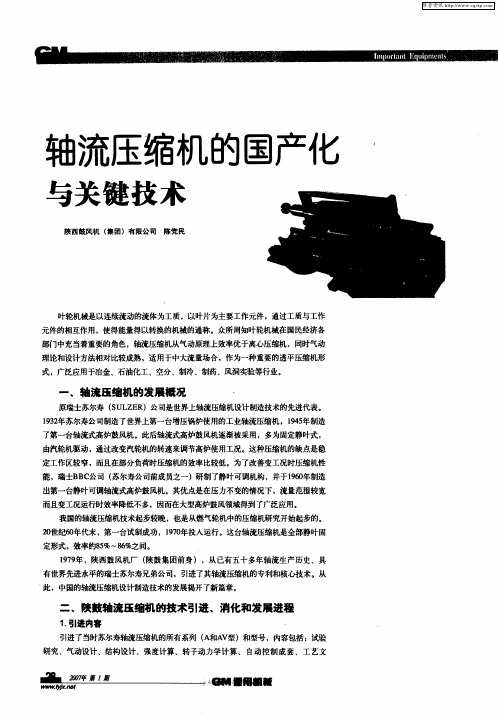
轴流压缩机的国产化与关键技术
A 6一 l 指轮毂直径为6c V3 4 3m,级数为l的全静叶可调轴流压缩机 。 4 A 3 l 指轮毂直径为6c 6一 4 3m,级数为l的静叶固定轴流压缩机。 4
中所产生的种种物理现象 ,但试验设
2引进技术的消化吸收与国产化进程中的关键产吕 .
在引进技术初期 ,陕鼓先后派 出10 2 多人次 ,28 0 0 工作 日在瑞士进行专 业培训 ,苏尔寿 公司也先后派 出4 多人次专家来华进行技术交流 ,现场培训 O 指导 。经过陕鼓广大技 术人 员积极地 消化 吸收 引进资料 ,刻 苦攻关 ,终于 在18 年 自主独立地为荆门炼油厂 。 O ,重油催化裂化装 置”设计制造 了 96 6 万t a
维普资讯
轴流压缩机的国产化
与关键技术
陕西鼓风机 ( 团)有 限公司 集 陈党民
叶轮机械是以连续流动的流体为工质 ,以叶片为主要工作元件,通过工质与工作 元件的相互作用,使得能量得以转换的机械的通称。众所周知叶轮机械在 国民经济各
部门中充当着重要的角色 , 轴流压缩机从气动原理上效率优于离心压缩机 ,同时气动
机 。型号分别有 :4 、4 、5 、5 、6 、7 、8 、9 、10 1 、15 4 。 0 5 O 6 3 l O 0 0 、12 2 、10
型号 命名 举例 如下 :
风机中。
第二类是 以叶栅风洞 中的平面 吹风 试验数据 为基础 ,称 为平面 叶 栅 法。这种 方法是假定静 止平面 叶 栅的性能与相应旋转的环型叶栅性能
A 4一 l主风 机 。 V5 2
备简单,在设计工况下用此方法所得
结果与实物试验结果接近 ,并且能在 短时间内设计 出各种不同参数的压缩 机 ,因而这种方法是计算轴流压缩机 的基本方法。 第三类是 以模型级 的试验数 据 为基础,称为模型级法。这种方法能 考虑单独级中的一切实际影响因素。 但模型级的原始设计也是应用平面叶 栅法。这种方法的缺点是试验设备较
气体压缩机说明书

en Installation instructions1234265626enSafe installationFollow these safety instructions when installing the appliance.¡Read this instruction manual carefully.¡The images shown in these instructions are for guidance only.¡The appliance can only be used safely if it is cor-rectly installed according to the safety instructions.The installer is responsible for ensuring that the appliance works perfectly at its installation loca-tion.WARNING ‒ Risk of explosion!Escaping gas may cause an explosion.▶All Installation, connection, regulating and conver-sion work to a different gas type must be carried out by an authorised professional while taking into account the respective applicable regulations and legal requirements as well as the regulations re-garding the local electricity and gas suppliers.Special attention must be paid to the provisions and guidelines that are applicable for the ventila-tion. For conversion work to a different gas type,we recommend that you call the after-sales ser-vice.¡Ensure that the kitchen is sufficiently ventilated, in particular when operating the gas cooking appli-ance.¡Do not connect the appliance to an exhaust gas system for combustion products.¡Never install the appliance in boats or in vehicles.¡The warranty applies only when using the appli-ance as intended.¡Before installing the appliance, check that the local conditions of the supplier are compatible with the appliance settings specified on the rating plate (type of gas and pressure, power, voltage).¡Secure the power cord to the cabinet to prevent it from touching hot parts of the oven or hob.¡Before any work is carried out on the appliance,switch off the power supply and the gas supply.¡Connect the appliance to the power supply using the earth.¡Do not make any changes to the inside of the ap-pliance. If required, contact our technical cus-tomer service.Before installing¡This appliance is a class 3 appliance in accord-ance with the EN 30-1-1 standard for gas appli-ances: Built-in appliance.¡This appliance can be combined with other hobs of the same brand by using the connection ac-cessory. See catalogue.¡The unit in which the appliance is installed must be stable and secured appropriately.¡The units in the vicinity of the appliance, the lamin-ated panels and the adhesive with which they are secured must be made of non-flammable, heat-resistant materials.¡Do not install this appliance above refrigerators,washing machines, dishwashers or similar.¡The appliance must only be installed on an oven with forced ventilation. Check the dimensions of the oven in the installation instructions for the oven.¡If you install an oven underneath the hob, the work surface thickness may differ from the dimensions given in these instructions. Take note of the in-formation in the oven installation instructions.¡If you install an exhaust air fan or an extractorhood, refer to the installation instructions for these.Always observe the minimum vertical distance to the hob.→ Fig. 1Preparing the units¡Make a cut-out in the worktop with the required di-mensions.¡In recesses of 500 mm, the appliance must be in-stalled on the front edge of the recess. → "Posi-tioning the appliance", Page 7→ Fig. 2¡Seal the cut surfaces of wooden work surfaces with a special glue seal to protect them from mois-ture.¡If there is no built-in oven underneath the hob, in-sert a non-flammable separator (e.g. metal or ply-wood) at a distance of 10 mm from the hob. This prevents access to the underside of the hob. The distance from the intermediate floor to the mains connection for the appliance must be at least 10mm.→ Fig. 3, → Fig. 47Positioning the applianceNote: Do not remove the adhesive seal fitted on the lower edge of the hob. The adhesive seal prevents the penetration of liquids.Do not use silicone to bond the appliance to the worktop.1.Position the hob with the upper side facing down on a flat, stable surface.2.Loosen the screws on the brackets so they can turn freely. You do not need to fully undo the screws on the brackets.→ Fig. 53.Turn the hob around and insert it into the recess.Insert the hob in the front of the recess.→ Fig. 64.Turn the brackets and tighten them fully.→ Fig. 7The position of the brackets depends on the work-top thickness.Removing the appliance1.Disconnect the appliance from the electricity andgas connections.2.Unscrew the brackets and proceed in reverse or-der.Connecting the gasObserve the country-specific guidelines.CAUTION ‒ Risk of explosion!A gas leakage may cause an explosion.▶If any connection is handled, check the seal.¡Arrange the gas connection so that the shut-off valve is accessible.¡Ensure that the information on the rating plate re-garding the gas type and gas pressure complies with the local connection conditions.¡Connect the appliance to a fixed gas pipe or a flexible metal pipe.¡The flexible metal pipe must not come into contact with the moving parts of the unit in which the ap-pliance is installed (e.g. a drawer) and must not be routed through any spaces which might be-come obstructed.¡Gas connection on the appliance: G 1/2.Spare parts for gas connectionYou can obtain the gas connection parts from the technical customer service.Pipe10008834Pipe for horizontal connection10003285Gas connection G 1/2▶Insert the seal between the gas connection of the appliance and the gas supply.→ Fig. 8LPG rubber hose connection1.Secure the sealing ring and the pipe that is sup-plied in the accessory bag to the appliance's gas inlet elbow.2.Insert the rubber hose into the end of the pipe and tighten the screw on the hose clamp.→ Fig. 9Electrical connection¡This appliance is type Y: The connection cable must only be replaced by technical customer ser-vice and not by the user. The cable type and the minimum cross section must be respected.¡The hobs are supplied with a power cord with or without a plug.¡Only connect appliances that are fitted with a plug to a correctly installed socket with protective earth conductor.¡If the plug is not accessible to the user, an all-pole isolating safety switch with a minimum contact opening of 3 mm must be provided.→ Fig. 10Converting the gas typeIf the country's regulations allow, this appliance can be adapted to other types of gas, if these are listed on the rating plate.You can find the right parts in the bag that is sup-plied with the appliance or you can obtain them from customer service. The table → Fig. 26 shows the right combination for the relevant burner and gas type.¡2 - Inner flameToolsContact technical customer service to purchase the relevant tools.Removal lever483196Removing the upper part of the appliance (glass plate with cut-out profiles)1.Remove the pan supports, burner caps, distribut-ors and rotary knobs.2.Undo the screws on the burners.→ Fig. 113.Move the removal lever under the metal cut-out profile into the area marked for the hob model and loosen the front clip fastener.→ Fig. 12Only use the lever under the cut-out profiles or the metal frame of the hob.4.Carefully lift the glass plate with the cut-out pro-files to release the rear clip fastener.Removing the circuit boardTip: The circuit board is secured to the holder by fastening pins at the sides and in the middle. Push the fastening pins carefully without damaging them.If one of the pins breaks, the entire holder must be replaced.ATTENTION!The circuit board can be damaged by improper handling.▶Handle the circuit board carefully.▶Use anti-static shields or hold the circuit board at the edges.▶Never touch the surfaces of the circuit board on which there are components or conducting tracks.1.Undo the fastening pins on one side.2.Release the fastening pins in the middle by press-ing on them from both sides with your fingers.3.Undo the fastening pins on the other side and re-move the circuit board.→ Fig. 13Adjusting the tapsRequirement: The upper part of the appliance and the circuit board are removed. → "Removing the up-per part of the appliance (glass plate with cut-out profiles)", Page 7 → "Removing the circuit board", Page 71.Remove the cylindrical parts and springs from thefittings spindle.2.When adjusting the bypass screws (M), refer tothe table → Fig. 26.‒A: Firmly tighten the bypass screws.‒B: The bypass screws must be flush with the fit-ting.→ Fig. 14Replacing the nozzles▶Replace the nozzles using the appropriate wrench and tighten them carefully to guarantee the seal.→ Fig. 15Ensure that the nozzle does not become detached during removal or fastening.Replacing the outer flame nozzle on the multi-crown burnerRequirement: The upper part of the appliance has been removed. → "Removing the upper part of the appliance (glass plate with cut-out profiles)", Page 7 1.To gain access to the main nozzle, loosen thefastening screw and pull the sleeve back.→ Fig. 162.Remove the nozzle by turning it anti-clockwiseand screw in the new outer flame nozzle .→ Fig. 173.Set the spacing of the adjustment sleeve for theair supply to dimension Z, as shown in the table → Fig. 26.→ Fig. 184.Tighten the fastening screw.→ Fig. 19Replacing the inner flame nozzle on the multi-crown burnerRequirement: The upper part of the appliance has been removed. → "Removing the upper part of the appliance (glass plate with cut-out profiles)", Page 7 1.Unscrew the tube by applying pressure to thesleeve in the opposite direction to hold it in placeand pulling the tube out of the sleeve .→ Fig. 202.Remove the sleeve.→ Fig. 213.Remove the inner flame nozzle from the sleeveand screw in the new nozzle.→ Fig. 224.Screw the sleeve and the tube back into their ori-ginal position.Reinstalling the appliance▶Install the appliance components in reverse order. Checking if equipment is working1.Check that turning the rotary knob between theposition for maximum power and the position for minimum power does not cause the burner to go out or result in backfire.2.If the gas flow from the burner is not correct, inthe table → Fig. 26, check whether the nozzle and the position of the bypass screw are correct.Calibrating the electronics▶→ Fig. 23, → Fig. 24, → Fig. 25Always recalibrate the electronics after reas-sembling.Documenting the gas type conversion▶Attach the sticker showing the new gas type near to the rating plate.8。
压缩机使用说明书

使用说明书感谢您购买本公司生产的FJ-Y-128(一拖一)静音无油空气压缩机。
FJ-Y-128静音无油空气压缩机具有静音无油、外形美观、操作方便和可靠性高等优点,是现代口腔医院、牙科诊所等的理想升级换代产品。
静音无油空气压缩机是牙科综合治疗台等对气源要求(清洁、无油、干燥、卫生)较高的设备必备气源设备,目前国外口腔医院、牙科诊所已全面采用静音无油空气压缩机。
一、整机结构示意图:二、使用操作说明:1、使用时应将空压机水平安放在室内干燥、清洁、通风场所,特别注意远离粉尘之类的范围,如无法达到要求,必须增加过滤,否则会给机器带来一定的伤害。
2、使用前请检查空压机气路有无堵塞,各元件有无异常现象,然后将电源插头插到符合要求的电源插座上(电源插座必须接地良好),空压机电机即开始启动,关闭排空气路,整机开始工作。
3、压力表指示压力升高至设定的最大压力值时,压力控制自动断开,空压机停止工作。
当供电中止,未升至最高压力值而停机,在恢复供电后,气罐压力降至设定的最低压力控制点才能工作。
4、接好输出口至所用气源设备管路,调节输出阀即可开始向仪器设备供气,当压力表指示压力降至设定的最低压力时,压力控制自动闭合,空压机重新启动(最低压力值和最高压力值在产品出厂前都已设定好,一般情况下用户不要擅自调整设定值)。
5、如果用户电源电压偏低,达不到标准电压值±10%范围内,不能强行使用,否则会损坏空压机电机,应另加电源稳压器或调压器,使所用电压达到标准电压值。
6、使用过程中,空压机贮气罐里会凝结少量的水分,所以要定期排水,一般30天排水一次,排水前先关掉电源,打开排气阀门使尽贮气罐里的气体压力降至0.2Mpa以下,然后打开排污阀,排完水后,重新关下阀门即可使用。
7、使用过程中,由于空气中有灰尘,所以进气消音器要每30天清洗一次,清洗前先关掉电源,将消音器拧开,然后拧下消音器的端盖,取出里面的海棉用清水洗干净,凉干,重新安装后即可使用(或更换新海棉)。
压缩机应用手册
• • • •
6-启动继电器 检查启动继电器是否符合标准。 6.1 PTC继电器 用电阻表测量端子之间的电阻。在室温条件下,其 数值必须接近额定的数值: • 继电器-PTC电阻(Ω) • QP2-15 15+3-4 • JTX-520F 33±15%
• 7 - 启动电容器 • 7.1 启动电容器不合适 • 检查电容和电压值是否适合压缩机。如果电容值 不对,更换推荐的电容器。 • 7.2 启动电容器有故障 • 检查输出电压与电容器上标注的电压相同。 • 注意:不要触摸已充电的电容器端子,可能致人 死亡。 • 如果电容器泄漏或有裂逢,必须更换。
• 5-热保护器 • 5.1 过载保护器不合适 • 检查是否使用推荐的过载保护器。如果没有,更换规定的 启动继电器和保护装臵。如果有必要,向厂家咨询。 • 5.2 过载保护器有故障 • 3/4″圆盘热保护器 • 检查端子是否氧化,双金属热保护器圆盘是否变形。同时 检查端子之间是否有连续性。如果受到损坏或没有电流, 更换保护器。 • 热保护器 4TM • 检查端子是否氧化(插头和插座),它们之间是否有连续 性。如果受到损坏或没有电流,更换4TM保护器。
举例说明: 冰箱制冷过度(冰箱主要故障表中的编号1-第一部分)。 可能的原因: 连接盒中错误连接。 步骤: 第2.2条.在手册中找到该条目时,你会读到: 参照冰箱电路图,检查连接点。如果连接正确,再回到表 中,你会在第一栏中找到另一个1。这可能是该故障的另 一个原因: • 温控器不能关闭。你会在同一行中找到应采取的步骤(第 4.3条)。查找手册的该条目,就会看到应采取的步骤: 检查是否正确安装了温控器球管。把温控器的旋钮转到最 低点(最不冷),检查压缩机是否断开。如果故障还在, 就更换温控器。如果需要,你还会找到故障的其它原因, 每一种原因就会有相应的解决步骤。
鼓风机的说明书
鼓风机安装说明书目录1.关于安全警告用于的种类和意思安全守则事项1.2.1搬入、安装等相关遵守事项1.2.2关于运行操作的遵守事项1.2.3保修、检查等遵守事项2.鼓风机的组成和概要鼓风机的规格和附属品3.搬入、安装鼓风机利用前搬运,保管上的注意事项3.2.1搬运上的注意事项3.2.2保管上的质疑事项安装场所的注意事项基础安装3.5.1地面安装3.5.2顶部安装定位3.6.1传送带驱动式定位3.6.2轴边缘直结式定位配管工作的注意事项配线工作的注意事项4.运行准备运行前的确认事项4.1.1电气系统的确认4.1.2鼓风机关系的确认试运行4.2.1始动时的注意事项4.2.2运行中的注意事项4.2.3停止时的注意事项5.停止停止时的注意事项6.保修、检查日常检查按期检查润滑油的补给与改换6.3.1轴台轴受6.3.2运行时中的轴受6.3.3油浴式轴受6.3.4弹簧连轴器关于消耗品7.故障原因和对策故障原因与对策8.特别附属品气闸风阀等伸缩板过滤器1.关于安全警告用语的种类和意义在安装说明书中,按照危险度的高低(或是事故的大小),分成以下四类。
理解以下警告用语的意思,依照本书内容进行。
安全守则事项1.2.1关于搬入、安装事项(1)在搬入时,考虑重心和重量后再进行。
(2)安装时,按照安装说明书进行正确安装。
(3)请勿放置在高温和太阳直射的地方下。
(4)请勿放置在浴室等湿气很重的地方。
(5)请勿放置在会发生酸、碱、有机溶液、涂料等等的含有有害气体、侵蚀性成份的机械和化学工厂等。
(6)外气取入口请放置在远离燃烧气体等等的排气口。
(7)电源供给地必需设置有漏电遮断器。
(8)关于电线配线作业除有资格的专业人士可以操作,其他请勿实施。
另外,必需切断电源后进行作业。
(9)不要让电动机进水。
电动机进水后,会造成电气回路的短路和绝缘低劣等损伤。
(10)在电动机周围,请勿放置挡风等障碍物、可燃物。
(11)关于排水排出口,要确保能排水。
压缩站说明书
目次序言 (II)特别提示......................................................................................................................................... I II 1概述. (1)2主要技术参数及外形尺寸 (1)2.1整机性能及结构参数 (1)2.2整机外形图 (1)3结构简介 (2)3.1压缩系统 (2)3.2垃圾箱 (3)3.3污水排放系统 (4)3.4地坑清洗系统 (4)3.5喷雾冲洗除臭系统 (4)3.6空气除臭系统 (5)3.7液压系统 (5)3.8电气系统 (7)3.9工艺流程 (7)3.10环境保护 (9)4使用与操作 (9)4.1使用前的检查 (9)4.2压缩站操作说明 (10)5维护与保养 (12)5.1例行保养 (12)5.2一级保养 (12)5.3二级保养 (12)5.4三级保养 (12)6故障与排除方法 (12)7垃圾压缩站安全操作规程 (13)7.1操作人员要求 (13)7.2设备运行要求 (13)7.3操作要求 (13)序言为了使您能正确地使用本产品,我们诚恳地希望有关人员在使用垃圾压缩站之前仔细阅读本使用说明书。
本使用说明书为您提供了垂直式垃圾压缩站的主要技术参数、主要部件的结构特点,对安全使用、调整、保养和故障排除等方面给予说明。
本公司以用户第一为宗旨,提供优良的售后服务,解除您的后顾之忧。
我们衷心的希望您将服务要求,使用信息和建议函告我公司,以便我们能提供更好的服务。
本说明书是垂直式垃圾压缩站的一部分,请您与垂直式垃圾压缩站一起保存和使用。
出版日期2012-4特别提示——本设备应指派专人,经过培训后方能上岗操作。
——采用合适并可靠的接地保护。
——本设备在正常作业时应使用自动操作,禁止使用手动操纵。
——当进行设备检修调试或电控操作系统发生故障需使用手动操纵系统时,要严格按照使用说明书的规定使用手动系统操纵。
(完整版)莱钢永锋-AV63技术协议(最终版)
山东莱钢永锋钢铁有限公司1000m3高炉轴流压缩机组技术协议设备型号:A V63-14轴流压缩机组需方:山东莱钢永锋钢铁有限公司供方:西安陕鼓动力股份有限公司2005年10月17日目录一概述二技术规格三图纸、资料及提供进度四机组成套供货范围五设计、制造、验收标准六设备监制、检验、组装、试运转及验收七功能指标和考核方法八技术服务及培训九其它一、概述1、概述西安陕鼓动力股份有限公司(以下简称供方)为山东莱钢永锋钢铁有限公司(以下简称需方)1000m3高炉提供A V63-14全静叶可调式轴流压缩机组,包括轴流压缩机、电动机、辅助设备及电控、自控系统。
该机组具有世界先进水平,用于需方1000m3高炉送风,机组由供方总体设计,成套供货。
供方对机组的技术性能、供货质量、控制系统的完整性全面负责。
2、设计、制造的先进性及特点轴流压缩机的气动计算,是机组性能保证的关键环节之一。
陕鼓使用先进的气动计算程序,利用叶栅吹风实验数据模化设计。
供方拥有多种叶型,优化组合;采用三层缸结构,水平剖分,具有良好的密封性、刚度和减振降噪性能;转子采用等内径结构,叶顶平均周速低,叶片使用寿命长,效率高,长期使用有明显的优势;拥有世界上最先进的由德国马丁俱乐部开发的转子动力学计算程序,保证轴系安全。
3、设计、制造的质量保证体系为了保证A V系列轴流压缩机的质量稳固提高,陕鼓按照GB/T19001(ISO9001)“设计/开发生产和服务的质量保证模式”建立了质量保证体系,经中质协质保中心1994年10月审核,并颁发了质量体系认证证书,后续复检连续合格。
二、技术规格1、厂区公共工程条件1.1 大气温度年平均13.4℃夏季平均温度26.2℃冬季平均温度-7℃1.2 大气压力年平均100.48kPa夏季99.4 k Pa冬季101.56 kPa 1.3 相对湿度年平均66%夏季75%冬季58%1.4 循环冷却水供水温度年平均30~33℃进水压力0.3~0.4 MPa回水压力0.15~0.2 MPa(G)回水温度≤40℃1.5 仪表气源压力0.4~0.6 MPa温度常温1.6电低压电:AC 380V 双路三相50H Z低压电:AC 220 V 双路单相50H Z高压电:AC 10000V 三相50H Z2、设计要求2.1 机组配置:轴流压缩机+齿轮箱+主电动机机组由电动机、齿轮箱和轴流压缩机组成,机组布置在二楼平台上,基础平台标高暂定8米(含二次灌浆层),地脚螺栓为基础贯穿式。