SC App Controller 2012 -符合您需求的私有云计算与公共云计算
戴尔SC7020存储控制器入门指南说明书

Dell SC7020 Storage Controller Getting Started GuideRegulatory Model: E03TRegulatory Type: E03T001Notes, Cautions, and WarningsNOTE: A NOTE indicates important information that helps you make betteruse of your computer.CAUTION: A CAUTION indicates either potential damage to hardware or loss of data and tells you how to avoid the problem.WARNING: A WARNING indicates a potential for property damage, personal injury, or death.Copyright © 2015 Dell Inc. All rights reserved. This product is protected by U.S. and international copyright and intellectual property laws. Dell™ and the Dell logo are trademarks of Dell Inc. in the United States and/or other jurisdictions. All other marks and names mentioned herein may be trademarks of their respective companies.2016 - 08Rev. R4GW6_A00Setting Up the Storage System Consider the following best practices before setting up your SC7020 storage system.•Dell recommends that you use a dedicated SAN network for data transmission when using a Fibre Channel or iSCSI storage system.•Always configure redundant data paths to provide alternate paths to and from the host server should one of the data paths become disabled.•Before connecting any cables between the storage system and host server or expansion enclosure, physically label each port and connector.•Always follow proper power-up and power-down procedures when cycling power across the network. Verify that critical network components are on separate power circuits.NOTE: This product is intended for restricted access locations, such as a dedicated equipment room or equipment closet.WARNING: If installed in a closed or multi-unit rack assembly, theoperating ambient temperature of the rack environment may begreater than room ambient temperature. Therefore, considerationshould be given to installing the equipment in an environmentcompatible with the maximum ambient temperature (Tma) specifiedby the manufacturer.Safety WarningsElectrical disconnectionIndicates that all electrical supply connections tothe storage system must be disconnected beforeproceeding.The following information only applies to Fibre Channel storage systems. Laser Radiation for Fibre Channel Storage SystemsCAUTION: Class I laser radiation when open, avoidexposure to beam.3WARNING: Laser radiation, avoid direct exposure tobeam.The unit is certified in the U.S. to conform to the requirements of DHHS 21 CFR, chapter 1 Subchapter J for Class I (1) laser products, and elsewhere is certified as a Class I laser product conforming to the requirements of IEC 60825-1:2007.Class I laser products are not considered to be hazardous. The laser system and unit are designed so there is never any human access to laser radiation above a Class I level during normal operation, user maintenance or prescribed service condition.Locating Your Service TagYour storage system is identified by a unique Service Tag and Express Service Code.The Service Tag and Express Service Code are found on the front of the system by pulling out the information tag. Alternatively, the information may be on a sticker on the back of the storage system chassis. This information is used by Dell to route support calls to the appropriate personnel.NOTE: The Quick Resource Locator (QRL) code on the information tag is unique to your system. Scan the QRL to get immediate access to your system information using your smart phone or tablet.Other Information You May NeedTo install the storage system, you may need the following additional information.NOTE: See the safety and regulatory information that shipped with your Storage Center components. Warranty information is included as aseparate document.•The Dell Storage Center SC7020 Storage System Deployment Guide provides information about cabling storage controller hardwarecomponents and configuring a new storage controller using the Storage Manager Client.4Installation and ConfigurationBefore you begin installation, make sure that the site where you plan to install the storage system has standard power from an independent source or a rack power distribution unit with a UPS.In addition, verify that there is space in the rack to install the storage system. Unpacking Storage Center EquipmentUnpack the storage system and identify the items in your shipment.Figure 1. SC7020 Storage System Components•Documentation•Storage system•Rack rails•Front bezel•Power and network cables (not shown)Install the Storage System in a RackInstall the storage system and other Storage Center system components in a rack.Mount the storage system and expansion enclosures in a manner that allows for expansion in the rack and prevents the rack from becoming top‐heavy.5The SC7020 storage system ships with a ReadyRails II kit. The rails come in two different styles: tool-less and tooled. Follow the detailed installation instructions located in the rail kit box for your particular style of rails.NOTE:•The storage system and expansion enclosures each require 3U of rack space for installation.•Dell recommends using two people to install the rail, one at the front of the rack and one at the back.Figure 2. Hole Locations in Rack1.Pin hole2.Rack mounting screw hole3.Pin hole4.Rack mounting screw holeFollow this procedure to install the storage system in a rack.1.Position the left and right rail end pieces labeled FRONT facing inwardand orient each end piece to seat in the holes on the front side of thevertical rack flanges.2.Align each end piece with the top and bottom holes of the desired Uspace.3.Engage the back end of the rail until it fully seats on the vertical rackflange and the latch clicks into place.4.678Figure 5. Tighten the screws4. Repeat these steps to position and seat the front end piece of the vertical flange.If the Storage Center system includes expansion enclosures, mount the expansion enclosures in the rack. See the instructions included with the expansion enclosure for detailed steps.Connect the Power CablesConnect power cables to the storage system.1.Make sure that the power switches are in the OFF position beforeconnecting the power cables.2.Connect the power cables securely to both power supply/cooling fanmodules in the storage system chassis.9Figure 6. Connect the Power Cables3.Fasten the velcro strap to the power supply handle to prevent accidentalpulling of the power cable.4.Plug the other end of the power cables into a grounded electrical outletor a separate power source such as an uninterrupted power supply (UPS) or a power distribution unit (PDU).NOM Information (Mexico Only)The following information is provided on the device described in this document in compliance with the requirements of the official Mexican standards (NOM):Importer:Dell Inc. de México, S.A. de C.VPaseo de la Reforma 2620-11 ° PisoCol. Lomas Atlas11950 México, D.F.Model number:E03TSupply voltage:200–240 VACFrequency:50/60 HzCurrent consumption:8.8 A10Technical SpecificationsThe technical specifications of the SC7020 storage systems are displayed in the following tables.。
elan-sc-100-quick-install-说明书

Quick Install Guide EL-SC-100QUICK INSTALL GUIDEThe EL-SC-100 Controller may be used as a standalone system controlleror as an Extender to any gSC OR SC controller or running g!6.6 or greater. Please check the ELAN Training Guide for EL-SC-100 control capabilities. The ELAN Training Guide contains valuable hardware and software reference documentation and is considered an important supplement to this document. Make sure you have the latest version by visiting the ELAN Dealer website at and follow the Dealer Resources link.Included in the box:• EL-SC-100 Controller• 12vDC Power SupplyImportant Safety Instructions:1. Read, understand and follow ALL safety and installation instructionsincluded in this manual. Failure to follow the included documentation may damage the product and will void manufacturer’s warranty.2. Follow ALL installation guidelines included with the product. Installationof the product in high humidity environments, in close proximity to heat sources and /or non-recommended locations will impede, interfere and/or damage the intended operation of the product3. Only use attachments and accessories which have been specified for useby the manufacturer.4. The use of abrasive, liquid or solvent based cleaning fluids will damagethe product. Please refer and follow all Product Care instructions included with the product.5. Product Servicing may only be completed by authorized or certifiedservice centers and personnel. For a complete list of product servicing options, please follow instructions included in the product documentation and /or contact original manufacturer for details.2EL-SC-100FCC and IC Information:This Class B digital apparatus complies with Part 15 of the FCC rules and with Canadian ICES-003 and RSS-247.Operation is subject to the following two conditions:1. This device may not cause interference and2. This device must accept any interference, including interference that maycause undesired operation of the device.Cet appareil numérique de classe B est conforme aux normes canadiennes ICES-003 et RSS-247. Son fonctionnement est soumis aux deux conditions suivantes : (1) cet appareil ne doit pas causer d’interférence et (2) cet appareil doit accepter toute interférence, notamment les interférencesqui peuvent affecter son fonctionnement.Warning:Changes or modifications to this unit not expressly approved by the party responsible for compliance could void the user’s authority to operate the equipment.FCC and IC Radiation Exposure Statement:This equipment complies with FCC radiation exposure limits set forth foran uncontrolled environment and meets the exemption from the routine evaluation limits in section 2.5 of RSS 102.1. This Transmitter must not be co-located or operating in conjunction withany other antenna or transmitter.2. This equipment complies with FCC RF radiation exposure limits setforth for an uncontrolled environment. This equipment should beinstalled and operated with a minimum distance of 20 centimeters from user and bystanders.3QUICK INSTALL GUIDE4Warning:The device meets the exemption from the routine evaluation limits in section 2.5 of RSS 102, and users can obtain Canadian information on RF exposure and compliance from the Canadian Representative Product Solutions Group at Tel: (519) 763-4538.FEDERAL COMMUNICATIONS COMMISSION INTERFERENCE STATEMENT:This equipment has been tested and found to comply with the limits for a Class B digital device, pursuant to part 15 of the FCC Rules.These limits are designed to provide reasonable protection against harmful interference in a residential installation. This equipment generates, uses and can radiate radio frequency energy and, if not installed and used in accordance with the instructions, may cause harmful interference to radio communications.However, there is no guarantee that interference will not occur in a particular installation. If this equipment does cause harmful interference to radio or television reception, which can be determined by turning the equipment off and on, the user is encouraged to try to correct the interference by one or more of the following measures:• Reorient or relocate the receiving antenna.• Increase the separation between the equipment and receiver.• Connect the equipment into an outlet on a circuit differentfrom that to which the receiver is connected.• Consult the dealer or an experienced radio/ TV technician for help.EL-SC-100 La puissance de sortie émise par l’appareil de sans fil est inférieure à la limite‘exposition aux fréquences radio d’Industry Canada (IC). Utilisez l’appareil de sans fil de façon à minimiser les contacts humains lors du fonctionnement normal.Ce périphérique a également été évalué et démontré conforme aux limitesd’exposition aux RF d’IC dans des conditions d’exposition à des appareils mobiles (antennes sont supérieures à 20 cm à partir du corps d’une personne). FCC and IC RegistrationsFCC ID: EF400186IC: 1078A-00186Z-Wave Operating FrequencyAustralia/New Zealand: 921.42/921.40/919.80MHzUS/Canada: 908.42/908.40/916MHzEuropean: 868.42/868.40/869.85MHzZ-Wave Developer’s Kit: 7.13.1This product can be operated in any Z-Wave™ network with other Z-Wave certified devices from other manufacturers. All mains operated nodes within the network will act as repeaters regardless of vendor to increase reliability of the network.In an ELAN SC Series System Controller, the host application controls the device reset feature.If this controller is the primary controller for your network, resetting it will result in the nodes in your network being orphaned and it will be necessary after the reset to exclude and re-include all of the nodes in the network. If this controller is being used as a secondary controller in the network, use this procedure to reset this controller only in the event that the network primary controller is missing or otherwise inoperable.5QUICK INSTALL GUIDE6EL-SC-100 OverviewDimensions: 6.95 in. x 4.94 in. x 1.30 in.PowerButton Status Indicator ResetEL-SC-10073 in.MountingThe EL-SC-100 is designed to mount on a shelf, hang in a cabinet or rack, or mount in a structured wiring enclosure with optional mounting bracket.Wall Mounting: The EL-SC-100 chassis has been designed to allowconvenient wall mounting in any orientation. Arrows on the rear panel may be used to mark the location for the screws. Mark the screw locations, mount the screws leaving approx. 3/16” (5mm) of screw exposed and slide the chassis over the screws.NOTE: Mounting height < 2 meters. Weight < 1 kg.Shelf Mounting: The EL-SC-100 has rubber feet to protect finished surfaces. Set the controller in a location that will allow you to properly manage connected wiring so that there is no tension on the connections.8EL-SC-1009Serial ConnectionConnect an RS-232 serial controlled device using an RJ45 connector (not included) to the RS232 port on the rear of the controller.The EL-SC-100 serial connector is not compatible with RS-485 serial devices. If your project requires RS-485 connections you will need to use a gSC10 controller.Below is the wiring pin-out for the RJ45 connector.12 (CD)3 (DTR)4 (SG)5 (RD)6 TD)7 (CTS)8 (RTS)12345678QUICK INSTALL GUIDESense Input ConnectionELAN sensors can be used to trigger events from 3rd party devices.The status is binary, either ON or OFF. This can be used to trigger an event map or as a condition of an event map. CONNECT ONLY an ELAN sensor to this port.Available ELAN sensors:Audio Sensor ...........................................P/N: AUDSENSORVideo Sensor............................................P/N: VIDSENSORContact Closure Sensor ...........................P/N: CTSENSORCurrent / Magnetic Field Sensor ...............P/N: CRSENSORLight / LED Sensor ...................................P/N: LTSENSORVoltage Sensor .........................................P/N: VTSENSORIR Output ConnectionThree discrete IR outputs are supplied to control third party devices.Each output is compatible with Xantech single and dual emitters10EL-SC-10011HDMI ConnectionThe EL-SC-100 includes an HDMI connector for an on screen display (OSD) interface. Connect the OSD output to an available HDMI input on a display or AVR.USB ConnectionThe USB connection is primarily designed for connecting the optional USB Z-Wave antenna. See the integration note for configuring Z-Wave devices through the EL-SC-100.LAN / PoE ConnectionThe EL-SC-100 has a Gigabit PoE compatible Ethernet port. Connect an Ethernet cable to an available port on the network.Note: The EL-SC-100 can be connected via Wi-Fi, however a wired connection is preferred.The EL-SC-100 can be powered over Ethernet (PoE). The minimum PoE requirement is IEEE 802.3at. 42.5 - 57 VDC, 600 mA maximum.RESET ButtonLocated on the right side of the controller, is the recessed pinhole button that can be used in three ways:1. 2 second press and release resets the controller to DHCP2. 20 second press and release removes all configuration information. Software version will be maintained.3. While applying power, a 10 second press and release will perform a full factory reset. Software will revert to factory default version. DO NOT remove power during a factory reset as it will permanently damage the unit. Allow the unit to reboot and become discoverable (about 4 minutes). Note: the LED will remain red during the reset process.WARNING! THESE ACTIONS CANNOT BE UNDONE!QUICK INSTALL GUIDEPowerOnce all other connections have been completed, connect an Ethernet cable connected to a PoE switch or the 12 VDC, 1A power supply to the DC input. Power ButtonWhen the controller is off, a short press powers unit onWhen the controller is on, a short press (less than three seconds)restarts controller.When the controller is on, a long press (3 seconds or longer)powers down the controllerLED Status IndicatorThe LED communicates the status of the controller:Blue = Connected OK / PowerBlue flashing = Boot upAmber = No network foundRed = Boot failureRed flashing = Self-check failure12EL-SC-100Network ConnectionThe EL-SC-100 is factory set to use DHCP. Connect to a wired network and use the ELAN Configurator to connect to the controller. Once connected, use configurator to set a static IP address or connect via Wi-Fi. Software UpdatePrior to configuring the controller, upgrade the software to the latest available version found on the ELAN Dealer Resources portal. Download and open the executable file and follow the on screen instructions.13QUICK INSTALL GUIDE Notes14EL-SC-100Limited WarrantyNortek Security & Control ( ‘NSC’ ) warrants the EL-SC-100 to be free from defects in materials and workmanship for the period of two years (2 years) from the date of purchase. If within the applicable warranty period above purchaser discovers that such item was not as warranted above and promptly notifies ‘NSC’ in writing, ‘NSC’ shall repair or replace the item at the company’s option. This warranty shall not apply (a) to equipment not manufactured by ‘NSC’,(b) to equipment which shall have been installed by other than an ‘NSC’ authorized installer,(c) to installed equipment which is not installed to ‘NSC’s’ specifications, (d) to equipment which shall have been repaired or altered by others than ‘NSC’, (e) to equipment which shall have been subjected to negligence, accident, or damage by circumstances beyond ‘NSC’s’ control, including, but not limited to, lightning, flood, electrical surge, tornado, earthquake, or other catastrophic events beyond ‘NSC’s’ control, or to improper operation, maintenance or storage, or to other than normal use of service. With respect to equipment sold by, but not manufactured by ‘NSC’, the warranty obligations of ‘NSC’ shall in all respects conform to the warranty actually extended to ‘NSC’ by its supplier. The foregoing warranties do not cover reimbursement for labor, transportation, removal, installation or other expenses which may be incurred in connection with repair or replacement. Except as may be expressly provided and authorized in writing by ‘NSC’, ‘NSC’ shall not be subject to any other obligations or liabilities whatsoever with respect to equipment manufactured by ‘NSC’ or services rendered by ‘NSC’. THE FOREGOING WARRANTIES ARE EXCLUSIVE AND IN LIEU OF ALL OTHER EX PRESSED AND IMPLIED WARRANTIES EXCEPT WARRANTIES OF TITLE, INCLUDING BUT NOT LIMITED TO IMPLIED WARRANTIES OF MERCHANTABILITY AND FITNESS FOR A PARTICULAR PURPOSE.ATTENTION: TO OUR VALUED CUSTOMERSTo ensure that customers obtain quality pre-sale and after-sale support and service, Nortek Security & Control products are sold exclusively through authorized dealers. Nortek Security & Control products are not sold online.The warranties on Nortek Security & Control products are NOT VALID if the products have been purchased from an unauthorized dealer or an online E-tailer. To determine if your Nortek Security & Control reseller is authorized, please call Nortek Security & Control at (707) 283-5900.15Main: 800-472-5555 | International: 707-283-5900 Mon-Fri 6am - 4pm ESTTech Support is closed every Tuesday between 1:20pm and 2:30pm PST for team development. 5919 Sea Otter Place, Suite 100, Carlsbad, CA, 92010For more information on Elan Control Systems, visit:©2021 Nortek Security & Control LLC. All rights reserved.Elan is a registered trademark of Nortek Security & Control LLC.P/N: 10024269 Rev-D。
AgileController产品概述
Agile Controller-Campus:基于大数据的全网安全日志采集、关联 分析与响应
Agile ControllerCampus
通过对全网设备上报 海量日志进行关联分 析,快速发现安全事 件并做出响应。
安全 响应
SNMP Trap 事件处理建议
SMS 安全策略下发
E-Mail 第三方接口
(SM)
(SC)
安全态势 日志采集与管理 管理(SV) 分析器(iRadar)
网络接入
设备
(系统管理员)
防火墙
AR
交换机
AP
用户侧
(终端用户/访 客管理员)
AnyOffice
Web Portal
系统自带802.1x客户端
客户端 (Web/Web agent) (windows/linux/MAC/Android/iOS)
保障策略一致,体验一致
核心
NGFW
汇聚
LSW LSW
接入
LSW AP AP LSW
业务编排组件 Agile ControllerCampus
安全协防组件
终端安全组件
移动存储介质 管理组件
将原来物理设备的能力,抽象成 虚拟服务概念,对用户屏蔽具体 的物理形态和位置,针对具体的 业务,引流至这些业务的需要处 理的服务结点 收集安全日志与事件,通过大数 据关联分析,识别高危资产和区 域,评估全网安全态势,帮助用 户实施全网防护和主动防御 提供丰富的安全策略,提升终端 安全等级,阻止不安全的终端以 及不满足企业安全策略的终端接 入网络
权限策略
2、用户认证上 线,用户组识 别
敏捷交换 机/随板 AC
SVN
WAN/Internet
SC1182资料
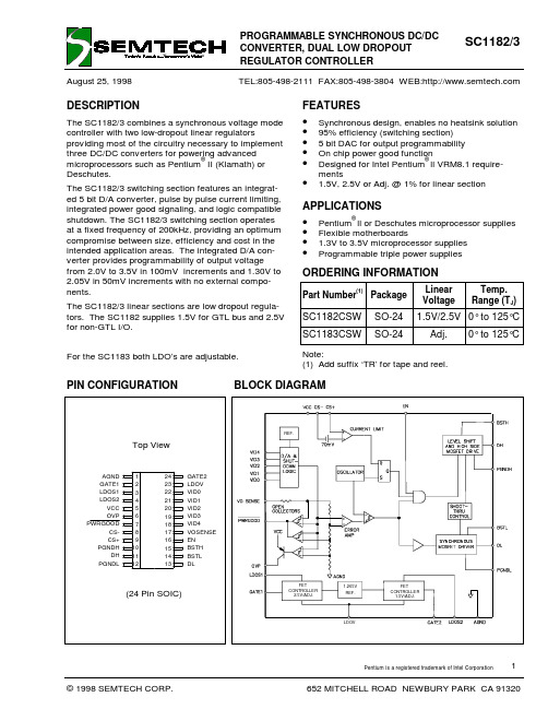
August 25, 1998ORDERING INFORMATIONDESCRIPTIONThe SC1182/3 combines a synchronous voltage mode controller with two low-dropout linear regulatorsproviding most of the circuitry necessary to implement three DC/DC converters for powering advancedmicroprocessors such as Pentium ®II (Klamath) or Deschutes.The SC1182/3 switching section features an integrat-ed 5 bit D/A converter, pulse by pulse current limiting,integrated power good signaling, and logic compatible shutdown. The SC1182/3 switching section operates at a fixed frequency of 200kHz, providing an optimum compromise between size, efficiency and cost in the intended application areas. The integrated D/A con-verter provides programmability of output voltage from 2.0V to 3.5V in 100mV increments and 1.30V to 2.05V in 50mV increments with no external compo-nents.The SC1182/3 linear sections are low dropout regula-tors. The SC1182 supplies 1.5V for GTL bus and 2.5V for non-GTL I/O.For the SC1183 both LDO’s are adjustable.TEL:805-498-2111 FAX:805-498-3804 WEB:BLOCK DIAGRAM2.5V/ADJ.1.5V/ADJ.1.265V FETCONTROLLER REF.FETCONTROLLER REF.LDOVPIN CONFIGURATION AGND GATE1LDOS1LDOS2VCC OVPPWRGOODCS-CS+PGNDHDH PGNDL 123LDOV 456789101112242322212019181716151413VOSENSE EN BSTH BSTL DLVID0VID1VID2VID3VID4GATE2Top View(24 Pin SOIC)FEATURES • Synchronous design, enables no heatsink solution • 95% efficiency (switching section)• 5 bit DAC for output programmability • On chip power good function•Designed for Intel Pentium ®ll VRM8.1 require-ments• 1.5V, 2.5V or Adj. @ 1% for linear sectionAPPLICATIONS • Pentium ®ll or Deschutes microprocessor supplies • Flexible motherboards• 1.3V to 3.5V microprocessor supplies •Programmable triple power suppliesPart Number(1)PackageLinear VoltageTemp.Range (T J )SC1182CSW SO-24 1.5V/2.5V 0° to 125°C SC1183CSWSO-24Adj.0° to 125°CNote:(1) Add suffix ‘TR’ for tape and reel.August 25, 1998Parameter Symbol Maximum Units V CC to GND V IN-0.3 to +7V PGND to GND ± 1V BST to GND-0.3 to +15V Operating Temperature Range T A 0 to +70°C Junction Temperature Range T J 0 to +125°C Storage Temperature RangeT STG -65 to +150°C Lead Temperature (Soldering) 10 seconds T L 300°C Thermal Impedance Junction to Ambient θJA 80°C/W Thermal Impedance Junction to CaseθJC25°C/WABSOLUTE MAXIMUM RATINGSELECTRICAL CHARACTERISTICSUnless specified: V CC = 4.75V to 5.25V; GND = P GND = 0V; V OSENSE = V O ; 0mV < (CSp-CSm) < 60mV; LDOV = 11.4V to 12.6V; T A = 25°CPARAMETERCONDITIONS MIN TYP MAX UNITSSwitching Section Output Voltage I O = 2A See Note 1.Supply Voltage V CC4.27V Supply Current V CC = 5.0815mA Load Regulation I O = 0.8A to 15A1%Line Regulation0.5%Minimum operating voltage 4.2V Current Limit Voltage 607080mV Oscillator Frequency180200220kHz Oscillator Max Duty Cycle 9095%Peak DH Sink/Source Current BSTH-DH = 4.5V, DH-PGNDH = 2V 1A Peak DL Sink/Source Current BSTL-DL = 4.5V, DL-PGNDL = 2V 1A Output Voltage Tempco 30100ppm/oC Gain (A OL )V OSENSE to V O 35dB OVP threshold voltage 120%OVP source currentV OVP = 3.0V10mA Power good threshold voltage 88112%Dead time50100ns Linear Sections Quiescent currentLDOV = 12V5mA Output Voltage (LDO1 SC1182) 2.475 2.500 2.525V Output Voltage (LDO2 SC1182) 1.485 1.500 1.515V Reference Voltage (SC1183)1.252 1.265 1.278V Feedback Pin Bias Current (SC1183)10uA Gain (A OL )LDOS (1,2) to GATE (1,2)90dB Load Regulation I O = 0 to 8A(2)0.3%Line Regulation 0.3%Output Impedance200ΩAugust 25, 1998Note:(1) All logic level inputs and outputs are open collector TTL compatible.PIN DESCRIPTIONPin Pin Name Pin Function1AGND Small Signal Analog and Digital Ground 2GATE1Gate Drive Output LDO13LDOS1Sense Input for LDO14LDOS2Sense Input for LDO25VCC Input Voltage6OVPHigh Signal out if V O >setpoint +20%7PWRGOOD (1)Open collector logic output, high if V O within 10% of setpoint8CS-Current Sense Input (negative)9CS+Current Sense Input (positive)10PGNDH Power Ground for High Side Switch 11DHHigh Side Driver Output12PGNDL Power Ground for Low Side Switch 13DL Low Side Driver Output 14BSTL Supply for Low Side Driver 15BSTH Supply for High Side Driver16EN (1)Logic low shuts down the converter;High or open for normal operation.17VOSENSETop end of internal feedback chain 18VID4(1)Programming Input (MSB)19VID3(1)Programming Input 20VID2(1)Programming Input 21VID1(1)Programming Input22VID0(1)Programming Input (LSB)23LDOV +12V for LDO section 24GATE2Gate Drive Output LDO2AGND GATE1LDOS1LDOS2VCC OVPPWRGOODCS-CS+PGNDHDH PGNDL123LDOV 456789101112242322212019181716151413VOSENSE EN BSTH BSTL DLVID0VID1VID2VID3VID4GATE2Top View(24 Pin SOIC)August 25, 1998OUTPUT VOLTAGEUnless specified: V CC = 4.75V to 5.25V; GND = PGND = 0V; V OSENSE = V O ; 0mV < (CSp-CSm) < 60mV; T A = 25°CPARAMETER CONDITIONSVID43210MIN TYP MAX UNITS Output VoltageI O = 2A in Application circuit01111 1.287 1.300 1.313V01110 1.336 1.350 1.36401101 1.386 1.400 1.41401100 1.435 1.450 1.46501011 1.485 1.500 1.51501010 1.534 1.550 1.56601001 1.584 1.600 1.61601000 1.633 1.650 1.66700111 1.683 1.700 1.71700110 1.732 1.750 1.76800101 1.782 1.800 1.81800100 1.831 1.850 1.86900011 1.881 1.900 1.91900010 1.930 1.950 1.97000001 1.980 2.000 2.02000000 2.029 2.050 2.07111111 1.980 2.000 2.02011110 2.079 2.100 2.12111101 2.178 2.200 2.22211100 2.277 2.300 2.32311011 2.376 2.400 2.42411010 2.475 2.500 2.52511001 2.574 2.600 2.62611000 2.673 2.700 2.72710111 2.772 2.800 2.82810110 2.871 2.900 2.92910101 2.970 3.000 3.03010100 3.069 3.100 3.13110011 3.168 3.200 3.23210010 3.267 3.300 3.33310001 3.366 3.400 3.434100003.4653.5003.535August 25, 1998V C C _C O R EV L I N 1V L I N 2G N DV I D 0 V I D 1 V I D 2 V I D 3 V I D 412V5VE NO V PP W R G D5V5VC 1 0.1u FL 1 4u HR 4 5m O h mC 180.1u F+ C 141500u F+ C 15 1500u F+ C 161500u F+C 171500u F+C 3 1500u F+C 2 1500u FR 1 10C 13 0.1u FQ 2 B U K 556Q 1 B U K 556C 5 0.1u FQ 3B U K 556+ C 11330u F+C 12330u FR 52.32kU 1S C 1182/3C S WA G N D1 V C C 5O V P 6 P W R G O O D 7C S -8C S +9P G N D H10 D H 11 B S T H 15 E N16 V O S E N S E 17V I D 418V I D 3 19 V I D 2 20 V I D 1 21 V I D 0 22 D L 13 P G N D L12 B S T L 14 G A T E 2 24 G A T E 1 2 L D O V 23 L D O S 13L D O S 24Q 4B U K 556+ C 9330u F+ C 10330u FR 6 1.00k R 12R 13* R 15R 14+C 21330u F+ C 22330u FR 1610k ***N O T E : F O R S C 1182, R 12,R 13,R 14 A N D R 15 A R E N O T R E Q U I R E D .C O N N E C T LD O S 1 (P I N 3) A N D L D O S 2 (P I N 4) D I RE C T L Y G E N E R A T E 2.5V A N D 1.5V O U T P U T S .T O V L I N 1 A N D V L I N 2 R E S P E C T I V E L Y T O* S E E "S E T T I N G L D O O U T P U T V O L T A G E " T A B L ER 17100KR 18100KAPPLICATION CIRCUITAugust 25, 1998SETTING LDO OUTPUT VOLTAGEMATERIALS LISTQty.Reference Part/Description Vendor Notes4C1,C5,C13,C180.1µF Ceramic Various 6C2,C3,C14-C171500µF/6.3V SANYO MV-GX or equiv. Low ESR 6C9-C12,C21, C22330µF/6.3V Various1L14µH 8 Turns 16AWG on MICROMETALS T50-52D core 4Q1,Q2,Q3,Q4See notes See notes FET selection requires trade-off between efficiency and cost. Absolute maximum R DS(ON) = 22 m Ω for Q1,Q21R45m ΩIRC OAR-1 Series1R5 2.32k Ω, 1%, 1/8W Various 1R61k Ω, 1%, 1/8W Various 1R110Ω, 5%, 1/8W Various 1R121%, 1/8W Various See Table Below (Not required for SC1182)1R131%, 1/8W Various See Table Below (Not required for SC1182)1R141%, 1/8W Various See Table Below (Not required for SC1182)1R151%, 1/8W Various See Table Below (Not required for SC1182)2R17, R18100K, 5%, 1/8W Various 1U1SC1182/3CSWSEMTECHerrort significan cause not does term )R I ( the that so enough low be must R and R ion clarificat for diagram layout See resistor feedback Bottom R resistor feedback Top R current bias pin Feedback I :Where )R I (R )R R (265.1V A FB B A B A FB A FB BB A OUT ⋅===⋅++⋅=R BR AVOUT LDO1 (LDO2)R12 (R14)R13 (R15)3.45V 105Ω182Ω3.30V 105Ω169Ω3.10V 102Ω147Ω2.90V 100Ω130Ω2.80V 100Ω121Ω2.50V 100Ω97.6Ω1.50V100Ω18.7ΩAugust 25, 199870%75%80%85%90%95%246810121416Io (Amps)E f f i c i e n c y3.5V Std 3.5V Sync3.5V Sync Lo Rds70%75%80%85%90%95%246810121416Io (Amps)E f f i c i e n c y2.5V Std 2.5V Sync2.5V Sync Lo Rds70%75%80%85%90%95%246810121416Io (Amps)E f f i c i e n c y2.8V Std 2.8V Sync2.8V Sync Lo Rds70%75%80%85%90%95%246810121416Io (Amps)E f f i c i e n c y2.0V Std 2.0V Sync2.0V Sync Lo RdsTypical Ripple, Vo=2.8V, Io=10A Typical Efficiency at Vo=2.5V Typical Efficiency at Vo=3.5VTypical Efficiency at Vo=2.8VTypical Efficiency at Vo=2.0VTransient Response Vo=2.8V, Io=300mA to 10AAugust 25, 1998LAYOUT GUIDELINESCareful attention to layout requirements are necessary for successful implementation of the SC1182/3 PWM controller. High currents switching at 200kHz are pre-sent in the application and their effect on ground plane voltage differentials must be understood and mini-mized.1). The high power parts of the circuit should be laid out first. A ground plane should be used, the number and position of ground plane interruptions should be such as to not unnecessarily compromise ground plane integrity. Isolated or semi-isolated areas of the ground plane may be deliberately introduced to constrain ground currents to particular areas, for example the input capacitor and bottom FET ground.2). The loop formed by the Input Capacitor(s) (Cin), the Top FET (Q1) and the Bottom FET (Q2) must be keptas small as possible. This loop contains all the high current, fast transition switching. Connections should be as wide and as short as possible to minimize loop inductance. Minimizing this loop area will a) reduce EMI, b) lower ground injection currents, resulting in electrically “cleaner” grounds for the rest of the system and c) minimize source ringing, resulting in more reli-able gate switching signals.3). The connection between the junction of Q1, Q2 and the output inductor should be a wide trace or copper region. It should be as short as practical. Since this connection has fast voltage transitions, keeping this connection short will minimize EMI. The connection between the output inductor and the sense resistor should be a wide trace or copper area, there are no fast voltage or current transitions in this connection and length is not so important, however adding unnec-essary impedance will reduce efficiency.Vout12V IN5VVo Lin1Vo Lin25V4uH5mOhm+Cout+Cin10Q 20.1uFQ 3+Cout Lin12.32kQ 4+Cout Lin21.00kR B 1RA1RA2R B 2+Cin LinSC1182/3AGND 1V C C 5O V P 6P W R G O O D 7CS-8C S +9P G N D H 10DH 11BSTH 15EN 16VO SENSE17VID418VID319VID220VID121VID022D L13P G N D L12B S T L 14GATE224GATE12L D V O 23L D O S 13L D O S 24Q 10.1uFHeavy lines indicate high current paths.are not required. LDOS1 connects to For SC1182, RA1, RA2, RB1 and RB2Vo Lin1, LDOS2 connects to Vo Lin2Layout diagram for the SC1182/3August 25, 1998Vout5V++4) The Output Capacitor(s) (Cout) should be located as close to the load as possible, fast transient load currents are supplied by Cout only, and connections between Cout and the load must be short, wide cop-per areas to minimize inductance and resistance.5) The SC1182/3 is best placed over a quiet ground plane area, avoid pulse currents in the Cin, Q1, Q2loop flowing in this area. PGNDH and PGNDL should be returned to the ground plane close to the package.The AGND pin should be connected to the ground side of (one of) the output capacitor(s). If this is not possible, the AGND pin may be connected to the ground path between the Output Capacitor(s) and the Cin, Q1, Q2 loop. Under no circumstances should AGND be returned to a ground inside the Cin, Q1, Q2loop.6) Vcc for the SC1182/3 should be supplied from the5V supply through a 10Ω resistor, the Vcc pin should be decoupled directly to AGND by a 0.1µF ceramic capacitor, trace lengths should be as short as possi-ble.7) The Current Sense resistor and the divider across it should form as small a loop as possible, the traces running back to CS+ and CS- on the SC1182/3should run parallel and close to each other. The 0.1µF capacitor should be mounted as close to the CS+ and CS- pins as possible.8) Ideally, the grounds for the two LDO sections should be returned to the ground side of (one of) the output capacitor(s).Currents in various parts of the power sectionAugust 25, 1998COMPONENT SELECTIONSWITCHING SECTION OUTPUT CAPACITORS - Selection begins with the most critical component. Because of fast transient load current requirements in modern microprocessor core supplies, the output capacitors must supply all transient load current requirements until the current in the output inductor ramps up to the new level. Output capacitor ESR is therefore one of the most important criteria. The maximum ESR can be simply calculated from:stepcurrent Transient I excursion voltage transient Maximum V WhereI V R t t tt ESR==≤Each CapacitorTotal Technology C (µF)ESR (m Ω)Qty.Rqd.C (µF)ESR (m Ω)Low ESR Tantalum 330606200010OS-CON3302539908.3Low ESR Aluminum150044575008.8()O IN tESR V V I CR L −≤OSCIN L f L 4V I RIPPLE ⋅⋅=INO)on (DS 2O COND V V cycle duty = whereR I P ≈δδ⋅⋅=2IN O SW 10V I P −⋅⋅=4f )t t (V I P OSCf r IN O SW ⋅+⋅⋅=OSCIN RR RR f V Q P ⋅⋅=For example, to meet a 100mV transient limit with a 10A load step, the output capacitor ESR must be less than 10m Ω. To meet this kind of ESR level, there are three available capacitor technologies.The choice of which to use is simply a cost/perfor-mance issue, with Low ESR Aluminum being the cheapest, but taking up the most space.INDUCTOR - Having decided on a suitable type and value of output capacitor, the maximum allowable value of inductor can be calculated. Too large an in-ductor will produce a slow current ramp rate and will cause the output capacitor to supply more of the tran-sient load current for longer - leading to an output volt-age sag below the ESR excursion calculated above.The maximum inductor value may be calculated from:The calculated maximum inductor value assumes 100%duty cycle, so some allowance must be made. Choosing an inductor value of 50 to 75% of the calculated maxi-mum will guarantee that the inductor current will rampfast enough to reduce the voltage dropped across the ESR at a faster rate than the capacitor sags, hence en-suring a good recovery from transient with no additional excursions.We must also be concerned with ripple current in the output inductor and a general rule of thumb has been to allow 10% of maximum output current as ripple current.Note that most of the output voltage ripple is produced by the inductor ripple current flowing in the output ca-pacitor ESR. Ripple current can be calculated from:Ripple current allowance will define the minimum per-mitted inductor value.POWER FETS - The FETs are chosen based on sev-eral criteria with probably the most important being power dissipation and power handling capability.TOP FET - The power dissipation in the top FET is a combination of conduction losses, switching losses and bottom FET body diode recovery losses.a) Conduction losses are simply calculated as:b) Switching losses can be estimated by assuming a switching time, if we assume 100ns then:or more generally,c) Body diode recovery losses are more difficult to esti-mate, but to a first approximation, it is reasonable to as-sume that the stored charge on the bottom FET body diode will be moved through the top FET as it starts to turn on. The resulting power dissipation in the top FET will be:To a first order approximation, it is convenient to only consider conduction losses to determine FET suitability.For a 5V in; 2.8V out at 14.2A requirement, typical FET losses would be:August 25, 1998)1(R I P )on (DS 2O COND δ−⋅⋅=FET typeR DS(on) (m Ω)P D (W)Package BUK556H 22 2.48TO220IRL22037.00.79D 2PAK Si441013.51.53SO-8FET type R DS(on) (m Ω)P D (W)Package BUK556H 221.95TO220IRL22037.00.62D 2PAK Si441013.51.20SO-8BOTTOM FET - Bottom FET losses are almost entirely due to conduction. The body diode is forced into con-duction at the beginning and end of the bottom switch conduction period, so when the FET turns on and off,there is very little voltage across it, resulting in lowswitching losses. Conduction losses for the FET can be determined by:For the example above:Each of the package types has a characteristic thermal impedance, for the TO-220 package, thermalimpedance is mostly determined by the heatsink used.For the surface mount packages on double sided FR4, 2oz printed circuit board material, thermal impedances of 40o C/W for the D 2PAK and 80oC/W for the SO-8 are readily achievable. The corresponding temperature rise is detailed below:Temperature rise (oC)FET type Top FETBottom FET BUK556H 49.6(1)39.0(1)IRL220331.624.8Si4410122.496(1) With 20oC/W HeatsinkIt is apparent that single SO-8 Si4410 are not adequate for this application, but by using parallel pairs in each po-sition, power dissipation will be approximately halved and temperature rise reduced by a factor of 4.INPUT CAPACITORS - since the RMS ripple currentin the input capacitors may be as high as 50% of the output current, suitable capacitors must be chosen ac-cordingly. Also, during fast load transients, there may be restrictions on input di/dt. These restrictions require useable energy storage within the converter circuitry,either as extra output capacitance or, more usually,additional input capacitors. Choosing low ESR input capacitors will help maximize ripple rating for a given size.August 25, 1998OUTLINE DRAWINGJEDEC MS-013ADB17104B。
ACS SPiiPlusSC Troubleshooting
SpiiPlusSC Motion ControllerTroubleshooting GuideSPiiPlusSC Motion ControllerVersion SC 2.20COPYRIGHTCopyright ® 1999 - 2013 ACS MotionControl Ltd.Changes are periodically made to the information in this document. Changes are published as release notes and are subsequently incorporated into revisions of this document.No part of this document may be reproduced in any form without prior written permission from ACS MotionControl.TRADEMARKSACS MotionControl, PEG and SPii are trademarks of ACS MotionControl Ltd.EtherCAT® is registered trademark and patented technology, licensed by Beckhoff Automation GmbH, Germany.Visual Basic and Windows are trademarks of Microsoft Corporation.Any other companies and product names mentioned herein may be the trademarks of their respective owners.Web Site: Information: info@Tech Support: support@ ACS Motion Control, Ltd.Ramat Gabriel Industrial ParkPOB 5668Migdal HaEmek, 10500ISRAELTel: (972) (4) 6546440Fax: (972) (4) 6546443NOTICEThe information in this document is deemed to be correct at the time of publishing. ACS MotionControl reserves the right to change specifications without notice. ACS MotionControl is not responsible for incidental, consequential, or special damages of any kind in connection with using this document.SPiiPlusSC Motion ControllerRelated DocumentsThe following documents provide additional details relevant to this guide:About This DocumentThis document covers all known issues for SPiiPlusSC Motion Controller and provides detailed step-by-step instructions. The soltions are based on a three-step approach: detecting the problem, suggesting possible causes, and resolving the problem.SPiiPlusSC Motion Controller Table of ContentsTable of Contents1SPiiPlusSC Installation Version . . . . . . . . . . . . . . . . . . . . . . . . . . . . . . . . . . . . . . 1 2Troubleshooting . . . . . . . . . . . . . . . . . . . . . . . . . . . . . . . . . . . . . . . . . . . . . . . . . . . 2 2.1The output in UMD "freezes" after displaying "checking license….OK" . . . . . 2 1.2Communication with SPiiPlusSC is being lost periodically . . . . . . . . . . . . . . . 5 1.3MMI Application Studio loses communication with SPiiPlusSC when theapplication is not on the host PC . . . . . . . . . . . . . . . . . . . . . . . . . . . . . . . . . . . . . . .5SPiiPlusSC Motion Controller SPiiPlusSC Installation Version 1SPiiPlusSC Installation VersionUse this guide when the SPiiPlusSC 2.20 official version is installed on the host PC.2Troubleshooting2.1The output in UMD "freezes" after displaying"checking license….OK"Full DescriptionAfter clicking "Start SPiiPlusSC" button in the UMD, the last line that can be seen in the Controller Output window is "checking license…OK".Possible Cause 1IP address of SPiiPlusSC is not in the same subnet as the IP address of the Virtual Network Adapter. For example, SPiiPlusSC has the following IP address: 192.168.157.20, while the Virtual Network Adapter has the following IP address: 169.168.158.19.SolutionSet a static IP address for Virtual Network Adapter. The IP address should be in the same subnet, for example: 192.168.157.4Possible Cause 2For Windows 7 only, it is possible that after installing a new driver for the network adapter or that a network bridge was set and then deleted, NetBIOS disables communication with SPiiPlusSC.SolutionRun the DisableNetBIOS utility that fixes this issue (part of the installation). Note that the computer must be restarted after running the utility.Default path on X64 platform:C:\Program Files\ACS Motion Control\SPiiPlusSC\x64\DisableNetBIOS_x64.exeDefault path on X86 platform:C:\Program Files\ACS Motion Control\SPiiPlusSC\x86\DisableNetBIOS_x86.exe Possible Cause 3The cause might be an expired password.SolutionReset the spiiPlusSC user password.1.Select Computer Management > Local Users and Groups > Users.2.Right-click spiiplussc, select set password, and type the same password that appears inthe user mode driver.3.Right-click spiiplussc, select properties, and check the Password never expires option.1.2Communication with SPiiPlusSC is being lostperiodicallyFull DescriptionSPiiPlusSC starts OK and communication is established from the MMI Application Studio. However, after a few seconds communication is lost.Possible CauseThere is an additional SPiiPlusSC Controller in the same network (LAN) with the same MAC Address. MAC Addresses must be unique within the same network.SolutionChange the MAC Address of the SPiiPlusSC Controller in the User Mode Driver\SPiiPlusSC tab.1.3MMI Application Studio loses communication withSPiiPlusSC when the application is not on the host PC Full DescriptionSPiiPlusSC starts OK. The MMI Application Studio connects to SPiiPlusSC from another computer (can be via bridge or point to point), but after a few minutes the communication is lost.Possible CauseWindows 7 power management option put computer to sleep is checked. This means that after X minutes, Windows enters sleep mode and SPiiPlusSC disconnects.SolutionSet the put computer to sleep option to Never:。
SC451中文资料

SC451Portable IMVP-IV™ and IMVP-IV+™Single Phase Power Supply Controller!IMVP-IV™ and IMVP-IV+™ compliant single chip solution!On-chip CLK_ENABLE# and IMVP4_PWRGD outputs !Backward compatible with SC1479!High-speed hysteretic controller !Single-phase operation!Selectable analog or VID controlled DeeperSleep setting! 6 bit VID programmable output!Integrated drivers with soft high side turn-on !Programmable softstart !Programmable boot voltage!Programmable DeeperSleep voltage !Under-voltage lock out on VccA !Over-voltage protection on CORE !Current limit protection on CORE !Thermal protection!Powergood flag with blanking during VID or DeeperSleep mode changes!Automatic powersave at light load!TSSOP-28 and TSSOP-38 package optionsThe SC451 PowerStep IV™ IC is a single chip high-perfor-mance Hysteretic PWM controller. With its integrated SmartDriver™, it powers advanced IMVP-IV™ and IMVP4+™processors. The SC451 features extended Intel Mobile Volt-age Positioning (IMVP™) to increase battery life by reduc-ing the voltage at the processor when it is heavily loaded.It directly supports Intel’s SpeedStep® processors for even longer battery life. The SC451 fully supports the Intel®Geyserville-III core voltage specification. It provides direct “deeper sleep” mode and boot voltage support. Automatic “power-save” is present to prevent negative current flow in the low-side FET during light loading conditions, saving even more power. The high side driver initially turns on with a weak drive to reduce ringing, EMI, and capacitive turn-on of the low side.A 6-bit DAC, accurate to 0.85%, sets the output voltage reference, and implements the 0.700V to 1.708V range required by the processor. The hysteretic converter uses acomparator without an error amplifier, and therefore pro-vides the fastest possible transient response, while avoid-ing the stability issues inherent to classical PWM control-lers. The DAC is externally slew rate limited to minimize transient currents and audible noise.The SC451 operates from 5VDC and also features soft-start, an open-drain PWRGD signal with power-good blank-ing, and an enable input. Programmable current limiting shuts down the SC451 after 32 current limit pulses. It comes in both a TSSOP-28 and TSSOP-38 package. The TSSOP-38 provides a pin-to-pin upgrade to a dual-phase solution using Semtech’s dual-phase controller, SC450.!Low power Notebook and Laptop computers !Embedded ApplicationsPowerStep IV™ is a trademark of Semtech Corporation.Other trademarks or registered trademarks may be claimed as the property of others.。
SC6610配置注意事项V1.0
基地址
代码应用
其它
GPIO71是内部使用
2011-4-20
保密信息
.7
SPI Port
• SC6610在扩展性上主要选择SPI来承担,故存在较多的SPI Port选择。可能在本 文档的SPI LCD部分的描述已经造成了一些困扰,这里希望能将其说明清楚。 SPIX_X_CSX的格式解释如下:(后续会修改为SPIX_PADX_CSX的格式) 分为三部分:Controller,Pad,CS,由他们共同来输入给驱动软件如何正确完成 对指定SPI的操作。
3、 s_main_lcm_cfg_tab 结构体内cs_pin必须为SPIX_X_CSX的形式,一般不需要改变,默认为 SPI1_1_CS0,若存在改变,具体的值应该向硬件咨询到Chip PAD,再根据SC6610 Spec查找到合适的 SPIX_X_CSX。(若这部分或第5小点存在疑问,可以参考本文档SPI Port章节); 4、 s_main_lcm_cfg_tab 结构体内cd_pin应根据硬件对应的GPIO,写成GPIO_NUM(X)的形式,千万 不能丢掉GPIO_NUM,这是和6600L一个明显的配置差别; 5、若需要支持SPI LCD通过ID方式的自适应,必须注意Pin复用功能:当前SPIX_X_CSX组可以复用成 GPIO的,他们是SPI0_0_CS0, SPI0_0_CS1,SPI1_0_CS0,SPI1_1_CS0, SPI1_1_CS1;不能复 用为GPIO的为SPI1_2_CS0, SPI1_2_CS2;我们最推荐还是默认的SPI1_1_CS0,因为他们是和并口屏 的LCMD复用的,这个定位的项目一般不需要双屏,在确定SPI屏的情况下,不需要并口屏,这样就有更多的 SPI Port留出来备用; 6、对应的tft_xxx_spi.c驱动文件中,需要注意s_xxx_spitiming[]时序和SC6600L不同,由 SPI_CLK_IDLE_XXX和SPI_SAMPLING_XXX共同决定了SPI时序的四种模式哪一种,另外部分请以平台已有的 tft_ili9225b_spi.c作为参考; 7、SPI LCD Reset线连接LCM Rstn管脚,若硬件修改为连接GPIO,需要在tft_xxx_spi.c中实现void (*lcd_Rst) (void)函数操作GPIO,并注册该接口。
DSP连接不上
关于DSP的JTAG连不上的解决办法若JTAG不能识别TI的DSP,则可能存在以下几个方面的原因:若JTAG不能识别TI的D SP,则可能存在以下几个方面的原因:1、仿真器有问题;2、仿真器的驱动有问题;3、目标板有问题;在此,我们只讨论仿真器没问题,和仿真器的驱动正确安装,而因目标板的原因导致JTAG连不上的情况:1、检查DSP的供电(Core电压,IO电压)是否正确?纹波是否满足要求? 上电顺序是否满足要求?2、检查DSP的供电始终是否正确?电平是否满足要求?3、检查DSP的系统复位信号是否正常?NMI管脚的接法是否正确?DSP相关的所有输入脚的接法是否正确?4、测量DSP的CLKOUT是否正确?测量上电时,DSP是否会去片选boot-Flash?5、测量DSP的EMIF总线,任意两个数据线或地址线不要有短路或接错的现象;若有条件,可对EMIF总线上的负载断开再进行JTGA连接测试;6、若DSP的EMIF总线上,有FPGA设备,则需要先下载FPGA的程序。
可把与DSP相关的FPGA所有信号都定义为输入;7、正确设置CCS,打开CCS后,点击debug中reset后,若不报错,则一般驱动都没有问题;8、手动多次复位DSP后再尝试连接,或连接失败后重启CCS和计算机;DSP为啥连接不上?TMS320C6416T+seed-XDS510 PLUS分类:DSP 2012-06-02 11:03130人阅读评论(0)收藏举报题目:DSP为啥连接不上?TMS320C6416T+seed-XDS510 PLUS平台:TMS320C6416T仿真器:seed-XDS510 PLUS最经常出现的错误:(因为出现过很多种错误,这是出现次数最多的一个)Error connecting to the target:Error 0x80002262/-116Fatal Error during: Memory, Execution, Initialization, OCS, Control,This error was generated by TI's USCIF driver.SC_ERR_CTL_TRASH <-116>A bad parameter value was detected within an internal data-structure of Unified-SCIF. The controller or Unified-SCIF may be in an invalid state.Sequence ID: 0Error Code: -116Error Class: 0x80002262I/O Port = 240Board Name: C64xx SEEDXDS510PLUS Emulator_1Cpu Name: TMS320C6400_0Abort: Close Code Composer Studio.Retry: Try to connect to the target again.Cancel: Remain disconnected from the targetDiagnostic: Run diagnostic utility.分析原因:(以下是来自互联网的一些解决办法,也包含自己的一些观点,由于参考网址较多,没有一一贴出来源,敬请作者谅解!)1、重装CCS这一项还是不要轻易采用了吧。
SN8P2501B_SC
SC1101CS资料
POWER MANAGEMENTSC1101Asynchronous Voltage Mode PWM ControllerFeaturesApplicationsDescriptionLow cost / small sizeSwitch mode efficiency up to 95% 1% reference voltage accuracy Over current protection 500mA output driveSO-8 packagePentium® P55 Core SupplyLow Cost Microprocessor Supplies Peripheral Card Supplies Industrial Power SuppliesHigh Density DC/DC ConversionThe SC1101 is a versatile, low-cost, voltage-mode PWM controller designed for low output voltage DC/DC power supply applications. A simple, fixed-voltage buck regulator can be implemented using the SC1101 with a minimum of external components. Internal level shift and drive circuitry eliminates the need for an expensive p-channel, high-side switch. The small device footprint allows for compact circuit design.SC1101 features include a temperature compensated voltage reference, triangle wave oscillator, current limit comparator, frequency shift over-current protection, and an internally compensated error amplifier. Pulse by pulse current limiting is implemented by sensing the differential voltage across an external resistor, or an appropriately sized PC board trace.The SC1101 operates at a fixed frequency of 200kHz,providing an optimum compromise between efficiency,external component size, and cost.Electrical CharacteristicsAbsolute Maximum Ratingsr e t e m a r a P l o b m y S m u m i x a M s t i n U e g a t l o V t u p n I V C C D N G o t 7+o t 3.0-V l a i t n e r e f f i D d n u o r G P D N G D N G o t 1±V eg a t l o V t u p n I t s o o B DN G o t T S B 51+o t 3.0-V e g n a R e r u t a r e p m e T t n e i b m A g n i t a r e p O T B M A 07+o t 0C °e g n a R e r u t a r e p m e T e g a r o t S T G T S 521o t 54-C °e r u t a r e p m e T n o i t c n u J m u m i x a M T J 521C °.c e S 01)g n i r e d l o S (e r u t a r e p m e T d a e L T D A E L 003C °t n e i b m A o t n o i t c n u J e c n a t s i s e R l a m r e h T θA J 561W /C °es a C o t n o i t c n u J e c n a t s i s e R l a m r e h T θCJ 04W/C °r e t e m a r a P l o b m y S s n o i t i d n o C n i M p y T x a M s t i n U ec n e r e f e R V FE R 832.1052.1362.1Veg n a r .p m e T C °521o t 0r e v O 522.1052.1572.1t n e r r u C s a i B k c a b d e e F I B F 0.20.8A u t n e r r u C t n e c s e i u Q I QV o t n i t n e r r u C C C n i p 0.50.8A m n o i t a l u g e R d a o L I O A 01o t A 1=5.00.1%n o i t a l u g e R e n i L I O A 01=5.0%d l o h s e r h T t i m i L t n e r r u C )-(S C o t )+(S C 060708V m y c n e u q e r F r o t a l l i c s O 071002032z H k t f i h S y c n e u q e r F r o t a l l i c s O V B F V <F E R 2/05z H k e l c y C y t u D x a M 0959%t n e r r u C e c r u o S /k n i S H D I O V T S B V -H D V /V 5.4=H D V -D N G P V2=005Am dl o h s e r h T O L V U V OL V U 8.3VUnless specified: V CC = 4.75 to 5.25, GND = P GND = 0V, V O = 2.5V, T A = 25°C, BST = 12V.Per test circuit, unless otherwise specified.Note:(1) This device is ESD sensitive. Use of standard ESD handling precautions is required.Exceeding the specifications below may result in permanent damage to the device, or device malfunction. Operation outside of the parameters specified in the Electrical Characteristics section is not implied.Pin ConfigurationOrdering InformationPin Descriptionsec i v e D )1(e g a k c a P T (e g n a R p m e T J )R T .S C 1011C S 8-O S C°521o t °0TR T S C 1011C S )2(Notes:(1) Only available in tape and reel packaging. A reel contains 2500 devices.(2) Lead free product. This product is fully WEEE and RoHS compliant.re b m u N n i P e m a N n i P no i t c n u F n i P 1C C V .e g a t lo v t u p n i e c i v e D 2)-(S C .)e v i t a g e N (t u p n i e s n e s t n e r r u C 3)+(S C .)e v i t i s o P (t u p n i e s n e s t n e r r u C 4D N G P .d n u o r g r e w o p e c i v e D 5H D .t u p t u o r e v i r d e d i s h g i H 6T S B V r e v i r d e d i s h g i H C C .)t s o o B (7B F .)-(t u p n i r e i f i l p m a r o r r E 8DN G .d n u o r g l a n g i S Block DiagramCareful attention to layout requirements are necessary for successful implementation of the SC1101 PWM controller. High currents switching at 200kHz are present in the application and their effect on ground plane volt-age differentials must be understood and minimized. 1). The high power parts of the circuit should be laid out first. A ground plane should be used, the number and position of ground plane interruptions should be such as to not unnecessarily compromise ground plane integrity. Isolated or semi-isolated areas of the ground plane may be deliberately introduced to constrain ground currents to particular areas, for example the input capacitor and bottom Schottky ground.2). The loop formed by the Input Capacitor(s) (Cin), the Top FET (Q1) and the Schottky (D1) must be kept as small as possible. This loop contains all the high current, fast transition switching. Connections should be as wide and as short as possible to minimize loop inductance. Mini-mizing this loop area will reduce EMI, lower ground injec-tion currents, resulting in electrically “cleaner” grounds for the rest of the system and minimize source ringing, resulting in more reliable gate switching signals.3). The connection between the junction of Q1, D1 and the output inductor should be a wide trace or copper region. It should be as short as practical. Since this con-nection has fast voltage transitions, keeping this con-nection short will minimize EMI. The connection between the output inductor and the sense resistor should be a wide trace or copper area, there are no fast voltage or current transitions in this connection and length is not so important, however adding unnecessary impedance will reduce efficiency.4) The Output Capacitor(s) (Cout) should be located as close to the load as possible, fast transient load cur-rents are supplied by Cout only, and connections between Cout and the load must be short, wide copper areas to minimize inductance and resistance.5) The SC1101 is best placed over an isolated ground plane area. GND and PGND should be returned to this isolated ground. This isolated ground area should be con-nected to the main ground by a trace that runs from the GND pin to the ground side of (one of) the output capacitor(s). If this is not possible, the GND pin may be connected to the ground path between the Output Capacitor(s) and the Cin, Q1, D1 loop. Under no circum-stances should GND be returned to a ground inside the Cin, Q1, D1 loop.6) Vcc for the SC1101 should be supplied from the 5V supply through a 10Ω resistor, the Vcc pin should be decoupled directly to GND by a 0.1µF ceramic capacitor, trace lengths should be as short as possible.7) The Current Sense resistor and the divider across it should form as small a loop as possible, the traces run-ning back to CS(+) and CS(-) on the SC1101 should run parallel and close to each other.8) To minimize noise pickup at the sensitive FB pin, the feedback resistors should both be close to the SC1101 with the bottom resistor (Rb) returned to ground at the GND pin.Under Voltage LockoutThe under voltage lockout circuit of the SC1101 assures that the high-side MOSFET driver outputs remain in the off state whenever the supply voltage drops below set parameters. Lockout occurs if VCCfalls below 3.8V. Nor-mal operation resumes once VCCrises above 3.8V.Layout Guidelines Applications InformationTypical CharacteristicsError Amplifier, Gain and PhaseLoad Regulation V IN = 5VOutput Ripple VoltageV IN = 5V; V O = 3.3V; I O = 10A。
- 1、下载文档前请自行甄别文档内容的完整性,平台不提供额外的编辑、内容补充、找答案等附加服务。
- 2、"仅部分预览"的文档,不可在线预览部分如存在完整性等问题,可反馈申请退款(可完整预览的文档不适用该条件!)。
- 3、如文档侵犯您的权益,请联系客服反馈,我们会尽快为您处理(人工客服工作时间:9:00-18:30)。
如果您要创建可满足公司 IT 标准和策略要求的服务,就可以利用模板来简化操作。
要获取有关 System Center App Controller 2012 的更多信息,请访问 /systemcenter/appcontroller.
© 2011 Microsoft Corporation。保留所有权利。此一览表仅供参考。MICROSOFT 未在此份摘要信息中做出任何保证、明示或暗示。
System Center App Controller 2012 还让应 用程序所有者能够在公共云和私有云环境 中平滑顺畅地迁移各种应用程序和功能组 件。您可以在多个 Windows Azure 订阅之 间复制 Windows Azure 配置、包文件和 VHD 文件,也可以在两台 System Center Virtual Machine Manager 服务器之间复制 服务模板和资源。
提高可见度和控制力
System Center App Controller 2012 采用基 于 Web 的控制台来为应用程序所有者提 供一个包含他们所使用的所有服务和虚拟 机的综合视图。需要特别指出的是,您将能 够在一个一体化的界面中查看各种私有环 境、公有环境和虚拟环境中的 System Center Machine Manager 服务、Windows Azure 服务和虚拟机。
符合您需求的私有云计算与公共云计算
Microsoft System Center 2012 云计 算与数据中心管理解决方案将为您 的私有云和公共云应用程序及服务 提供一整套具有通用价值的管理工 具集, 将 IT 服务补充到您的企业中。 Microsoft System Center App Controller 2012 将作为该解决方案 的自助服务功能组件, 以此来为应用 程序所有者赋予如下能力: 借助于以服务为中心的直观型操 作界面,同时搭配使用标准模板 库,从而轻松地配置、部署和管 理各种服务。 直接以网页作为操作界面, 根据您在组织中的职位角 色来呈现相应的自定义资 源视图,让您能够将精力集 中于创建、管理和迁移各种 服务之上,而不必再为服务 器大费周折。 查看各种私有云服务和公 共云服务以及各台虚拟机, 并对位于各层组件实现精 密管控,同时,还能够跟踪 各种作业,并保管各种更改 操作的详细历史记录。
/systemcenter/ appcontroller
System Center App Controller 2012您需求的私有云计算与公共云计算
以服务为中心的直观型操作环境
System Center App Controller 2012 具备高度 直观的可视化操作界面,让应用程序所有者 能够轻松管理 System Center Virtual Machine Manager 和 Windows Azure 服务, 并在一个一体化的视图中同时对这两者运 筹帷幄。 利用包含预定义配置值的代理模板库,应用 程序所有者就可以设计、构建、配置和部署 某项服务。通过将公司的 IT 相关标准和策 略植入预定义模板,就可以让数据中心管理 员更有把握地将相关权利委派给应用程序 所有者。 另外,应用程序所有者可以轻松地对指定服 务所包含的所有组件进行自定义,其中包括 虚拟机、网络资源以及负载平衡功能。您还 可以根据应用需求,来对 System Center Virtual Machine Manager 和 Windows Azure 服务的规模和尺度实现扩展或收缩,从而有 效利用多项订阅中所包含的运算功能。
授权给应用程序的所有者
随着 IT 行业的不断发展,企业中将出现两种截然不同的角色:服务提供者(通常是数据 中心管理员)和服务使用者(即应用程序所有者) 。服务提供者负责为服务使用者构建基础 架构以及分配运算资源、存储空间和云计算能力。在给定的云计算能力这一前提下,他们 还需要考虑到合规性、安全性、生产工艺控制以及可用性。随着云计算技术的发展壮大, 对此类角色的需求也在不断增长, 当然, 服务提供者的职能发挥限度仍必须受到现有 IT 预 算框架的约束。 服务使用者具有各种各样的需求。他们希望应用程序具备便于构建和更改的特点,同时, 应用程序的规模也要易于扩展或收缩,总之,要依他们的需求而变。当然,运算职能的取 舍权目前仍掌握在数据中心管理员手中,因此,当应用程序所有者需要构建新应用程序或 对应用程序做出更改时,通常要受制于这样一个瓶颈。而这一瓶颈可能会导致他们考虑使 用某种公共云服务,以便自己掌握运算职能的取舍权,从而摆脱内部服务提供者所造成的 约束。 进入 System Center App Controller 2012 的世界。它提供了一种简单易行的权利委派机制, 数据中心管理员可以利用它来将自己对各种应用程序和虚拟机的控制权委派给应用程序所 有者。另外,在构建应用程序以及增强应用程序所有者对自己所使用的各种服务、虚拟机 和云的可见性方面,也提供了一种简单明了的自助服务式体验。这就让数据中心管理员可 以把自己的时间和精力集中于管理基础架构,同时,又能让应用程序所有者专注于运行自 己所需的服务,而不必去考虑服务器方面的问题。
通过自助服务途径来为应用程序 所有者授权
利用 System Center App Controller 2012,数 据中心管理员就可以为应用程序所有者创 建一个基于角色的自定义视图,以此来呈现 各种私有云服务和公共云服务,以及各种已 使用和未使用的资源。这样,应用程序所有 者就可以自行管理虚拟机、System Center Virtual Machine Manager 服务和 Windows Azure 服务。
通过这一操作界面,您可以控制和管理服务或 虚拟机的运行状态,并对各层组件实现精密控 制。另外,您还可以轻松跟踪各种作业的执行 进度,并保管各种修订和疑难问题的详细历史 记录。 除此之外,该产品还让 IT 专业人士能够实现 对私有云环境和公共云环境进行统一管理和控 制。这种重要价值不仅体现在维护企业安全性 和满足合规性要求方面,而且,在综合运用各 种云计算模型的组织中,这种重要价值也有助 于确保 IT 专业人员扮演关键角色。