origin使用手册
Robostar入门手册l[CN]
![Robostar入门手册l[CN]](https://img.taocdn.com/s3/m/0c7d1849767f5acfa1c7cd77.png)
■ 从机器人的安装到运行的过程说明顺序1机构部的组装 & 控制器的连线工作<连接Cable 1,2轴><连接Cable 3,4轴>수평다R C 정水平多关节机器人水平多关节机器人正面①②③④⑤⑥<注意>• 电源排线时请检查 DC24V的极性连接是否正确。
• 排线有误时可能会损坏内部元件. 特别是, Common端子的极性一定要正确。
☞ 系统 I/O 没有接线的状态下接通控制器电源时,会发生 " SYSTEM EMERGENCY" Error . 这时的措施请参照以下内容。
☞ PLC 操作板上一般情况下会缺少很多关于机器人的状态表示Lamp, 制作操作板时请参照下图中的内容。
■ 电路图☞ 以下说明对应于 安装了Z轴Air cylinder的Type。
☞ 在Z轴增加了利用 Air cylinder的WeightBalance功能可以 UP 负载的重量, 在Cylinder上连接的 Air电路如下。
☞ 注意事项:开关电磁阀的信号是建议使用 Air press s/w的输出接点信号。
☞ 电路说明① 3port sol v/v :-. 电源 off 状态 (Air供应 停止: Brake 动作) -. 电源 on 状态 (Air 供应 : 消除 Brake)※ 解除刹车Air port 部进入空气推动活塞后Brake金属片会松开活塞可以自由移动。
※ 刹车动作Air port里的空气排出后活塞及金属片恢复原来状态在活塞路径上的刹车动作。
② Press s/w 功能Air切断时空气压力下降,这时低于PRESS开关设定的压力之下时就会输出输出接点信号,该接点信号送到系统I/O EMG时所有作业停止。
③ Precision Regulator 的功能根据挂在上下运动轴的负载的重量调整设定适当的Air量。
如果设定得不好,则上下动作时动作不流畅还会发生很多Error,所以设定适当的量非常重要。
原点复位英语

原点复位英语一、“原点复位”英语:“Origin Reset”或“Zero - point Reset”二、英语释义1. “Origin”:[ˈɒrɪdʒɪn],名词,意思是“起源;原点;出身;开端”。
例如:The origin of this custom is very old.(这个习俗的起源非常古老。
)2. “Reset”:[ˌriːˈset],动词,有“重置;重新设置;复位”的意思。
例如:You need to reset your password.(你需要重置你的密码。
)三、短语1. “perform origin reset”:进行原点复位2. “manual origin reset”:手动原点复位3. “automatic origin reset”:自动原点复位四、单词用法1. “Origin”- 可用于表示事物的起始点,如:The origin of the river is in the mountains.(这条河的源头在山里。
)- 在数学或坐标系统中表示原点,例如:In a Cartesian coordinate system, the origin is (0, 0).(在笛卡尔坐标系中,原点是(0, 0)。
)2. “Reset”- 作为及物动词,后面直接跟宾语,如:Reset the machine to its default settings.(将机器重置为默认设置。
)- 可以用于各种需要重新设置或复位的设备、系统等情境。
五、双语例句1. The robot needs an origin reset before starting a new operation.(机器人在开始新的操作之前需要进行原点复位。
)2. Please perform the origin reset according to the user manual.(请按照用户手册进行原点复位。
JV33中文操作手册

J V33中文操作手册work Information Technology Company.2020YEARTS3操作面板介绍FUNCTION SETUP 功能菜单TYPE.1~4INFORMATION菜单功能MAINTENANCE菜单功能MACHINE SETUP菜单功能MACHINE SETUP2菜单功能#ADJUST菜单功能#TEST菜单功能TS3-1600更换喷头教程校正喷头角度手动校正喷的角度“slant”打点校正校准打点位置需要工具:1、喷头2、喷头清洗工具3、喷头交换液4、镙丝刀5、内六角板手6、放大镜(50倍)操作过程:使用针筒和墨囊连接到喷头慢慢的往喷头打清洁液(每30秒4--5CC)一定要非常缓慢轻柔否则会对喷头造成损坏1、选“SLANT ADJUST”功能选项#ADJUST→HEAD ADJUST→SLANT ADJUST→PRINT STADT2、调整校正扳手掰起两个固定的AD手柄,松开锁扣。
然后再搬动调整手杆。
调整一个相40um请按照以下方式和过程调整右边所示b列和a列宽度为100mm,都是参考上部所示颜色,m 色为a列;c色为b列;2、选择打印速度标准选择“standard””high-speed”工厂默认为“high-speed”.M CC Ma columnb column当喷头右边向后倾斜时(顺时针方向调整)当喷头右边向前的情况(逆时针方向调整)b a3、选择精度标准*DRAFT :720、1440dpi 4\8PASS FINE : 540、1080dpi 6\12PASS*调整所有的DRAFT ,FINE ,DRAFT2,and FINE2模式。
4、打印出“Y return ”和 “Fine Y return ”在校正Y return 后,执行fine 校正 5、察看打印出来的图案 *Y Bi把上下对线最准的输入机器 *Fine Y Bi检查调整到两根长短的线完全重叠在一起校正的范围为:-50—50dot(unit:0.1dot)6、输入校正的值TS3-160日常使用菜单1、抽墨囊时打开电磁阀门菜单:FUNCION #TEST CHECK PATTERN INK CARTRIDGE PACK&END SENSOR<ENT> CARTRIDGE.VALVE2、更改机器语言以便适用于各个软件:FUNCION MACHINE SETUP MRL COMMAND 3、更改清洗强度:FUNCION #PARAMETER INK SYSTEM PARAM 24=1200 改=600 25=1200改=600 44=6000改=3000# CARTRIDGE VA. . . . . . . .。
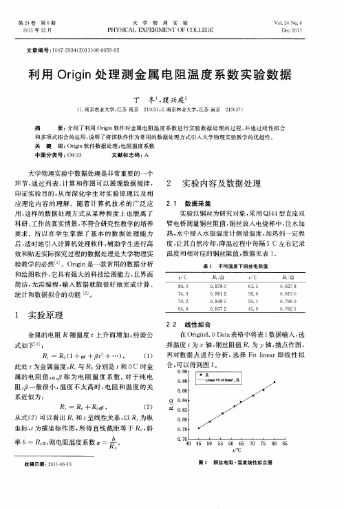
利用Origin处理测金属电阻温度系数实验数据
Ore 的值 为 2 这样得 到 图 2 dr , 。
物理 测量值 . 尤其 是 在 非 线性 拟 合 、 , 曲线 绘 制 和分 析等功 能上 能充分 发挥 计算 机辅 助处 理数 据 的优 势l , 便 了学生进 一步 分析 和挖 掘数 据 , l方 8 进 而引 导学 生进入 数据 规律 的意义 和实 验方 法 的讨 论 中。 因此 将 Or i 件 作 为 常 用 的数 据 处 理 i n软 g 方式 引入 大学 物理 实 验 教 学 中 , 以有 效 提 高 学 可 生利 用计算 机进 行 数 据 处 理 的能 力 , 升 实 验 教 提 学 的质量 。
FANG n. H ANG i o Xi Z Ru— b
( hj n ies y Z e agZ o sa ,1 0 5 Z ei gUnvri ; hj n h uh n 3 0 1 ) a t i
Ab ta t I h sp p rs m ee p e sn y n e n n x e dn fc n e ti r o h o y we e sr c : n t i a e o x rs ig wa sa d m a ig e tn i g o o c p n er rt e r r
臂 电桥 测量 铜丝 阻值 , 铜丝放 入 电烧杯 中, 水加 注 热 , 中浸入 水银 温度计 测量 温度 , 热到一 定程 水 加 度, 让其 自然 冷却 , 降温 过程 中每 隔 5℃ 左右 记 录 温 度和 相对应 的铜 丝 阻值 , 据 见表 l 数 。
表 1 不 同 温 度 下 铜 丝 电 阻值
qss中文手册

qss中文手册QSS(Qt Style Sheets)中文手册QSS,即Qt样式表,是一种用于定义Qt应用程序界面外观的语言。
通过编写QSS样式表,开发人员可以灵活地定制应用程序的外观,从而满足用户的个性化需求。
本文将为您提供一份简明易懂的QSS中文手册,帮助您快速掌握QSS的使用方法和常见特性。
一、什么是QSSQSS是一种基于CSS2.1标准的语言,与HTML和CSS非常相似。
它通过一系列的样式属性来描述应用程序中的控件的外观。
通过使用QSS,您可以自定义控件的背景颜色、字体、边框等样式,以及控件在鼠标悬停或按下状态下的外观。
二、使用QSS的方法1. 在Qt应用程序中使用QSS样式表,可以通过以下两种方式:a) 直接在代码中设置样式表。
您可以在应用程序的代码中使用`setStyleSheet`方法来为某个控件或整个应用程序设置样式表。
```cppwidget->setStyleSheet("background-color: blue;");```b) 使用外部样式表文件。
您可以将样式表保存为一个.qss文件,然后在应用程序中加载并应用它。
例如:```cppQFile styleFile(":/stylesheets/style.qss");styleFile.open(QFile::ReadOnly);QString styleSheet = QLatin1String(styleFile.readAll());app.setStyleSheet(styleSheet);```2. QSS样式表的语法规则和属性值与CSS非常相似。
您可以通过选择器来选择要应用样式的控件,然后设置各种样式属性。
```qssQPushButton {background-color: red;color: white;}```上述示例将所有的QPushButton控件的背景颜色设置为红色,文字颜色设置为白色。
JV33中文操作手册
TS3操作面板介绍FUNCTION SETUP 功能菜单~4INFORMATION菜单功能MAINTENANCE菜单功能MACHINE SETUP菜单功能MACHINE SETUP2菜单功能#ADJUST菜单功能#TEST菜单功能TS3-1600更换喷头教程准备(清洗喷头)由于新喷头内有保护液需要在使用前用弱溶剂清洗掉拆下喷头参考JV5,只要松开三个固定镙丝即可更换新喷头安装上喷头Filling ink操作“fill up”抽出墨水,并以“TEST DRAW”来检查校正喷头角度手动校正喷的角度“slant”打点校正校准打点位置需要工具:1、喷头2、喷头清洗工具3、喷头交换液4、镙丝刀5、内六角板手6、放大镜(50倍)操作过程:使用针筒和墨囊连接到喷头慢慢的往喷头打清洁液(每30秒4--5CC)一定要非常缓慢轻柔否则会对喷头造成损坏1、选“SLANT ADJUST ”功能选项#ADJUST →HEAD ADJUST →SLANT ADJUST →PRINT STADT2、调整校正扳手掰起两个固定的AD 手柄,松开锁 扣。
然后再搬动调整手杆。
调整一个相40um请按照以下方式和过程调整右边所示b 列和a 列宽度为100mm ,都是参考上部所示颜色,m 色为a 列;c 色为b 列;b columna columnb columna column请使用放大镜观查MCCMa columnb column当喷头右边向后倾斜时当喷头右边向前的情况b caumn a caumn2、选择打印速度标准选择“standard ””high-speed ”工厂默认为“high-speed ”.3、选择精度标准*DRAFT :720、1440dpi 4\8PASS FINE : 540、1080dpi 6\12PASS*调整所有的DRAFT ,FINE ,DRAFT2,and FINE2模式。
4、打印出“Y return ”和 “Fine Y return ”在校正Y return 后,执行fine 校正 5、察看打印出来的图案 *Y Bi把上下对线最准的输入机器 *Fine Y Bi检查调整到两根长短的线完全重叠在一起校正的范围为:-50—50dot(unit:6、输入校正的值TS3-160日常使用菜单1、抽墨囊时打开电磁阀门菜单:FUNCION #TEST CHECK PATTERN INK CARTRIDGE PACK&END SENSOR<ENT>2、更改机器语言以便适用于各个软件:FUNCION MACHINE SETUP MRL COMMAND 3、更改清洗强度:FUNCION #PARAMETER INK SYSTEM PARAM# CARTRIDGE VA. . . . .24=1200 改=600 25=1200改=600 44=6000改=3000。
MDI_Jade_使用手册_第四版
一个相一个相地依次精修 晶粒大小和微观应变——计算当晶粒尺寸小于 100nm 时的晶粒大小,如果样品中存在微观
应变,同样可以计算出来 残余应力——残余应力计算功能作为一个特殊附件,某些版本的 Jade 中可能不包含,但是,
PDF2.dat 文件所 在位置,按下 Browse 可查找
要建立的 PDF2 索引所在位置, 不需要更改
开始建立索引
(3)输入 PDF2 光盘中 PDF2.DAT 文件所在位置(已复制到硬盘上),不要使用 Find 命令 让系统去搜索,可以使用 BROWSE 命令自己去查找。 (4)选择需要建立索引的 PDF2 子库,PDF2 中共有 26 万多张卡片,这些卡片按类保存在 不同的子库中,最简单的办法就是“Select All”,因为 JADE 建立的只是索引,而不是完全 复制,所以即使你选择了全部,也多占不了多少硬盘空间。 (5)Go,开始建立索引,建立索引需要大约 10 分钟的时间,这期间你可以做其它的事。 说明: 上图是 JADE5 的界面,JADE6 的界面有一点不同,也没有关系。
2
PDF 卡片索引的建立
PDF 卡片索引的建立
在你使用 JADE 开始如物相检索等工作之前,你需要有一张 PDF2 卡片光盘,并将光盘建立 索引。 目前见到的最新版 PDF2 为 2004 年版,共有 1-54 组(ICDD 收集的卡片)、65 组(通过晶 体结构计算出来的卡片)、70-89 组卡片(引用晶体学数据库的卡片)。实际上 PDF2-2003 版 除没有第 54 组外,其它都差不多,刻意追求哪个版本没有太多的意义。如果你的 PDF2 光 盘上没有你研究的物相,也许更新版的一样没有。如果你的 Jade 版本是 5.0,建议使用 PDF2-2003 版,如果是 6.0,则建议使用 PDF2-2004 版。因为一个软件版本是与相应年份的 PDF 卡片数据库相匹配的,一个低版本软件中使用高版本的卡片库,不但不能增加卡片的 数量反而会使某些卡片无法建立索引。 下面介绍建立 PDF 卡片索引的方法 (1)将 PDF 光盘内容复制到一个容量较大的硬盘分区上(使用起来会方便得多)。在这里 我们实际上要用到的是 PDF2.dat 这个文件,因此,不需要使用 PDF2 光盘上的安装程序来 安装,只需要复制就 OK 了。 (2)选择菜单 PDF-Setup 命令,见到索引窗口:
纳雷科技 CAR28T 毫米波雷达 应用手册说明书
CAR28T毫米波雷达应用手册湖南纳雷科技有限公司免责声明欢迎您选购本产品。
纳雷科技公司官网有CAR28T的专题网页,您可以通过该页面获得最新的产品信息及应用手册。
应用手册如有更新,恕不另行通知。
任何用户在使用本产品前,请仔细阅读本声明。
一旦使用,即被视为对本声明内容的认可和接受。
请严格遵守手册安装与使用该产品。
如有不正当的使用,而造成的损害或损伤,纳雷科技不承担相应的损失及赔偿责任。
本产品为纳雷科技版权所有。
未经许可,不得以任何形式复制翻印。
使用本产品及手册不会追究专利责任。
版本历史日期版本版本描述2017-05-15 2.0CAR28T应用手册第二版本2017-11-02 2.1修改安装示意图目录1CAR28T简介 (1)2产品使用注意事项 (1)3发货清单 (2)4快速使用指南 (2)4.1连接线安装 (2)4.2CAR28T安装及坐标系统 (3)4.3测试使用 (3)4.4修改雷达ID (9)4.5产品在线固件升级 (12)5CAN口数据解析 (12)5.1CAR28T配置(Sensor Configuration) (13)5.2雷达返回(Sensor Feedback) (16)5.3雷达状态信息(Radar Status) (17)5.4目标输出状态(Target Status) (18)5.5目标输出信息(Target Info) (19)6数据解析示例 (20)7安装及风险须知 (21)7.1安装原则 (21)7.2使用风险须知 (22)8常见问题(FAQ) (22)9参考文献 (23)1CAR28T简介CAR28T是业界一款轻巧的24GHz车载毫米波雷达传感器,利用发射的无线电波与接收回波差准确的测量目标距离、速度、角度等信息。
CAR28T体型小巧(96×58×24mm)、测量距离远(30米)、性能领先、性价比高、集成的外设接口(CAN接口),具有BSD/LCA功能,可以满足急剧增长的汽车工业安全辅助驾驶需求。
切割机中文使用手册.
FC4200-50/60CUTTING PRO用户手册手册编号:FC4200-um-151GRAPHTEC序言感谢您选购了FC4200系列切割绘图仪。
该绘图仪与数字伺服驱动器协作,共同高速度、高精度地完成切割和绘图操作。
1.手册使用注意事项∙版权仅归本公司所有。
未经Graphtec公司预先的书面授权许可,任何人不得复制本手册的任何内容,不得将手册内容存于检索系统,也不得以任何形式或经任何途径传播手册内容。
∙本手册中的定义和其它信息可能会在不声明的情况下有所变化。
∙我们已经为了提供该产品全面而准确的信息而尽了最大的努力,如果您有什么不清楚的地方需要咨询,发现可能存在的错误,或者有什么建议,请信至销售代理商或最近的Graphtec销售商。
2.注册商标及使用权∙在此所提及的产品及品牌的名字已注册商标或它们各自公司的商标。
∙有关本手册的所有权利均归Graphtec公司所有。
∙确保安全、正确地使用∙为了确保您安全、正确地使用绘图仪,请在使用前先通读本手册。
∙读完本手册之后,请将手册放在随手可及的地方,以便在需要时能快速参阅。
∙请勿让幼儿触摸绘图仪。
∙以下描述了安全操作绘图仪的要点。
请确认已仔细阅读。
本手册中使用的约定为了促进安全、正确地使用该绘图仪,也为了防止人身伤害和财产损坏,本手册中提供了一些安全警示,它们按级别分为三类描述如下。
您应了解每一类之间的差异。
危险若未加特别说明,该类提供的信息是:极有可能会造成操作员致命或严重的伤害。
警告若未加特别说明,该类提供的信息是:可能会造成操作员致命或严重的伤害。
小心若未加特别说明,该类提供的信息是:可能会造成操作员受轻伤或绘图仪的物理损坏。
安全符号的描述该符号表示要求小心注意的信息(包括警告。
要求用户注意的要点由该符号内或符号旁的图解或文字描述。
该符号表示禁止的行为。
被禁止的行为由该符号内或符号旁的图解或文字描述。
该符号表示必须执行的动作。
该必须执行的动作由该符号内或符号旁的图解或文字描述。
Skelion使用手册_en_06_27_2012
User's guideV5.0.7Skelion- 2 - ÍndiceÍndice_______________________________________________________________________2 1Installation______________________________________________________________4 1.1Update___________________________________________________________________5 1.2Uninstall__________________________________________________________________5 1.3Write rights_______________________________________________________________61.3.1Write rights in Windows OS________________________________________________________61.3.2Write rights in MAC OS___________________________________________________________7 1.4Pro version and Free version_________________________________________________8 2Units____________________________________________________________________9 3Geolocating model_________________________________________________________9 4Drawing the building_____________________________________________________11 5Skelion's toolbar_________________________________________________________135.1 Azimuth convention___________________________________________________145.2 Rotate north and Restore north_____________________________________155.3 Surface azimuth and tilt________________________________________________165.4 Insert solar components________________________________________________165.4.1Insert following an edge. ___________________________________________165.4.2Multiple faces __________________________________________185.4.3Non planar surface _________________________________________________195.5 Sunny area___________________________________________________________22 5.6 Minimal Shading criterion_____________________________________________22 5.7 Report______________________________________________________________23 5.8 Face report dialog____________________________________________________23 5.9ARRAY MODE______________________________________________________23 5.10 JRC PVGYS EUROPE y JRC PVGYS AFRICA_______________________23 5.11 PVWATS report______________________________________________________24Índice 5.12 Project face to mesh____________________________________________________245.13 Surface report________________________________________________________24 5.14 Change UTM model origin______________________________________________25 5.15 Drop________________________________________________________________26 5.16 Sun Path Chart_______________________________________________________26 5.17 Help_________________________________________________________________265.18 About_______________________________________________________________26 6Differences between pro and free version_____________________________________27 7Links:_________________________________________________________________28- 3 -Skelion- 4 -1 InstallationSkelion is a plug-in of Sketchup. To install it you need SketchUp (free or pro) running on your computer.The installation process is the same of any plug-in of Sketchup.Plug-ins installation on Sketchup:/sketchup/bin/answer.py?hl=en&answer=38583/thoughts/2012/01/installing-plugins-for-google-sketchup/ User must have “write rights ” in Plugins folde r to use Skelion.There are 2 forms of install a plugin on Sket c hUp, manually or usingSketchUP/Preferences/Extension/Install Extension.We recommend the manual way because is easy to install and uninstall, and you can control the filesyou copy.Steps:∙ Change the extension of the file from .rbz to .zip. ∙ Unzip the file:∙ Store unzipped files in Plugins folder of Sketchup: Windows OS:C:\Program Files (x86)\Google\Google SketchUp 8\PluginsMAC OSYour Hard disk name/Library/Application Support/Google SketchUp 8/SketchUp/PluginsNote that this path in MAC is under the root HD loc ation and not the user folder! It is also notinside the Sketc hUp applic ation pac kage. Both of these loc ations are something that OSX users often mistakenly pick first time they try to install a plugin.There is an error in MAC and some users can’t see the files of their hard disk. In this case they should fixthis error to will be able to install Skelion.Plugins folder with Sketchup default files plus Skelion files (MAC OS)Skelion- 5 -Plugins folder with skelion files (Windows OS)1.1 UpdateDelete old Skelion files and folders (View above image):∙ “2d_simplex_bool” folder ∙ “_skelion” folder∙ “2d_simplex_bool_ext.rb” ∙ “skelion_ext.rb”You must follow same pro c ess of installation. Remember if you have modified“dimension_modules.csv ”, manually or creating your solar panels from Skelion dialog, you must do a backup because this file will be overwritten.1.2 UninstallVersion 5.0.6 and lower:Go to Plugins folder and delete the 2 files and 2 folders of picture:Skelion- 6 -Version 5.0.7 or higher:Go to Plugins folder and delete “skelion” folder and “skelion.rb” file.1.3 Write rightsSkelion needs write rights in plugins folder to write in files like “dimension_modules.csv”. If you don’thave write rights you receive this message and Skelion won’t start.Message of error when Plugins don’t have write rights1.3.1Write rights in Windows OSSecurity tab of plugins folder.Go to “C:\Program Files (x86)\Sketc hUp” (Sketc hup 2013)" or “C:\Program Files (x86)\Google\GoogleSketchUp 8\” (SketchUP 8).Right click on the Plugins folder and selected "Properties".Selec t the sec urity tab, selec ted yourself as the "Group or user names:", and allow yourself “Fullcontrol”.Check in General tab that “read only” is unchecked for all files and folders inside Plugins.Skelion- 7 -General tab of Plugins folder.1.3.2 Write rights in MAC OSRight click over Plugins folder and select Get Info.Clic k the disc losure triangle next to Sharing & Permissions to display permissions for the selec tedfolder.Click the lock and authenticate with an administrator account.Use the menus next to users and groups to add Read & Write permissions to you.When you’re finished, close the Info window. Changes are effective immediately.Skelion1.4Pro version and Free versionSkelion runs 15 days in pro mode. After that, free version is activated.If you want to use Pro version, you must buy a license in and insert the serial in the web dialog you can watch pushing "About" button in Skelion toolbar.- 8 -Skelion- 9 -2 UnitsLength: You can change defualt length in SketchUp—model info – units. In SketchUp you can draw aline and set length like: 8 m, 8cm, 8mm, 8”, 8 (default unit is used in this case).Skelion dialogs works in same way of SketchUp.For other units different from length, used in Skelion dialogs, user must write only the number. Usedunit must be the unit specified in the left.You can write 220, but not 2.2kW.You can write 8cm or 8 m or 8”… any SketchUp valid unit.3 Geolocating modelFirst step in Sketchup is geolocate the model. Go to View - toolbars - Google.Google ToolbarPress this button . "Add Location", you have access to Google Earth and you can geolocate theplac e. You c an use "Google earth position" to c opy and paste latitude and longitude from Google Earth to Sketchup window./p/googleearth-autohotkey/ When you geolocate the model you achieve:∙ Satellite picture (Windows - Layers - Google Earth Snapshot) ∙ 3D mesh of surface. (Windows - Layers - Google Earth Terrain)∙ Real shadows of geographic position selected for any time of the year.(Window - Shadows)∙ You can measure distances using"tape measure" tool (View - toolbar - large tool set).Shadows windowGoogle Earth Terrain layerLayers widnowGoogle Earth Snapshot layerSkelion - 10 -4 Drawing the buildingIn Sketchup there are several forms to draw the building:∙ Downloading directly from Google Earth.∙ Drawing from satellite picture directly. Geo-modeling with SketchUP . /intl/en/training/videos/gsuge.html/sketchup/bin/answer.py?hl=en&answer=167458∙ Exporting 2d or 3d planes from other programs like AutoCAD.To download a building from Google Earth you must follow next steps:∙ Activate ·layer "3D Buildings" to find out if building is drawing in 3D.∙ Disable 3D imagery in Properties. Then legacy 3D building you can download will be showed onGoogle Earth. (3D imagery are 3d buildings from Google you can not download).∙ Clic k over building if you find. If building c an be exported to Sketc hup a window will be opened.∙ Click over building picture of window.∙If building is free to download, "3d warehouse" will be opened inside Google Earth and you willbe able to download the building in Sketchup format.Google Earth with layer "3d building" active.3d warehouse of Google5Skelion's toolbar To activate Skelion's toolbar go to View - toolbars - Skelion.Names of buttons:Surface azimuth and tiltInsert solar componentsSunnyareaMinimal Shading criterionRotatenorthRestorenorthToggle Array modeReportFace report dialogJRC PVGYS EUROPEJRC PVGYS AFRICAPVWATSreportProject face to meshSurfa c ereportChange UTM model originDropPVSYSTexporterSun Path ChartAzimuthc onventionHelpAboutAlso you can find them in commands toolbar, in Plugins/Skelion5.1 AzimuthconventionWeb dialog Azimuth conventionSelect the convention you want and close the web dialog.Any azimuth you use in Skelion from now will follow this convention. You can close Sketchup and next time convention will be the same.PVGYS and PVWATTS are external programs to Skelion, so when they are opened, azimuth is converted to the convention they use. PVWATTS use 360º convention and PVGYS use 180 conventions in north hemisphere but for the entire world.5.2 Rotate north and Restore northIn Sketchup true north can point in any direction. With Solar North toolbar you can change it.Solar North toolbarSkelion use Y+ axis default (green axis) like true north. So you must take into account Sketchup truenorth (orange axis) must have same direction of Y+axis (green). You can see Sketchup true north clicking .Skechup 8 M2 current version, import 3d mesh and satellite image slightly rotated when you geolocatea model. That is bec ause true north value c hanges to a value between 0º and 2º. In the pic ture you c an appreciate true north (orange axis) differ 1.74º from green axis.Button "Rotate north" let us rotate all model to give true north same direction of Y+. Then Skelion datawill be right."Restore north" button rotate model to original position, just in case you want to return.Midi d'ossau Latitude, Longitude: 42.84224 -0.4358915.3Surface azimuth and tiltPress the button and select faces to watch his azimuth and tilt in the opened window.5.4Insert solar componentsThis button give access to three different web dialogs, in function of the objects selected before pressthe button:∙ Selecting and edge and a face: INSERT FOLLOWING AN EDGE∙Selecting some faces MULTIPLEFACES∙ Selecting 3d mesh: NON PLANAR SURFACE5.4.1 Insert following an edge.To open the web dialog "Insert following an edge" user must select one edge and one face and pressthe button "insert solar components". Selected edge can be any edge of the face boundary or any edge in same plane of the face.Orientation:Components will follow edge. (You can reverse direction if you want to insert just in the opposite way ofdefault direction.)Component:Component selectionThere are three possibilities to insert a component:Choose one from the list.Load your own component.Draw your own component in Sketchup and click right button over it, and select “save as” componet. Before save, component must be oriented in an specific form, because Skelion needs to know how to insert it: ∙Z+ axis must be perpendicular to “capitation surface∙Origin will be the point of insertion over the face.∙If capitation surface is smaller than bounding box then you need to mark it with right button- Skelion- Mark capitation surface. Marking this, Skelion will be able to calculate right shadowdistances between rows. If capitation surface is equal to bounding box, then this step is notnecessary.Captation surface smaller than bounding box.You can learn more about components in:/intl/en/training/videos/new_to_gsu.html Create you own component adding length, width, depth.You can add more solar panels to default list writing in the file "dimension_modules.csv" or clicking thesave checkbox when you create one. This file is located in ".../Plugins/_skelion".Right axes situation in component.Right axes sitution in component.Components inserted by Skelion.Components inserted by Skelion.Other component parameters:Parameters to insert a component."Stack components" let us pile up components.With "Rows alignment" you can adjust all components to a grid or let rows to maximize the space.Pitch:Pitch.User can insert his own pitch or use any of the options proposed by Skelion.Pitch.Insert:You can insert all components at same time in the face with “Fill face” button or going row by row using “Fill in rows”. Using this last button, you can click in any point rear the last row inserted. Skelion will insert next row mataining the minimum pitch you selected, but if you click in a point with more pitch, then the next row will be inserted in that point.5.4.2 Multiple facesMultiple faces dialogYou can access to dialog "multiple faces" opening some faces and clicking the button "Insert solar components". (Skelion will use only faces. Other objects of selection will be discarded).Selection of some faces. "Multiple faces" r = 0 There are 3 options to insert solar components:∙and of component: Skelion will insert components in all selected faces. (In coplanar case, Skelion will try to follow the tilt of the roof.∙: Solar component will be inserted following roof tilt. If roof tilt is 0 then program will try to follow any edge of the roof.∙r: Solar component will be inserted following roof tilt If you want coplanar you must insert r = 0. If roof tilt is 0 then program will try to follow any edge of the roof.5.4.3 Non planar surface"Non planar surface" allows you to insert components in 3d mesh, like curved roofs or solar ground mount systems.To use "Non planar surface" you must follow next steps:Select mesh with main surface and inner surfaces in which no components will be inserted.Boundaries of each surface must be "NO SOFT" and the others must be "SOFT" to let Skelion detect surfaces of the mesh.Press button "Insert solar components"."Surface tool" will be activated. Pick with the mouse over a point in the mesh to insert first row. You must select other tool to deactivate "Surface tool".Then, when you click "Non planar surface" a dialog will be opened and we must insert azimuth, tilt, component and times to calculate the pitch. Pitch used between rows will be different and will be the worst of all the components for the times specified by the user. If you want only one hour you must insert the same time twice.If c omponent has "c onstruc tion points" you c an use "surfac e report" to make a report about position of construction points and and of selected edge. You can use any type of component, solar panel, solar ground structure...All inserted components will have same azimuth and same tilt and there aren't shadows between the times inserted in dialogIn c omplex surfac es sometimes you must exec ute twic e the program bec ause rows follow only one direction when are inserted.Components with 0ºe 30º (180ºconv).Components with 0ºe 30º (180ºconv).Rules to use "non planar surface":∙NO HOLES in mesh.Mesh with a hole.Right mesh.∙All faces must have right orientation. (Use reverse face to fix mesh)Mesh with reversed faces.Right mesh.∙Boundary of any surfaces must be "NO SOFT". Rest of edges must be "SOFT".Mesh with 3 surfaces and boundaries NO SOFT.∙Selec t all surfac es, the main surfac es and the others where solar c omponents won't be inserted..Mesh with all selected.∙Main surfaces can't share boundary with the others surfaces.Main surface share boundary with other surface. Right mesh.∙Check shadows. Sometimes last rows or components near the boundaries can be erroneous.area5.5 SunnySelecting a face you can find out the zone with no shadows at one time or between two times. (If you want only one time, repeat same time twice in dialog.)To improve speed of algorithm you can hide all elements not useful with normal methods of Sketchup: hide geometry, hide layers and cast shadows.Face before use "sunny area" Face after use "sunny area"5.6Minimal Shading criterionSelect a face and press the button to find out the area that accomplish this rule5.7 Report"Report" button returns the number of components inserted by Skelion, and their power. You cancopy the report to excel if you want.Data is arranged in 3 forms:∙ By face and solar component model.∙ By groups with same tilt and azimuthand solar component model. ∙ By arraysA new layers will be create with numbered faces.Layer TX:Face_names active.5.8 Face report dialogPress this button to open face report window. After this select any face. All the information of the facewill be showed in the window. Remember this information is static. If you delete components, you must update model clicking report analysis, PVGYS or PVWATTS.5.9ARRAY MODEClicking this button solar components turn to white. You can select each component and colour it with add material to mark the arrays.5.10JRC PVGYS EUROPE y JRC PVGYS AFRICAWith button "PVGYS" or "PVGYS" AFRICA you c an find out energy of solar c omponents.Skelion links with JRC web sending all the necessary data to the web. PVGYS web is valid only for one tilt and one azimuth, so Skelion repeat the process the number of times equal to the groups with same tilt and azimuth of the model.Skelion sends the following data:∙ Azimuth and tilt . Azimuth is transformed automatically to PVGYS convention. (180º northhemisphere convention for the entire world). ∙ Technology ∙ Group power. ∙ Location.You must follow an order closing windows and you can close white window. Location is added automatically but you must click search button.1. Click calculate2.Close main window.3.Repeat the process for each group.You can select and copy the result in Excel.5.11 PVWATS reportWith button "PVWATTS" you can find out the energy of Sketchup model in USA. Skelion links with NREL web, sending all necessary data. PVWATTS is valid for one azimuth and tilt, so Skelion repeat process a number of times equal to groups with same tilt and azimuth in the Sketchup model.Skelion sends the following data:∙Azimuth and tilt . Azimuth is transformed automatically to convention used by PVWATTS.360 convention.∙Group power.∙Location.You can copy and paste the report in excel.5.12Project face to meshWith button "project face to mesh", you can obtain the face more similar to the mesh below it. Select the face and press the button "project face to mesh". You can use it to make fast layouts of ground mount systems.Face ready to project. Result of face projected.5.13 Surface report"Surface report" gives information about position of solar components inserted.Component must have "Construc tion Points" inside. You c an insert "Construc tion Points" using the plugin "Projections" from Didier Bur. Download in:http://rhin.crai.archi.fr/rld/plugin_details.php?id=671You next to follow next steps to use "Surface report":∙Hide all elements over and below surface.∙Select one edge of component and press .The report generated inform about:∙Coordinates UTM of all "construction point" of each component.∙Coordinates UTM of projections of "constructions points" over surface, following direction of selected edge.∙Distance of each points to surface.∙Azimuth and tilt from selected edge in all components.5.14Change UTM model originSketchup origin point (0,0,0) in the real world is the same point that we use to geolocate the model:Window - model – geolocation .Knowing this correlation we can find out the coordinates of any point of the model in the real world.“Surface report” use this correlation to calculate the position of some points of the model in real world. If we are working over “Google Earth Terrain Layer” we must do nothing. But if we are working with amesh imported from AutoCad or a mesh from a topographer we must set the origin of Sketc hup in the right place.To achieve a good correlation between real world and model we must follow the next steps:1- Know the coordinates of one point of the model. (Latitud, longitude or UTM coordinates).2- Move all the model, setting this point in Sketchup origin (0,0,0)3- Geolocate the model with the real position of this point. In window-model-geolocation we must set latitude and longitude.If we know UTM coordinates instead of latitude and longitude we can use “Change UTM origin” to geolocate the model.Origin and reference point in different places. Equal origin and reference point5.15 DropThis tool let you to drop an instanc e vertic ally until find a fac e. It works selec ting a group of components inside, or selecting some components.You must hide all elements between the components you want to drop and the mesh. The components will drop until their origin touch the face.5.16 PVSYST EXPORTERUsing this feature you can save in your hard disk a file with Helios 3d format. In PVSYST you can go to Near Shadings – Consrtruction Perspective – File Import Helios 3d, and select the Helios3d file you saved with Skelion. (In current version of PVSYST shadows of objects imported in this way are not calculated)5.17 Sun Path ChartThis button let us plot sun path chart in cartesian or polar coordenades any day of the year. You can see very similar plots in:/AboutSunCharts.html5.18 HelpDialog to access this document.5.19 AboutClick to insert serial of pro version.6 Differences between pro and free versionFree versionSurface azimuth and tiltInsert in one faceInsert in multiple facesSun Path ChartAzimuth c onventionVersion ProSurface azimuth and tiltInsert in one face Insert in multiple facesInsert in non planar surfaces Fix north Sunny areaMinimal Shading criterion Toggle Arraymode Report Face report dialog JRC PVGYS EUROPEJRC PVGYS AFRICAPVWATS reportProject face to meshSurfa c e reportChange UTM model originDropPVSYST exporter Sun Path ChartAzimuth c onvention7Links: Learning Sketchup:/enSketchup video tutorials/learn/videos?playlist=58 Geo-modeling/en/article/167458 Google earth position:/p/googleearth-autohotkey/ Projections:http://rhin.crai.archi.fr/rld/plugin_details.php?id=671 3d warehouse:/products/3D-warehouse。
- 1、下载文档前请自行甄别文档内容的完整性,平台不提供额外的编辑、内容补充、找答案等附加服务。
- 2、"仅部分预览"的文档,不可在线预览部分如存在完整性等问题,可反馈申请退款(可完整预览的文档不适用该条件!)。
- 3、如文档侵犯您的权益,请联系客服反馈,我们会尽快为您处理(人工客服工作时间:9:00-18:30)。
origin使用手册
摘要:
1.引言
2.origin 的功能介绍
3.origin 的使用方法
4.origin 的优点与不足
5.结论
正文:
1.引言
Origin 是一款专业的科学绘图和数据分析软件,适用于各种科研和工程领域。
本文将介绍origin 的功能、使用方法以及优点和不足,帮助用户更好地利用这一强大的工具。
2.origin 的功能介绍
Origin 具有以下主要功能:
(1) 数据导入和处理:Origin 支持多种数据格式,如Excel、CSV、TXT 等,用户可以方便地导入数据进行分析和绘图。
(2) 科学绘图:Origin 提供丰富的绘图功能,可以绘制各种线图、散点图、柱状图、饼图等。
(3) 数据分析:Origin 内置多种数学和统计函数,用户可以对数据进行基本的统计分析、曲线拟合等。
(4) 绘制三维图形:Origin 可以绘制各种三维图形,如表面图、等高线图
3.origin 的使用方法
(1) 打开origin 软件:在Windows 系统下,用户可以直接双击Origin 的图标启动软件;在Mac 系统下,用户需要先在“偏好设置”中打开“应用程序”文件夹,找到Origin 并双击启动。
(2) 创建新文档:在Origin 中,用户需要先创建一个新的文档,然后导入数据并建立图表。
(3) 数据处理:用户可以在Origin 中对数据进行处理,如筛选、排序、计算等。
(4) 绘制图表:Origin 提供了丰富的绘图功能,用户可以根据需要选择合适的图表类型,并自定义图表样式。
(5) 保存和导出:完成图表制作后,用户可以将其保存为图片或PDF 格式,以便在其他文档中使用。
4.origin 的优点与不足
(1) 优点:Origin 具有强大的数据处理和绘图功能,易于上手,同时支持多种数据格式和图表类型。
(2) 不足:Origin 的软件界面较为简陋,对于初学者可能需要一定时间适应;此外,Origin 的官方教程和资源相对较少,用户可能需要自行探索和学习。
5.结论
Origin 是一款实用的科学绘图和数据分析软件,适用于各种科研和工程领域。
用户可以通过学习和掌握Origin 的使用方法,提高数据处理和绘图的效。