油气计量装置使用说明书
燃气计量表安全操作及保养规程
燃气计量表安全操作及保养规程燃气计量表是现代家庭燃气确保正常供应、正常收费的重要设备之一,因此住户在使用燃气计量表时需要知道一些安全操作和保养知识。
本文档将介绍燃气计量表的安全操作和保养规程。
安全操作1. 安装•安装前应检查燃气计量表的型号和规格是否符合要求。
•安装位置应满足《燃气用具安全管理条例》规定的安装条件。
•安装过程中,必须按照生产厂家提供的安装说明进行安装,确保安装质量。
2. 使用•使用前应保证给燃气计量表供应的气体符合计量表的额定流量和热值要求。
•使用过程中应注意燃气计量表周围的安全环境,如防止外来物体碰撞;维护通风良好,以确保计量表正常工作。
•发现燃气计量表工作异常时,应及时联系供气单位及燃气计量表生产厂家,千万不要自行拆卸或修理,以免出现安全事故。
3. 停用•发现燃气计量表超量程、漏气或其它工作异常情况时,应及时停用。
•停用时,断开进气管道阀门,并关闭计量表上的手动阀。
保养知识1. 保养周期•燃气计量表保养周期为一年。
•在保养期内,使用方应确保燃气计量表周围环境清洁,不应有灰尘堆积等情况。
2. 保养内容•清洗:拆卸燃气计量表并清洗计量表内部及阀门,清除内管道和内孔积灰尘。
•检测:检查计量表内部零件是否正常,各阀门是否工作正常,出现异常情况及时维修更换。
•内部润滑:在对计量表进行清洗后,应对各运动部件进行适量加润滑油,以保证计量表正常工作。
保养时应注意安全,如拆卸计量表时,应先关闭计量表入口管道阀门,并严格遵守燃气使用中的各项安全操作规程。
总结燃气计量表是现代家庭燃气管理的重要组成部分,在使用过程中,应重视其安全操作,及时保养,以确保计量表正常工作。
住户应定期对燃气计量表进行检查、保养,并严格遵守相关规定,以维护燃气供应的安全、稳定和正常收费。
加油机计量检定规程

燃油加油机计量检定规程一、概述1、适用范围本规程适用于燃油加油机(以下简称加油机)的检定、定型鉴定以及样机试验。
2、构造加油机是由油泵、油气分离器、测量变换器、计数器、指示装置、视油器、油枪等主要部分组成的一个完整的计量液体体积的装置3、原理电动机驱动油泵将储油罐中的燃油经吸管及过滤器泵人油气分离器,进行油、气分离,在泵压下燃油经流量计、视油器、油枪输至机动车。
加油机工作原理4.加油机的形式加油机按显示方式分为以下两种形式:●配有机械计数器的机械显示加油机(以下简称机械加油机);●配有电子计数器的电子显示加油机(以下简称电子加油机)。
二、计量要求5.准确度5.1.加油机的准确度5.1.1加油机的准确度应为+- 0.3%,其重复性应不超过0.15%。
5,1.2加油机的最小被测量的最大允许误差应不超过+- 0,5%,其测量重复性应不超过0.25%。
5.2流量计的准确度准确度为+-0.3%的加油机、流量计的最大允许误差应不超过O。
2%其测量重复性应不超过0.1%;最小被测量试验时,其最大允许误差应不超过+- 0.3%重复性应不超过0.15%。
6、流量量程比加油机的最大流量Qmax和最小流量Qmin之比应是10:1,在现场使用的加油机流量比不应小于5:1。
7、最小被测量加油机的最小被测量vmlnVmin=AVmin/2Ev式中:AVmin一为最小体积变量(L)Ev一加油机最大允许误差(%)最大流量不大于60L/mln的加油机,最小被测量不应超过5Lo8、最小体积变量加油机的最小体积变量Vmln应不大于0.02L。
9.流量计的量程比在流量计的量程比内,最小被测量和最小体积变量均应满足第6—8条的要求。
三、技术要求10.加油机应有铭牌,铭牌上应注明:制造厂名;产品名称及型号;制造年、月;出厂编号;流量范围;吸程;最大允许误差;最小被测量;电源电压;CMC标志及制造许可证编号。
11.流量计11.1测量变换器和指示装置之间的连接11.1.1对于机械指示装置,测量变换器与指示装置之间的传动应是刚性的,无相对滑动,无松动现象。
LRC系列三相分离器计量装置用户手册..
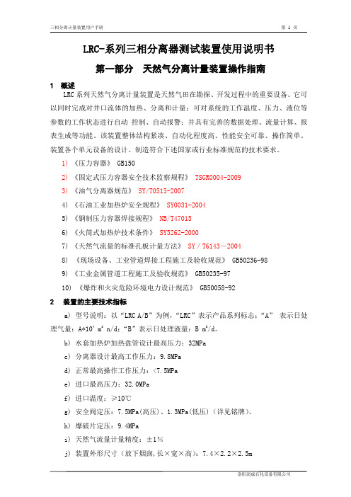
LRC-系列三相分离器测试装置使用说明书第一部分天然气分离计量装置操作指南1 概述LRC系列天然气分离计量装置是天然气田在勘探、开发过程中的重要设备。
它可以同时完成对井口流体的加热、分离和计量;可对系统的工作温度、压力、液位等参数的工作状态进行自动控制、自动报警;并具有完善的数据处理、流量计算、报表生成等功能。
该装置整体结构紧凑、自动化程度高、性能安全可靠、操作简单。
装置各个单元设备的设计、制造符合下述国家或行业标准规范的技术要求。
1)《压力容器》 GB1502)《固定式压力容器安全技术监察规程》 TSGR0004-20093)《油气分离器规范》SY/T0515-20074)《石油工业加热炉安全规程》SY0031-20045)《钢制压力容器焊接规程》NB/T470156)《火筒式加热炉技术条件》SY5262-20007)《天然气流量的标准孔板计量方法》SY/T6143-20048)《现场设备、工业管道焊接工程施工及验收规范》 GB50236-989)《工业金属管道工程施工及验收规范》 GB50235-9710)《爆炸和火灾危险环境电力设计规范》 GB50058-922装置的主要技术指标a)型号说明:以“LRC A/B”为例,“LRC”表示产品系列标志;“A”表示日处理气量:A*104 m3 n/d;“B”表示日处理液量:B m3/d。
b)水套加热炉加热盘管设计最高压力:32MPac)分离器设计最高工作压力:9.8MPad)正常最高操作工作压力:<7.5MPae)进口最高压力:32.0MPaf)进口温度:≥10℃g)安全阀定压:7.5MPa(高压)、1.3MPa(低压)(详见铭牌)。
h)爆破片定压:9.4MPai)天然气流量计量精度:±1%j)装置外形尺寸(放下烟囱,长×宽×高):7.4×2.2×2.5mk)供电电源:220VAC,10Al)装置出入口与外界管线的连接均为螺纹连接,口径如下:天然气入口:DN2 1/2”天然气出口:DN2 1/2”油和水出口:DN2 1/2”3 工作原理、主要设备及仪表天然气分离计量装置的工艺流程及主要设备见流程图1。
Crowcon 油气行业烟火和气体检测设备说明书

ApproachWith Crowcon’s expertise in detection equipment combined with over 40 years of experience in the oil and gas sector, their products offered distinct advantages for OMEGA. Whilst the basic function and operation of gas detection equipment is the same across all manufacturers, Crowcon’s products offered the highest specifications and levels of class compliance, with the added commercial benefits of a competitive price and a short delivery lead-time.These strong technological and commercial benefits meant that OMEGA decided to work exclusively with Crowcon as their supplier of gas detection equipment, sampling units and control panels. OMEGA now integrates Crowcon’s specialist gas detection equipment, with other third-party components such as smoke detectors and alarm systems, to provide customers with complete, turn-key fire and gas detection systems (Fig 1).The main control panel in OMEGA’s fire and gas detection system is Crowcon’s Gasmonitor.The signals from all of the detectors for gas, smoke and toxic gas hazards are sent to this control panel. In a typical installation, the control panel may receive signals from over 200 smoke detectors and over 80 manual call points, as well as from gas detectors located in various locations throughout the site.RequirementBudgets have to have limits, but there is one area in which cutting cost could mean cutting back on the protection provided for employees.In fire and gas detection, exposing employees to risk can be life-threatening but, as Crowcon was able to demonstrate to OMEGA Integration, it is not necessarily the most expensive detection systems that provide the highest specifications or levels of protection.A leading integrator of end-to-end systems, OMEGA Integration assembles and installs fire and gas detection and telecommunications systems in both off-shore and on-shore production sites. For OMEGA’s customers throughout Asia, quality and dependability are just as important as cost. “When we put our name to a system, we have to ensure that every element within it goes further than simply meeting the relevant class regulations.Each part must also meet the highest specification and build quality,” explains Gener Gonzalo Valencia, Manager, Projects & System Design from OMEGA Integration. “Previously,OMEGA has used equipment from some of the world’s largest manufacturers of fire and gas detection equipment, but high cost does not necessarily mean the highest specifications. This was particularly true of the equipment’s ability to operate in high-temperature applications. Our goal was to find a supplier who could match our knowledge of the Oil and Gas industry and provide fire and gas detection equipment with the highest specifications at a competitive price.”Omega IntegrationFire and gas detection and control systems in the oil and gas industry: cost versus value. Do higher costsalways mean higher specifications?Case StudyF i g 1: C r o w c o nG a s m o n i t o r c o n t r o l p a n e l i n t e g r a t e s i n t o fi r e a n d g a s d e t e c t i o n s y s t e m s“When we put our name to a system we have to ensure that every element within it goes further than simply meeting the relevant class regulations, each part must also meet the highest specification and build quality”The control panel also provides the operator with the flexibility to set alarm points and other status indicators according to each application. Gas detector alarm points can, for example, be set for the Lower Explosive Limit (LEL) ), and in parts per million (ppm) for toxic gases like, hydrogen sulphide (H 2S). The Crowcon Xgard gas detectors are used as they meet class compliance across a range of applications. OMEGA also specified Crowcon’s Air Sampling Units (ASU), which are typically placed in the intake ducts to the heating, ventilation and air-conditioning (HVAC) system, to provide earlydetection of the presence of both toxic and flammable gas. As the operation of Crowcon’s Gasmonitor control panel and Xgard detectors were already familiar to OMEGA’s service personnel, the drawings and documentation were already included in the working design, providing a seamless installation and training of personnel on site. In addition to the high specification and competitive cost,OMEGA also needed products which were easy to specify and to Gener, “I don’t want my engineers working through complex ordering guides every time they need to specify a product. Our response times are also improved when our engineers don’t have to chase suppliers for documents and drawings before they can be included in our submissions to customers. Crowcon’s standardised product selection process and easy access to technical documentation helps to improve both the productivity of my engineering teams and our customer service.” The combination of Crowcon’s high specifications and competitive pricing enables OMEGA to provide customers with equipment which combines the highest specifications with the highest value for money, as well as enabling installation on short lead-times.© 2019 Crowcon Detection Instruments Ltd. Copyright to some photographs held separately.。
燃油计量仪校准指南说明书

®The following procedure is suggested by our staff for conducting field meter tests. We have found it tobe an accurate and fast method for testing and calibrating meters.Step 1:(New or remanufactured meters) Slowly dispense several gallons of fuel through the meter before attaching it to the computer or pulser.The purpose of this step is to prevent damage to the computer or pulser. The meter will spin rapidly as the air in the lines is displaced by fluid. Run several 5 gallon drafts through the meter to completely purge it of air. Use the air bleed plug found on certain meters (older A.O. Smith, Gilbarco, and Southwest) to allow the air to escape. All air must be purged from the meter to obtain consistent results. (If the nozzle will reach the tank fill pipe, run 50 to 100 gallons through the meter.) This ensures that all meter parts are “broken in” and all air is purged. Meter parts will “take a set” if left in storage for a long time andmust be broken in again.Step 2:“Wet the can”by filling your test measure with fuel. Dump the fluid back into the tank until it stops flowing and starts to drip. Continue to drain, while counting to 10 seconds. This procedure leaves a very thin film of fluid on the inside of the can. By using a “wet can” and allowing a 10 second drain after each 5-gallon draft, you will be able to test the meter very accurately. The key is to consistently drain the test can the same way. Otherwise, the variation in thickness of the film of fluid will cause your results to vary by several cubic inches.Step 3:Run your first test after resetting the computer or electronic readout to zero. Fill the test measure at “fast flow”. The nozzle clip is on the highest flow notch. If the nozzle has no clip, hold it wide open. Observe whether there was a “computer jump” when the pump was activated. If there was a jump, your results will be invalid. Fill the can until you come to exactly 5 gallons on the computer or electronic readout.For electronic computers, each .001 of a gallon you run over or under 5,000 gallons represents .231 cubic inches of fluid. Hence, .004 gallons is approximately 1 cubic inch.For mechanical computers, it is essential to bring the gallon wheel back to the exact starting position. The width of the “0” line on the wheel is approximately equivalent to one cubic inch of fluid. One “trick of the trade” for mechanical computers is to set the price per gallon at $2.310 and observe the money readout. Since there are 231 cubic inches per gallon, 5 gallons would display $11.55 (5 x 2.31) on the money wheel. Each 1¢off from $11.55 is equivalent to 1 cubic inch in your test measure. If you failed to stop exactly at $11.55 (5.000 gallons), you will know how many cubic inches you ran over or under. Thereby, you will be able to make a more accurate meter adjustment and save time.Step 4:Observe the position of the fluid in the test can and adjust the meter in the direction that will bring it to the zero position. When reading the test can, it is important that you not introduce parallax into your observations. That is, your eyes should be level with the fluid level in the sight glass and the indicator line on the test can. The can must be level.Step 5:Run another 5-gallon “fast flow” test after draining the test measure and resetting the computer or readout. To obtain accurate results, it is important that the “fast flow” rate for the tests be as consistent as possible. Observe the results. Repeat Steps 3 - 5 until the meter is calibrated to the “zero” line within +/- 1 cubic inch.Step 6:Run a 5-gallon “slow flow” test after draining the test measure and resetting the computer or read-out. Set the nozzle clip to the lowest flow position. If the nozzle has no clip, test the device at 5 gallons per minute, or the minimum discharge rate marked on the device, whichever is less. Once again, this flow rate must be consistent for accurate results. Note: Most meters will over-deliver at very low flow rates.Step 7:Observe the test results.If the meter has been in service 30 days or less, National Institute of Standards and Technology (NIST) Handbook 44 allows a tolerance of +/- 3 cubic inches from “0” for both the fast and slow tests. If the unit has been in service longer than that, the allowable tolerance is doubled to +/-6 cubic inches. Metric tolerances are+/-50 milliliters from “0” in a 20 liter test for new or replaced meters and +/- 100 milliliters for older units.Bennett - 4000•To increase, move pin and turn lower dial counter-clockwise until the pin drops into an aligned hole. There is a tab on the lower dial to facilitate turning.•To decrease, move pin and turn lower dial clockwise.•Three holes equal approximately one cubic inch in a 5-gallon test measure.Bennett - SB-100Calibration - direction is marked on meter body•To increase, remove pin, turn calibration dial counter-clockwise, and replace pin.•To decrease, remove pin, turn calibration dial clockwise, and replace pin. •One hole equals approximately one cubic inch in a 5-gallon test measure.Use of the pin retainer on the opposite side of the dial allows adjustment by approximately one-half cubic inch.Gilbarco - Advantage, Highline, TrimlineCalibration - direction is marked on meter body.•To increase, remove pin, turn dial in counter-clockwise direction, and replace pin.Always complete the adjustment by turning the calibration mechanism ina clockwise direction.First turn it in a counter-clockwise direction past the point where youwant it and then back again.This takes out the clearance between the screw thread.•To decrease, remove pin, turn dial in clockwise direction, and replace pin.•One hole equals approximately one cubic inch in a 5-gallon test measure.Use of the bottom pin retainer allows adjustment by approximatelyone-half cubic inch.Gilbarco - Encore, Eclipse C+Calibration is performed electronically. There is no manual calibration adjustment mechanism on the meter. Refer to the dispenser operation manual for calibration instructions.LC / Liquid Controls - M5 (used in many high flow dispensers)•Loosen the screw on the collar that holds the adjuster thimble in place.•To increase, turn adjuster thimble to the left (unscrew).•To decrease, turn adjuster thimble to the right (screw in).The numbers shown horizontally on the thimble represent tenths of onepercent (0.001) of adjustment.This is equivalent to approximately one cubic inch in a 5-gallon test measure, or 23 cubic inches in a 100-gallon test measure.The smaller graduations between the numbers represent (0.0002) of adjustment.Each small graduation is equivalent to approximately 1/5th of one cubic inch in a 5-gallon test measure, or 41⁄2cubic inches in a 100-gallon test measure.The numbers shown on the upper portion of the adjuster (0 through 5)represent one percent of adjustment.Tighten the screw on the collar that holds the adjuster thimble securely.Schlumberger Centurion - SM100A / Tokheim 100•To increase, turn BOTH adjusting screws counter-clockwise.•To decrease, turn BOTH adjusting screws clockwise.Turning BOTH screws one “click” equals approximately one cubic inchin a 5-gallon test measure.NOTE: BOTH SCREWS MUST BE TURNED THE SAME NUMBER OF “CLICKS”. Southwest/Schlumberger - E-400•To increase, move pin clockwise and turn upper dial counter-clockwise until pin drops into an aligned hole.•To decrease, move pin counter-clockwise and turn upper dial clockwise until pin drops into an aligned hole.•Four holes equal approximately one cubic inch in a 5-gallon test measure. Tokheim•To increase, move pin and turn upper dial clockwise.•To decrease, move pin and turn upper dial counter-clockwise•Five holes equal approximately one cubic inch in a 5-gallon test measure.(continued)Universel Epsco / A.O. Smith•To increase, move pin and turn upper dial clockwise•To decrease, move pin and turn upper dial counter-clockwise•One hole equals approximately one cubic inch in a 5-gallon test measure. Wayne - 2PM 4,5,6•To increase, lift and rotate the adjustment knob in clockwise direction.•To decrease, lift and rotate the adjustment knob in counter-clockwise direction.•One notch equals approximately one cubic inch in a 5-gallon test measure. Wayne iMeterCalibration is performed electronically. There is no manual calibration adjustment mechanism on the meter. Refer to the dispenser operation manual for calibration instructions.Meter Calibration GuideAll manufacturers’numbers, names, trade names, trademarks and descriptions used here are for reference purpose only. None of the rebuilt items listed here are the products of the identified manufacturers.®PMP CORPORATIONP .O. Box 422 • 25 Security Drive • Avon, Connecticut 06001860-677-9656 • Toll Free 800-243-6628 • Toll Free Fax 888-674-0196Email:******************•Website:Form 116-1005Printed on recycled paper©2005 PMP CORPORATIONNotes。
油气测试仪安全操作及保养规程
油气测试仪安全操作及保养规程油气测试仪是用于测量油气的温度、压力和流量等性能指标的仪器设备。
它在石油、化工、航空、军工等领域具有广泛的应用。
在使用油气测试仪的过程中,合理的操作和保养不仅能够延长使用寿命,还可以保证设备的稳定性和安全性。
本文将介绍油气测试仪的安全操作及保养规程。
安全操作规程1. 设备检查在使用油气测试仪之前,必须对设备进行检查,以确保设备状态正常、安全。
具体操作如下:•检查设备的电缆、管路和连接部分是否紧固牢固。
•检查设备的外观和内部连通管道是否完好无损,是否有漏气、漏油、漏液现象。
•检查压力表或流量仪表的读数是否正常,是否需要校准。
2. 技能要求使用油气测试仪需要具备一定的专业技能和经验,以下是相关技能要求:•必须具备相关技能的专业人员操作;未经过专业培训的人员不得随意操作设备。
•操作人员必须具备相关知识,了解设备的工作原理和优化原理,熟练掌握相关技术参数,能够判断仪器数据的准确性和合理性。
3. 操作要求在使用油气测试仪进行测量时,应严格按照以下操作规程进行操作:•在进行操作前必须熟练掌握说明书,并按规程操作。
•在从系统中取样时,必须使用正确的取样管和阀门,避免样品污染。
•在接口处要注意舒适连接,以保证测量的精度和准确性。
•启动设备前必须先静态检查,在充分了解设备状态并确保处于正常工作状态后,方可进行启动操作。
•在操作过程中,要注意记录数据。
记录必须按要求进行,包括记录测量数据、必要的信息和备注。
4. 安全要求在油气测试仪使用过程中,必须严格遵守安全要求:•操作人员必须穿戴工作服、工作鞋或靴子、安全帽等安全防护装备,规定操作时必须戴防护手套、护目镜、口罩、头盔等特定安全防护用品,以保障人身的安全。
•操作人员对化学液体、瓦斯、氢气等特种气体必须先了解其危害性以及预防措施。
•对于燃气管道等易燃易爆区域内操作,必须有两人以上在场,必要时可以设置警戒标志或者警戒区域。
•在进行设备操作时,要避免产生火花和静电,避免产生爆炸等安全事故。
智能油井计量仪

智能油井计量仪用户手册四川省科学城久利电子有限责任公司重要提示仪器利用前请仔细阅读本用户手册, 以便充分了解仪器性能,正确利用仪器。
用户欲了解产品规格及技术指标的其它情况,请直接与本公司市场部联系。
本用户手册内容会有更新,欲了解最新版本请与本公司市场部联系。
本用户手册发布日期:2013年12月目录1 ........................................................................................适用范围- 4 -2..........................................................................................工作原理- 4 -3.................................................................. 产品型号及表示方式- 4 -4 仪器介绍.................................................................. -5 -简介................................ - 5 -仪器的量程.......................... - 6 -5.技术性能.................................................................. - 6 -智能油井计量仪技术性能 .............. - 6 -仪器正常工作的必要条件 .............. - 8 -5.2.1流量范围......................... - 8 -5.2.2结蜡和利用寿命................... - 8 -5.2.3气、液比......................... - 8 -6.智能油井计量仪利用方式 ......................................... - 8 -井口固定装置 ........................ - 9 -6.1.1简介............................. - 9 -6.1.2接线方式......................... - 9 -井口数据录取器 ...................... - 9 -6.2.1井口数据录取器简介.............. - 10 -6.2.2井口数据录取器利用方式.......... - 10 -7.井口数据读取器..................................................... - 14 -井口数据读取器简介 ................. - 14 -井口数据读取器现场收集数据操作步骤.. - 15 -井口数据读取器回放操作步骤:(与计算机连接)- 16 -8 软件利用指南 ........................................................ - 16 -概述............................... - 16 -安装............................... - 17 -软件运行的初始设置 ................. - 17 -井口数据录取简易操作(笔记本方式).. - 18 -数据处置软件的利用 ................. - 19 -8.5.1 回放数据..................... - 19 -8.5.2 打开数据....................... - 20 -8.5.3数据处置窗口.................... - 21 -8.5.4 数据分析软件的利用 ............. - 26 -8.5.5常规设置和功能................. - 27 -8.5.6软件利用常见错误及处置方式:.... - 30 -9 配置清单................................................................ - 32 -10安装要求 .............................................................. - 33 -11联系方式 .............................................................. - 36 -1适用范围本说明书适用的范围是智能油井计量仪系列产品。
输油站计量设备操作规程(3篇)

第1篇一、前言为确保输油站计量设备的正常运行,提高计量数据的准确性和可靠性,保障油品输送的安全生产,特制定本操作规程。
本规程适用于输油站内所有计量设备的操作和管理。
二、计量设备操作前的准备工作1. 操作人员应熟悉本规程,了解计量设备的性能、操作方法及注意事项。
2. 操作人员需通过专业培训,取得相应的操作资格证书。
3. 操作前,应对计量设备进行检查,确保设备完好、功能正常。
4. 检查设备电源、仪表、传感器、通讯接口等是否正常。
5. 检查设备清洁度,确保无污垢、油渍等杂质。
6. 检查设备运行参数,如温度、压力、流量等,确保在正常范围内。
三、计量设备操作流程1. 启动设备(1)打开设备电源,检查设备运行状态。
(2)启动设备,观察仪表显示,确认设备正常运行。
2. 设备校准(1)根据设备类型,选择合适的校准方法。
(2)按照校准步骤,对设备进行校准。
(3)校准完成后,记录校准数据,并存档。
3. 计量操作(1)根据输送油品类型,选择合适的计量器具。
(2)将计量器具与设备连接,确保连接牢固。
(3)启动输送设备,开始计量操作。
(4)观察仪表显示,确保计量数据准确。
4. 数据记录与处理(1)记录计量数据,包括时间、油品类型、流量、温度、压力等。
(2)对数据进行整理、分析,确保数据准确可靠。
(3)对异常数据进行调查、分析,找出原因,采取措施。
5. 设备停机(1)停止输送设备,关闭计量器具。
(2)关闭设备电源,确保设备安全。
四、计量设备操作注意事项1. 操作人员应严格遵守操作规程,确保设备安全运行。
2. 操作过程中,注意观察设备运行状态,发现异常情况立即停机检查。
3. 严禁操作人员擅自拆卸、改装设备。
4. 操作人员应定期对设备进行维护保养,确保设备性能良好。
5. 计量数据应准确、可靠,如有疑问,应及时上报相关部门。
6. 操作人员应掌握设备操作技能,提高操作水平。
五、计量设备操作人员职责1. 负责设备的日常操作、维护保养。
- 1、下载文档前请自行甄别文档内容的完整性,平台不提供额外的编辑、内容补充、找答案等附加服务。
- 2、"仅部分预览"的文档,不可在线预览部分如存在完整性等问题,可反馈申请退款(可完整预览的文档不适用该条件!)。
- 3、如文档侵犯您的权益,请联系客服反馈,我们会尽快为您处理(人工客服工作时间:9:00-18:30)。
多井式油气计量装置
一、概 述
圆 形 多 井 式 油 气 计 量 装 置 ,是 对 传 统 油 气 计 量 工 艺 的 改 进 。与 传 统工艺相比具有一套计量装置对多井油气自动计量功能、占地面积 小 、操 作 方 便 、无 人 值 守 、撬 装 化 的 优 点 ,能 根 据 用 户 需 要 ,实 现 单 井 油 气 量 自 动 远 传 与 报 警 。适 合 应 用 于 海 洋 平 台 、人 工 岛 、偏 远 区 块 或老油田自动化改造,是传统油气计量的理想换代产品。
经济——紧凑的设计降低了安装费用。 手动或自动的操作满足了您确切的需要。 灵活——同时可连接 8 条流水线——可有 8 个输入口。 大的生产室,设计用来防止砂或石蜡的积累。 比其它竞争的产品有较小的密封表面,减少了泄露的机会。 操作简单——转子很容易通过扳手或执行器转动以选择合适 的流水线。 体由高强度球墨铸铁或铸钢制成。
─3─
多井式油气计量装置
可使阀门置位于相对应的位置。 与阀门的连接:
1、通电使执行器转至 1#位置。 2、同样使阀门转至 1#位置。 3、 将 支 架 固 定 的 阀 门 上 。 4、 用 联 轴 器 和 螺 钉 将 阀 门 芯 轴 和 执 行 器 的 输 出 轴 固 定 。 5、 拧 上 执 行 器 和 支 架 间 的 螺 钉 。 6、转动执行器确定无偏心、倾斜、运行平衡、注意不 要逆方向 运行。 ( 3) 旋 转 式 分 配 阀 门 对于可靠性和低维护费用来说简便的旋转式分配阀在支管装置 操 作 中 给 你 带 来 最 大 简 便 。例 如 ,在 七 钻 井 联 结 装 置 中 ,这 种 1 只 通 用的阀门至少可以代替 14 只普通的阀门…并且去除了在老式联管箱 中 所 看 到 的 阀 门 、管 道 及 配 件 等 的 复 杂 混 乱 。这 种 旋 转 式 分 配 阀 可 以 连接达 8 条流水线——当其它流水线的油气继续流过正常的生产系 统 时 ,它 可 隔 开 其 中 任 何 一 条 输 入 流 水 线 用 于 计 量 、测 试 或 取 样 。这 种特性
图3
图4
-7-
多井式油气计量装置
3.半自动测量 按“ ”画面跳至(图 5)
图5
(井号及时间设定相同与手动)
4.自动测量按“
”画面跳至(图 6)
图6
选择井号及时间按“ ”键弹出画面(图 7)选好井号时间按“
回自动画面按“
”就开始按顺序开始测量。
”返
图7
-8-
多井式油气计量装置
5.设置画面 按“ ”键进入设置面(图 8),在这页可以设置每个井号的各种 参数,选择你要设的井号点按进出弹出设置页(图 9)
1 切断阀 油气分离中心
6 放空阀 4 球阀
放空池
a、正常流程:先将 2 多回转中心阀回至 0 号位,再将管道上的 1 截止止回
阀打开至行程线位置,再将 3 球阀打开即可。
b、计量流程:1 截止止回阀打开至行程线位置,再将 2 多回转中心阀用手
动或自动旋至测量的井号对位好,打开分离中心的 1、2 切断阀,开启 PLC 自动 计量中心,输入所要设定的计量时间,(设定方法:在 PLC 操作与电脑控制系统 操作有详细说明)。
分干线数量
15 50 5~ 15
25 65 5~ 15
32 80 5~ 15
40 100 5~ 11
50 150 5~ 11
65 200 5~ 11
2. 公称压力:PN1.6MPa~PN4.0MPa 3 .适 用 介 质 : 油 、 含 油 污 水 、 水 、 蒸 汽 4 .介 质 温 度 : 20º~ +80º 5.供电电源:220V 50Hz 300W 6.压力损失:在最大流量时不超过 0.3Mpa 7 .压 力 范 围 及 精 度 : 0Mpa~~4.0Mpa, ±1% 8.单井流量范围及精度:2m³/d~~720 m³/d,±3% 注:订货须注明防爆要求。
20) 测试输出口
名称 八通 分配器
工作压力 (磅)/平方英
寸 1000
旋转式分配阀用的分度扳手
输入口 尺寸
2 英寸
输入口 数量
6
测试 输出口
2 英寸
排出口 尺寸
4 英寸
重量 (磅)
162
5
材料 球墨铸铁/ 铸钢
规格参数表:
机
型
项目
电源
输出力矩 动作范围 动作时间 保护装置 环境温度 额定电流 绝缘电阻
─4─
多井式油气计量装置
所有耐磨聚四氟乙烯的配件保证长的使用寿命,无需润滑维 护。滑动的擦拭动作可清洁配合表面—比垂直座动作要强的多。
维修保养简单方便。
适合于高温和硫化氢运行操作。
( 5) 分 配 阀 主 要 零 件 及 规 格 参 数
1) 转子驱动方轴
装孔
-6-
多井式油气计量装置 自动控制操作说明
九、PLC 文本操作说明:
1.打开电源人机显示(图 1)这一个有六个功能可选。可以选手动测量、半
自动测量、自动测量、设置参数、查看测量数、风机开关等。
2.手动测量、 按“
图1
”键画面跳至(图 2)。
图2
井号选择按“ ”弹出画面(图 3)时间选择按“ ”键弹出画面(图 4)
c、放空流程:先关闭抽油机(关闭切断阀),将来油切断,然后将 1 截止
止回阀关闭,再将备用通道阀打开,打开放空阀,将流程中剩油放尽,放空完成。
d、备用流程:在多回转中心阀出现阻塞或出现其它损坏现象,而需要维修,在
不影响正常生产的情况下,将流程导至 5 备用中心,关闭截止止回阀、放空阀、 3 球阀,将 4 球阀与备用通道阀打开,完成流程导通, 注:在多回转中心阀在维修完毕,应导回正常流程或计量流程。
五、流程原理图
分 管
2 进
球阀
进 球阀
分 管 1 进
球阀
5 进
分 管
多通道圆形分配器
总管出
球阀
进 3 管 分
球阀
球阀 中 心 分 管
分 管
4 进
油气计量器
球阀
─2─
多井式油气计量装置
六、使用与操作
1.该 系 统 可 以 水 平 放 置 安 装 在 管 道 的 任 何 位 置 。 2.安 装 时 介 质 流 向 应 与 阀 门 壳 体 上 的 流 向 标 志 保 持 一 致 。 3.当 管 道 焊 接 作 业 时 要 避 免 阀 门 过 热 ,防 止 烧 坏 调 节 阀 的 橡 胶 密 封件 4.使 用 压 力 不 得 超 过 额 定 压 力 。
三、型号编制示例
XDY 5 -- - -- -
阀体材料代号(Z 铸钢 B 不锈钢) 公称压力 分干线公称口径 连 接 代 号 (I 焊接连接 II 法兰连接 III 卡箍连接) 分干线数量 产品代号
─1─
多井式油气计量装置
四、技术指标
1.公称通径:
分干线 公称通径 DN ㎜ 总干线出口)公称
通径 DN ㎜
图8
图9
6. 查看画面 按“
”进入画面(图 10)按你要查看的井号进入这个井的
最后测的七次参数(图 11)
七、旋转式分配阀和执行器
①标度盘及 8 个微动开并的外壳,每个孔一个。开并调节方便, 用于进行适当的阀孔定位。
② 带 活 动 端 子 板 的 接 线 盒 ,用 于 快 速 方 便 地 连 接 程 序 装 置( 控 制 ) 面板。
③90 瓦,220 伏特,单相,950 转/分。 ④指示器,用于显示哪个井在测试。
耐压值 手动操作
限位 防水性 安装角度 位置测量 驱动电机 箱体材料 盖子材料 进线接口
重量
CH-40
AC200/220V, 50/60Hz 400N • M 0~3600 150 秒 过热保护 -300 ~600 0.8A
100MΩ /DC500V AC1500V 1 分钟 同附带手柄操作 电气、机械八重限位
5) 顶部聚四氟乙稀电动机轴套
6) 毡密封
7) 转子“0”型密封圈
8) 盖板“0”型圈
9) 弹簧适配器调节螺母
10) 转子“0”型密封圈
11) 测试输入口
12) 流水线输入口
13) 波状调节弹簧
14) 转子密封固定件
15) 聚四氟乙烯转子密封
16) 转子体
17) 阀体
18) 转子“0”型密封圈
19) 生产输出口
相当于 IP-65 可任意角度安装 可选装开关或电位计
90W 压铸铝合金 压铸铝合金 PE1/2″Y 进线线锁
8.1kg
─5─
多井式油气计量装 八、多井式分配阀组操作说明:
多井分配阀组
2 多回转中心阀
1 截止止回阀
3 球阀
出口
2 切断阀
切断阀
4 球阀
5 备用及放空中心 球阀
备用通道阀
##
过滤器
进口
在 泛 滥 采 集 操 作 中 尤 其 重 要 ,因 为 它 能 提 供 自 动 获 得 有 利 于 控 制 泛 滥 的频繁单井测试的经济可行的方法。
旋 转 式 分 配 阀 是 那 么 的 适 合 自 动 化 ,以 至 于 您 如 今 可 以 安 装 一 开 始 用 扳 手 手 动 操 作 的 系 统 ,而 且 以 后 它 可 以 随 地 进 行 自 动 操 纵 且 不 需 任何的附加费用,这点不同于那些一开始就要求自动操纵的系统。 ( 4) 分 配 阀 的 优 点 :
-XDY 多井式油气计量装置
使用说明书
浙江金龙自控设备有限公司
ISO9001:2000 ZHEJIANG JINLONG YROMCONTROL EQUIPMENTS CO.LTD