自动门控制器用户指南
电动门控制器的调试设置手册
电动门控制器的调试设置手册1. 概述电动门在现代建筑中的应用越来越广泛,它不仅提高了出入口的便利性,还增加了安全性。
电动门控制器作为电动门的核心部件,起着控制门体运行和保护系统的重要作用。
本手册旨在介绍电动门控制器的调试设置方法,以确保电动门正常运行并满足各项要求。
2. 前期准备在进行电动门控制器的调试设置之前,需要做以下准备工作:2.1 确认电源稳定电动门控制器需要稳定的电源供应,因此在调试设置之前,需要确保电源电压稳定,并使用合适的电源线进行连接。
2.2 安装确认确保电动门控制器和其他相关设备已正确安装和连接,并检查是否存在松动、断开或损坏的情况。
必要时进行维修或更换。
2.3 了解控制器功能在调试设置之前,了解电动门控制器的各项功能和参数设置非常重要。
查阅产品说明书,熟悉控制器的工作原理和各个功能的作用,为后续调试设置做好准备。
3. 调试设置步骤3.1 电动门开门速度的调试3.1.1 进入设置模式根据电动门控制器的不同型号和品牌,通过按下设定键或者特定的组合键进入设置模式。
在进入设置模式之前,请确保门体已完全关闭。
3.1.2 调整开门速度参数在设置模式下,通过调整开门速度参数的数值,来改变电动门的开门速度。
根据实际需求,逐步调整参数数值,直至达到所需的开门速度。
3.1.3 保存设置在完成开门速度的调试后,确保将设置保存。
方法通常是按下确认键或将设置参数写入存储器中。
3.1.4 进行试运行在保存设置后,进行电动门的试运行,观察门体的开门速度是否符合要求。
如有需要,可再次进入设置模式进行微调。
3.2 电动门关闭时间的调试3.2.1 进入设置模式类似地,通过按下设定键或特定组合键进入设置模式。
请确保门体处于完全关闭状态。
3.2.2 调整关闭时间参数在设置模式下,找到与关闭时间相关的参数,根据实际需要调整参数数值。
可以通过增加或减少参数数值来改变电动门的关闭时间。
3.2.3 保存设置确保将调试后的关闭时间参数保存,避免重新调试时需要重复操作。
3.2版本说明书(盖泽自动门说明书)

V3.2 Service menu V3.2版本调试说明书操作盒按键说明1. Service button 隐藏键2. Position unknown 门体位置未知指示灯3. Lights up for maintenance 待维护指示灯4. Lights up for reduced opening width 半开指示灯Display Operating mode Service mode显示 工作模式按键 调试模式按键nA Night 锁门键 X Cancel and return to first menu level 取消并返回第一栏Ls Shop closing time单向键 Confirm 确认键Au Automatic自动键 Scroll up Increase value 上翻键,数值增加do Permanently open常开键 Scroll down Decrease value下翻键,数值减少Simultaneously Change Summer (full opening width) Winter (reduced opening width)上翻键和下翻键同时按下,可以改变常开和半开模式。
Service button (1) + simultaneously Operating mode/Service mode switch隐藏键和确认键同时按下,可以进入或者退出调试模式。
Service button (1) + simultaneously. Lock/Unlock the DPS.隐藏键和常开键同时按下,可以将操作盒上锁或者解锁.Service button (1) + simultaneously .Remote control matching.(optional)隐藏键和锁门键同时按下,可以进行遥控器匹配.(选装)Press the service button and at the same time, the production test begins:隐藏键和自动键同时按下,可以对外部设备进行预先检测:P1 Lock unlocked.锁未上锁P3 Motor turns approx. 20 cm in one direction and then approx. 20 cm in the other direction.门体朝一个方向运行20cm,然后反方向运行20cm.P2 Lock locked.锁已上锁P6 Check for whether or not a battery is connected.检查是否电池没有连接.A0 Battery was not detected.未检测到电池.A1 Battery was detected. 检测到电池.If a battery is connected, it must be detected. Only the presence of the battery is determined,not whether it is sufficiently charged.如果电池连接到控制器,无论电池是否在充满状态,电池一定会被检测到存在.If a fault occurs during the production test, the test is aborted and the fault displayed.如果预先检测有故障,错误代码会显示在操作盒上.Unplug the battery after the production test and leave it unplugged until commissioning.预先检测结束后,如果不进入学习状态,请将电池插头拔出.Learn controller.进入学习状态Learning of the drive is started with the LE display by pressing the input button ( ).如果操作盒没有显示LE,请按确认键 ,直到显示LE.CAUTION: The leaves accelerate quickly when the leaf mass is being determined! Step out of the sliding path.注意:学习过程中,门扇会快速运行一次来检测门扇重量.请保持通道没有阻碍.The door leaves open and close several times. The controller determines the following parameters:门扇会来回开关数次.操作盒会显示如下代码:L0 Start learning 开始学习L1 Testing the rotary transducer 检测编码器L3 Opening width, closing position 检测通道宽度,关闭位置L2 Toothed-belt lock 皮带锁检测L8 Friction 阻力检测L4 Leaf mass 门扇重量检测L6 Reduced opening width 半开宽度确认The leaves stop with L6. Push leaves into the desired reduced opening width by hand and confirm ( ).门扇停在通道中间.用手推至需要的半开宽度,按确认键储存半开位置.Automatic acceptance of the current position occurs after 20 sec.如果20秒内不确认半开宽度,系统将默认目前所在位置为半开位置.L7 End learning 完成学习.Confirm to save the determined values ( ).按确认键保存学习资料.If an error occurs, learning is cancelled with the EL message.如果有故障,学习无法完成,显示ELDisplay error with Er, remedy cause and restart learning.进入调试模式,在Er菜单中寻找故障原因,解除故障后重新学习.The operating mode Au is switched to automatically after the learning of a brand-new controller.学习完成后会显示Au,进入自动工作模式Check the running behaviour of the door and adjust other parameters if necessary.检查门体运行状况,根据需要进入调试菜单进行参数调节.Switch to Service mode and check whether all connected assembly groups and safety systems were learnt in menu item di. 进入调试模式,在di菜单下查看外部设备是否储存到控制器中Clear oE fault memory.在oE 菜单下清楚以前的故障信息Service menu 调试菜单1st MenuDisplay显示Description调节内容 Setting values调节参数uO Opening speed开门速度调节03 04…10 12…20 25 …5080 cm/sec厘米/秒.*).uC Closing speed关门速度调节 03 04…10 12…2025 …50 80 cm/sec厘米/秒.*).SO Latching action open开门终止位速度调节 00 01...07 cm/sec.厘米/秒SC Latching action close关门终止位速度调节 00 01...07 cm/sec.厘米/秒oH Summer hold-open time全开门保持开启延时调节00 01...10 12...20 25...60 sec./秒or Winter hold-open time (reduced opening width)半开门保持开启延时调节00 01...10 12...20 25...60 sec./秒oS Authorized contact hold-open time授权开关开门保持开启延时调节00 01...10 12...20 25...60 sec./秒.od Dynamic extension of the hold-open time 动态保持开启时间确认 00 No否01 Yes是Bo Acceleration加速度调节 1...10 12...20 25...40 × 10 cm/s2 *)厘米/秒(Multiply displayed value by 10)(实际数值为显示数值乘以10)*) The maximal speed and the accelerationdepend on the door weight and on thefriction.最大运行速度和加速度根据门体的重量和摩擦力而变化。
智能锁控制器的用户手册

智能锁控制器的用户手册智能锁控制器用户手册1. 前言感谢您购买我们的智能锁控制器。
本用户手册旨在为您详细介绍智能锁控制器的安装、配置和使用方法,以便您能够充分发挥智能锁的功能,提升家居安全和便利性。
2. 产品介绍2.1 规格参数在此列出智能锁控制器的详细规格参数,包括尺寸、重量、电源要求等,以便您对产品有个整体的了解。
2.2 主要功能特点详细介绍智能锁控制器的主要功能特点,例如远程开锁、密码管理、指纹识别等,以及支持的通信协议和配套APP等信息。
3. 安装准备在开始安装智能锁控制器之前,您需要做以下准备工作:3.1 安全须知提醒用户在安装过程中注意安全事项,如避免触电、避免在高温或潮湿环境下安装等。
3.2 所需工具和材料列出安装过程中需要使用的工具和材料清单,例如螺丝刀、螺丝、电池等。
4. 安装步骤4.1 安装位置选择根据您的实际需求,选择智能锁控制器的安装位置,可以是门框、墙壁或其他合适的位置。
4.2 固定安装底座将安装底座固定在选择的安装位置上,确保底座牢固、平稳。
4.3 连接线缆和电源将智能锁控制器与底座上的线缆连接好,并将合适的电源接入。
5. 配置与使用5.1 初始设置首次使用智能锁控制器前,您需要进行一些初始设置,例如设定管理员密码、添加用户指纹等。
5.2 远程控制介绍如何通过配套APP或其他方式实现远程开锁、监控门锁状态等功能。
5.3 密码管理指导用户如何管理和更改密码,以及如何分配不同权限的用户密码。
5.4 指纹识别详细说明如何添加和管理用户指纹信息,以及如何确保指纹识别的准确性和安全性。
6. 常见问题解答在此部分,我们解答智能锁控制器的常见问题和疑惑,帮助用户更好地理解和使用产品。
7. 安全提示提醒用户在使用智能锁控制器时注意安全事项,例如不共享密码、定期更换电池等,以确保家庭安全。
8. 保养与维护介绍智能锁控制器的保养与维护方法,包括定期清洁、更换电池等,以保证产品的正常运行和寿命。
电动门遥控使用说明

3.上班开门时,需先开楼道西侧玻璃门,进入室内将电动门右侧插棍锁取出方可使用电动门。然后用遥控按B键解锁即可正常使用。
进入室内将电动门右侧插棍锁取出方可使用电动门
电动门遥控使用说明
电动门遥控使用说明
A键:按A键是锁定,指纹、门内开关键停止工作,只有用遥控器才能打开电动门
B键:按B键是关门,同时也是解(按A键后锁定)锁键
C键:按C键是开门
注:
1.每天下班时首先用遥控关上门后,按A键锁定门外指纹开关,门内开关及内红外线开关。
DO3000X门机操作流程说明

DO3000X门机操作流程说明1. 概述DO3000X门机是一种用于自动门开关操作的设备。
本文档旨在提供DO3000X门机的操作流程说明,以便用户正确且安全地操作设备。
2. 操作步骤以下是DO3000X门机的操作步骤:步骤一:开机准备1. 确保设备已连接电源,并打开门机的电源开关。
2. 检查设备的各个部件是否正常运作,如门机的传感器、按钮等。
如发现异常情况,请及时报修。
步骤二:设置运行模式1. 根据实际需求,选择门机的运行模式,如自动模式、手动模式等。
可根据设备安装位置和使用场景进行选择。
2. 进入设置菜单,调整相关参数,如延迟时间、敏感度等。
步骤三:开启门机1. 确保门机没有障碍物阻挡,以确保安全运行。
2. 按下合适的按钮或触摸屏,开启门机。
3. 若选择自动模式,则门机会根据设定的参数自动开关。
若选择手动模式,则需要用户手动操作门机。
步骤四:监控门机运行1. 在门机运行期间,用户可以通过监控界面进行实时监测。
2. 如发现异常情况(如异常噪音、门无法正常关闭等),请立即停止门机运行,并联系维修人员处理。
步骤五:关闭门机1. 当门机运行完成或不再需要使用时,请按下相应的按钮或触摸屏,将门机关闭。
2. 等待门机完全停止运行后,方可离开设备附近。
3. 安全事项在操作DO3000X门机时,请注意以下安全事项:1. 请勿将手指或其他物体伸入门机的运行区域,以免造成伤害。
2. 请勿长时间连续操作门机,以免设备过热。
3. 若发现设备有异响或异常温度,请立即停止使用,并联系维修人员检查。
4. 严禁未经授权人员进行维修和改装设备,以免引发安全事故。
请用户在操作DO3000X门机之前,仔细阅读并理解本文档中的操作流程说明和安全事项。
如果有任何疑问,请联系相关技术人员进行咨询。
以上为DO3000X门机的操作流程说明,感谢使用DO3000X门机!。
长风自动门说明书

长风自动门说明书一、产品概述长风自动门是一种智能化的门控产品,采用先进的技术和高质量的材料制造而成。
它具有打开和关闭门的自动功能,能够根据用户的需要进行灵活的设置和调整。
长风自动门广泛适用于商业建筑、公共场所、住宅小区等场所,为用户提供便捷、安全、舒适的出入口环境。
二、产品特点1.智能感应:长风自动门配备了先进的感应器,能够根据人员位置和距离自动感知并打开门,无需手动操作。
2.安全保护:长风自动门具有多重安全保护功能,包括紧急停止、防撞保护和防夹保护等,以保障用户的安全。
3.静音设计:长风自动门采用特殊的设计和材料,具有良好的降噪效果,保证用户在使用过程中不会受到噪音的干扰。
4.节能环保:长风自动门采用高效的能源管理技术,具有低功耗和高能效的特点,为用户提供节能环保的使用体验。
5.操作简便:长风自动门配备了直观的人机界面,使用简单易懂的操作方式,方便用户进行设置和调整。
三、使用方法1.安装:请参考长风自动门安装手册,按照要求进行正确的安装。
安装完成后,请仔细检查各个部件是否安装牢固,确保门的运行安全。
2.开关电源:将长风自动门连接到电源,并打开电源开关。
此时,屏幕上会显示相应的开机画面。
3.设置参数:按照长风自动门操作手册的指引,进行系统参数的设置。
包括开门速度、感应距离等参数。
根据实际需要,进行相应的调整。
4.试运行:完成参数设置后,关闭门,然后手动推开门,观察是否能够正确感应到人员并打开门。
若有异常情况,请重新调整参数,直到正常运行。
5.日常使用:长风自动门在正常运行状态下,能够自动感应并打开门,用户只需轻推门即可进入。
在离开时,门会自动关闭。
如遇到特殊情况,用户可通过手动按钮来进行打开和关闭门的操作。
四、注意事项1.请勿在门上进行攀爬或悬挂重物,以免影响门的正常运行。
2.在使用长风自动门时,应保持门周围的通道畅通,避免杂物阻碍感应器的正常工作。
4.请勿将长风自动门暴露在阳光、雨雪等恶劣天气中。
洛克莱智能门匯控制器用戶操作指南说明书
4P/N 190–112486 REV BAfter installing your receiver and transmitter, check the operation of your radio controls by moving approximately 45 feet back from the garage door, then press the transmitter button. Operation at this distance should be reliable. However, environmental conditions and the location of the transmitter and receiver will affect distance.• If the transmitter doesn’t activate the operator checkthe coding on both the transmitter and receiver. The code setting must match exactly . This may necessi-tate a reprogramming of the transmitter and receiver. • If the distance is inadequate check the battery and replace if necessary.• To maximize the operating distance move thetransmitter to different locations in the car until a satisfactory distance is achieved. Vanity mirrors on sun visors will affect performance.• If the receiver is in the proximity of a metal beam orother obstruction it may be necessary to relocate the receiver to increase the operating range. • If multiple receivers are mounted closer than 15 feet, blocking and interference may occur. Move the receivers further apart.• If system does not work at any distance, check that the receiver terminals are connected to the proper operator terminals.• If the HomeLink® transmitter does not activate theoperator or distance is inadequate,verify proper operation using the hand-held transmitter. Contact your HomeLink® system provider for help with configuring the HomeLink® transmitter and to resolve distance problems when using the HomeLink® system.Operational CheckIndustry Canada. Operation is subject to the following two conditions: (1) This device may not cause harmful interference, and (2) this device must accept any interference received,LINEAR LIMITED WARRANTYThis product is warranted to the consumer against defects in material andworkmanship for one year from the date of purchase. This warranty applies to first retail buyers of new devices. Warrantor will repair, or at its option, replace, any device it finds that requires service under this warranty, and will return the repaired or replaced device to the consumer at the warrantor’s cost. For warrant service and shipping instructions contact warrantor at the address shown below. Devices must be sent to warrantor for service at owner’s expense. The remedies provided by this warranty are exclusive. Implied warranties under state law are to the one year period of this written warranty. Some states do not allow limitations on how long an implied warranty lasts, so the above limitation may not apply to you. In order to be protected by this warranty, save your proof of purchase and send copy with equipment should repair be required. This warranty gives you specific legal rights, and you may also have other rights which vary from state to state.For warranty service and shipping instructions contact Linear at the phone number shown below. In order to be protected by this warranty, save your proof ofpurchase and send a copy with equipment should repair be required. All products returned for warranty service require a Return Product Authorization Number (RPA#). Contact Linear Technical Services at 1-800-421-1587 for an RPA# and other important details.MVP Radio Controls are compatible with HomeLink ®. Homelink ® is a registered trade mark of JohnsonControls, Inc.Garage Door and Gate Operator Radio ControlsMVP Receiver and TransmittersProduct FeaturesThese controls are designed to remotely operate garage door and gate openers. The MVP receiver is compatible with Classic, MVP and Original Allstar, Allister and Pulsar type dip-switch transmitters. The MVP receiver is available in one and three-door versions and may be used as shown below.The radio frequency of the remote controls is fixed and tuned at the factory. RF adjustments are not required and should not be attempted by the end user. There are no user serviceable parts in the radio controls.Installation StepsFirst, determine the type of operator (with or without receiver power). Refer to the operator manual or contact the operator manufacturer as needed. Next, attach the receiver to the operator according to the appropriate installation instructions. Next, set thetransmitter codes according to the instructions provided with the transmitter. To finish, program the receiver with the transmitter codes.Installation on Operator WithoutPower for ReceiversSome operators do not provide power for an external receiver. An optional transformer kit is required. Disconnect power to the operator before installing receiver. Connect the red and white wires of the receiver to the transformer. Connect black wires on the receiver to theterminals on the operator.Receiver WiringThe receiver provides one set of normallyopen isolated contacts (2 black wires). The red and white wires provide 24 VAC or DC power to the receiver.To wire, connect the white wire to ground or common and red wire to 24 VAC or DC. Next connect the black wires to the pushbutton circuit you wish to control.If the receiver is connected to a 3-terminal system, connect the red and white wires to power, connect either black wires to ground or common and the other to the pushbutton.USA & Canada(800) 421-1587 & (800) 392-0123(760) 438-7000Toll Free FAX (800) 468-1340。
布商 B901 门禁控制器系统用户指南说明书
Intrusion Alarm Systems - B901 Door ControllerB901Door Controlleru Direct interface to compatible Wiegand cardreadersu On-board buzzer output and supervised on-board pointsu Request to Exit and Request to Enter inputs thatcan have a shunt only optionu Four door states: Locked, Unlocked, Secured,Fire Unlocku SDI2 support as well as SDI compatibleThe B901 Access Control Interface Module is a fullysupervised, addressable SDI/SDI2 bus device thatallows access control integration for Boschcompatible control panels. This module offers 14programmable levels of access authority. Authority foraccess is controlled by the user level, the group of theuser, the time of day, the door state, and the areaarmed state. Control each authority restrictionthrough automatic and manual functions.A door that has been automatically released by thecontrol panel will require manually re-engaging toreturn to normal.In a combination Fire/Intrusion system, the B901should not be used to lock doors used for emergencyegress unless these doors have a mechanical releasemechanism.FunctionsReader input•Standard 5-wire Weigand interface.•+5 VDC or +12 VDC supplied to power readers.•Open collector output for reader LED.Unsupervised inputs•Tamper. Supports normally open devices.•REX. Supports normally open devices. Request toExit (REX) on short.•RTE. Supports normally open devices. Request toEnter (RTE) on short.Supervised input• 1 kΩ End-of-line resistor.•Use for door contact.Door statesFour door states are controlled through the keypad,RPS (Remote Programming Software), scheduledevents (SKEDs), and automatic programmablefunctions in the door controller parameters:•Locked. The lock relay can be deactivated (doorallowed to open) with a valid credential or REX/RTEinput.•Unlocked. The Lock relay is held in the deactivatedstate to allow access without the need of acredential.•Secured. The lock relay is activated and no accessis allowed even with valid credential (overridden byFire Unlock).•Fire Unlock. The lock relay is held in the deactivatedstate during a Fire Alarm. This allows free access toand from the building during an emergency.Two automatic functions link the door state to thearming state of the area:•Auto Door. When the area is Off (disarmed), thedoor state is switched to “Unlocked”.•Disarm on Open. With this function as "Yes," a userwith valid access rights activates the strike andturns off (disarms) the system after the door isopened. With this function as "No," the area turnsoff (disarms) upon the strike activation.Indicators•Heartbeat LED. Blue LED blinks on and off whensystem is operational. A rapid three-blink sequenceindicates a system error.•Reader LED. Rapidly blinking LED indicates theCard data is being received. When the LED is off, no card data is being received.Regulatory informationInstallation/configuration notesThe B901 Access Control Interface Module isindividually programmed through the control panel.The module is compatible with several credential models and readers.iNoticeNot all products and features are available in all regions. Consult your local Bosch representative for availability details.CompatibilityParts includedTechnical specifications Environmental considerationsPropertiesPower requirementsWiringCredentialsOrdering informationB901 Door ControllerFully supervised, addressable SDI2/SDI bus device that allows access control integration for Bosch G and B Series Control Panels.Order number B901 | F.01U.323.803ServicesEWE-DCTRM-IW 12 mths wrty ext door control module 12 months warranty extensionOrder number EWE-DCTRM-IW | F.01U.352.288Represented by:Europe, Middle East, Africa:Germany:North America:Asia-Pacific:Bosch Security Systems B.V.P.O. Box 800025600 JB Eindhoven, The Netherlands Phone: + 31 40 2577 284/xc/en/contact/ Bosch Sicherheitssysteme GmbHRobert-Bosch-Ring 585630 GrasbrunnTel.: +49 (0)89 6290 0Fax:+49 (0)89 6290 1020****************************Bosch Security Systems, LLC130 Perinton ParkwayFairport, New York, 14450, USAPhone: +1 800 289 0096Fax: +1 585 223 9180*******************.comRobert Bosch (SEA) Pte Ltd, Security Systems11 Bishan Street 21Singapore 573943Phone: +65 6571 2808Fax: +65 6571 2699/xc/en/contact/Data subject to change without notice | 202304171719 | V31 | April 17, 2023© Bosch Security Systems 2023。
欧科感应门控制器说明书
欧科感应门控制器说明书
1、有一个开关可以调试的,顺时针快,逆时针变慢,自己手动
调试就可以了。
2、放大电路增益调整,这个旋钮的位置在放大电路原件周围。
这个旋钮一般情况下不要调整,它被用于生产厂家校正微波模块灵敏度输出的离散性。
增益调整旋钮与灵敏度调整旋钮相比,增益调整旋钮不如灵敏度旋钮操作起来那么容易。
3、可以通过调整微波模块的俯仰、水平角度调整感应器的作用
区域。
4、灵敏度旋钮调整,通过调整MCU数模转换门限值确定灵敏度
的高低。
不同版本的感应器其位置不同,详见随机说明书。
5、其中灵敏度和微波天线仰角调整是比较简洁直观的方法,同
时注意调整天线角度的时候务必要断电后进行,有些松下自动欧科感应门感应器损坏就是因为在调整天线仰角的时候碰触到了电子线路
板部分造成短路,进而烧坏电子元件而损坏。
6、自动欧科感应门灵敏度旋钮的调整:通过调整mcu数模转换
门限值确定灵敏度的高低。
通过调整自动欧科感应门微波模块的俯仰、水平角度调整感应器的作用区域。
自动门用户手册
4
1
4
1
4
1
4
1
ห้องสมุดไป่ตู้
4
同 步 带张 力调整
同步带 张力 调 整
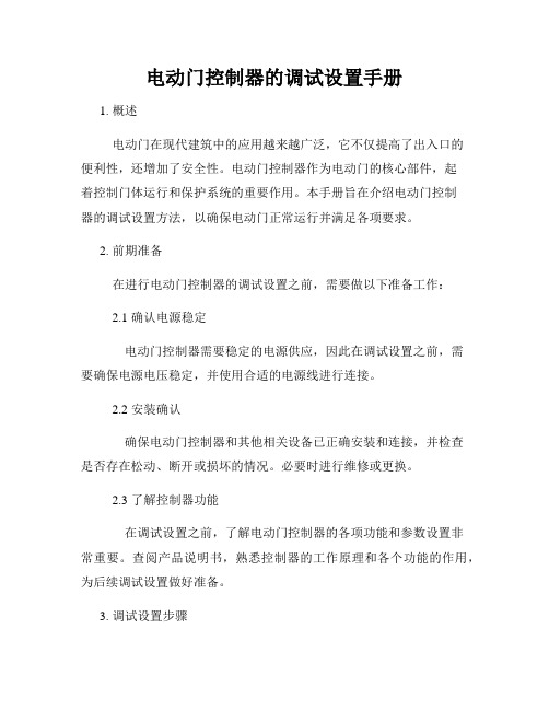
1. 左右 吊 架 应 直 线 安 装 在 门 扇 上 2. 将门 扇 悬 吊 在 动力 梁 导 轨 上 后 , 如 门 扇 向 左 或向右滑动,则说明动力梁没有 水 平 对 准 , 此 时 , 应 卸 下 门 扇 , 调 整 动 力 梁 位 置,使之呈水平状态 3. 门扇 悬 吊 在 导 轨 上 时 , 应 能 用 手 轻 轻 打 开 或 关 上 4. 活动 门 扇 应 垂 直 悬 吊 ※当 活 动 门 扇 与 固 定 门 扇 之 间 的 缝 隙 上 下 不 一致时,可拧松并调整吊架或地 轮 的 螺 栓 位 置(底 板 上 有 长 槽), 且 使 缝 隙 大小符合规定要求。 ※ 当 活 动 门 扇 如 右 图 所 示 倾 斜 不 正 时 , 可 调 整吊架部件的高度调整螺栓使之 垂直 5. 活动 门 扇 和 动 力 梁 、 盖 板 、 固 定 门 扇 及 地 坪 等静止物应无磨擦现象。
1. 拧松 吊 架 固 定 螺 栓( A )和 防 脱 固 定 螺 栓( B ) 2. 旋转 内 六 角 螺 栓( C ) ? ?至 要 求 标 准 高 ( 低 ) 度位置 ◆顺时针方向旋转门体升高 ?逆 时 针 方 向 旋 转 门 体 降 低 3. 拧 紧 吊 架 固 定 螺 栓( A ) 4. 最 后 调 整 防 脱 固 定 螺 栓( B )与 导 轨 底 平 面 的 要求标准(间隙0.5mm)
- 1、下载文档前请自行甄别文档内容的完整性,平台不提供额外的编辑、内容补充、找答案等附加服务。
- 2、"仅部分预览"的文档,不可在线预览部分如存在完整性等问题,可反馈申请退款(可完整预览的文档不适用该条件!)。
- 3、如文档侵犯您的权益,请联系客服反馈,我们会尽快为您处理(人工客服工作时间:9:00-18:30)。
自动门控制器用户指南
自动门控制器用户指南
1.引言
1.1 目的
本用户指南的目的是为了帮助使用自动门控制器的用户正确安装、操作和维护设备。
本指南将详细介绍自动门控制器的功能、操作步骤和常见问题解答,以确保用户能够充分利用该设备的各种特性。
1.2 范围
本用户指南适用于所有型号的自动门控制器。
在阅读本文档之前,请确保已经详细了解您所使用的自动门控制器型号。
2.产品概述
2.1 产品特性
自动门控制器是一款用于控制自动门的电子设备。
其主要特性包括:
- 可编程的开关时间间隔
- 灵活的开门和关门方式设置
- 多种安全功能,如红外线传感器和反向保护
2.2 产品组成
自动门控制器由以下组件组成:
- 控制面板:用于设置和调整自动门的参数和功能。
- 传感器:用于检测门的开关状态和环境条件。
- 电源供应器:为自动门控制器供电。
3.安装步骤
3.1 准备工作
在安装自动门控制器之前,请确保已完成以下准备工作:- 确保所有必要的工具和设备已准备就绪。
- 关闭门的电源,并确保门处于关闭状态。
- 阅读安装手册并按照其中的指示进行操作。
3.2 安装控制面板
按照以下步骤安装控制面板:
1.找到合适的安装位置,确保控制面板与门的位置相对应。
2.使用螺丝刀固定控制面板,确保稳固安装。
3.连接控制面板与电源供应器,确保电源连接正确。
3.3 安装传感器
根据自动门的类型和要求,安装相应的传感器。
一般来说,传感器应安装在以下位置:
- 红外线传感器:将其安装在门的两侧,确保覆盖门的整个开闭范围。
- 反向保护传感器:将其安装在门的下方,确保能够及时检测到障碍物并关闭门。
4.操作指南
4.1 基本操作
使用自动门控制器进行基本操作,请按照以下步骤进行:
1.按下电源按钮,确保控制面板已经启动。
2.调整开关时间间隔,可以通过控制面板上的菜单进行设置。
3.设置开门和关门方式,可以选择触发按钮、红外线传感器或定时器来进行设置。
4.2 安全功能
自动门控制器配备了多种安全功能,以确保用户和门的安全。
以下是一些常见的安全功能:
- 红外线传感器:当有物体或人员进入红外线传感器范围时,门会自动打开。
- 反向保护:如果门在关闭过程中检测到障碍物,门将自动停止并打开。
5.常见问题解答
以下是一些常见问题的解答:
1.问:控制面板没有反应。
答:请检查是否已正确连接电源供应器和控制面板。
同时,确保电源供应器的开关已打开。
2.问:红外线传感器无法正常工作。
答:请确保红外线传感器是否被遮挡。
如果被遮挡,请清除遮挡物。
6.附件
本文档涉及以下附件:
- 安装手册:详细介绍自动门控制器的安装步骤和注意事项。
- 规格说明书:列出自动门控制器的技术规格和性能参数。
7.法律名词及注释
本文档中涉及的法律名词及其注释如下:
- 无。