E+H超声波物位计FMU860HART英文操作手册
E+H料位计

48
22
8. 2 功 能 "仪表 地址" ( 06 0 ), 只用 于PR OFI BUS PA 4 8
23
8. 3 功 能 "前置 符个 数" (0 6 1), 只用 于H ART
49
8. 4 功 能 "ID号" ( 061 ),只 用于PR O FIB U S P A
49
2 4 8. 5 功 能 "输出 下限" ( 06 2 ),只 用于HAR T
58
3
9. 2 功 能 "记 录 曲线" (0E2 ) 9. 3 功 能 "包 络 线显 示" (0 E3 )
1 0 功 能 组"显示" (09)
10 . 1 功 能 "语 言" (09 2 ) 10 . 2 功 能 "返 回 初 始画 面" (0 93) 10 . 3 功 能 "显 示 格 式" (09 4) 10 . 4 功 能 "小 数 位 数" (09 5) 10 . 5 功 能 "小 数 点 符号" ( 09 6 ) 10 . 6 功 能 "显 示 器 测试 " (09 7 )
58 1 2 功 能 组"系 统 参 数" ( 0 C )
70
5 9 12 . 1 功 能 "位 号" (0C 0 )
70
12 . 2 功 能 "设 备标 签" (0 C 0), 只用 于F F
70
6 1 12 . 3 功 能 "行 规版 本" (0 C 1), 只用 于P ROF IBU S P A 7 0
E+H仪表设置指南

所有仪表上,按E可进入菜单,按+、-可在菜单中移动,+和-一起按可以退出到上级菜单。
1、CPM253 pH计:按E进入菜单,此时仪表需要输入密码(密码为22),按+,直到表上显示22,按E确认,仪表上显示,多次按-直到仪表显示CURRENT OUTPUT,按E进入,多次按E,直到表上显示,此时按+或-修改4mA对应的数值(如想改为0.00,则按-,修改为0.00);修改完以后,按E键确认,屏幕上显示,此时按+或-修改20mA对应的数值(如想改为14.00,则按+,修改为14.00),按E键确认即可。
此时,同时多次按+和-退出到初始界面。
2、FMU40、41、42、43、44 液位计:该图中,E为仪表探头到罐底的高度,F为设计图纸上的量程值(20mA对应的值)。
如图,按E进入basic setup,表上显示tank shape,多次按E,直到表上显示empty calibration,此时可以按+修改里面的数值,这个数就是上图说的E(即仪表探头道罐底的高度),如图,比如现在高度是5m,则按+,此时里的2会改变,修改为5后,按E确认,仪表自动跳到下一位,按+使这位显示小数点就可以,再一直按E确认就可以了。
改完empty calibration选项后,按E进入full calibration,这项里面可以修改仪表的量程(数据表上有)。
按E确认,一直按E直到显示同时按+和-退出到初始界面即可。
3、FMU130、131、230、231、232 液位计:上图的仪表的显示器。
该界面为V0H2,该界面为V3H2,即显示器右上角显示的内容。
按V键可以改变V的数值,比如现在为V3H2,按E后可进入V4H2,同样,按H键可以改变H的数值。
走到V0H1修改从探头到罐底的高度值,走到V0H2修改量程值(数据表上有,就是20mA对应的数),走到V8H2修改单位,0代表m,1代表英寸,应选择0。
然后多次按V和按H回到V0H0(测量界面)即可。
E+H流量计说明书
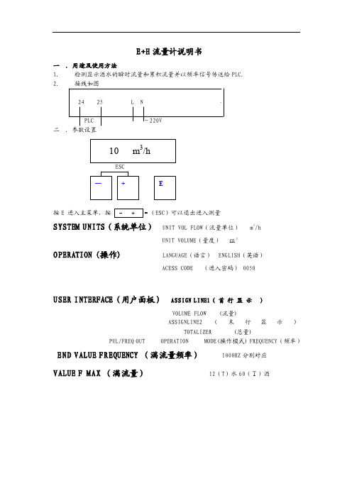
E+H 流量计说明书一 .用途及使用方法 1. 检测显示酒水的瞬时流量和累积流量并以频率信号传送给PLC. 2. 接线如图24 25 L NPLC ~220V 二 .参数设臵按E 进入主菜单,按ESC )可以退出进入测量SYSTEM UNITS (系统单位) UNIT VOL FLOW (流量单位) m 3/hUNIT VOLUME (量度) m3OPERATION (操作) LANGUAGE (语言) ENGLISH (英语)ACESS CODE (进入密码) 0050USER INTERFACE (用户面板) ASSIGN LINE1( 首 行 显 示 )VOLUME FLOW (流量)ASSIGNLINE2(末行显示)TOTALIZER (总量)PUL/FREQ OUT OPERATION MODE(操作模式) FREQUENCY (频率)END VALUE FREQUENCY (满流量频率) 1000HZ 分别对应 VALUE F MAX (满流量) 12(T )水60(T)酒二、安装1.安装位臵只有当满管时才能获得准确的测量,要避免以下安装位臵:(1)管道最高点(易聚积气泡);(2)直接向下的管线的敞开出口前;(3)泵的入口侧(防止抽压而造成的对流量管衬里的破坏);(4)有残渣聚积的场合和排水管的最低点(最好安装一个清洁阀)。
2.安装方位最适宜的方位可帮助避免气体的累积和测量管内的残渣存积。
垂直安装、流体自下而上的安装位臵为最佳方位。
若为水平安装,测量电极平面必须水平,这样可以防止由于夹带的气泡而产生的电极短时间绝缘。
空管检测功能仅当测量装臵为水平安装及变送器外壳向上时能正确工作。
3.振动如果振动剧烈,注意支撑管道和传感器;若振动非常剧烈应将传感器和变送器分开安装。
不允许利用外框承住传感器的重量,这会使外框变形并破坏内部励磁线圈。
4.出入口直管段安装传感器时要尽量避免阀门、三通、弯头等组件,与他们之间的距离应能保证所需的进口和出口直管段以确保测量精度:入口长度≥5DN,出口长度≥2DN。
超声波物位测量设备现场操作

可以到这里http://www.yhck88.com/进行帮助
用FieldCare操作
FieldCare是E+H公司基于 FDT标准的工 厂资产管理工具, FieldCare可以 对工厂中的全部 智 能设 备进 行组 态, 并且 支持用 户管 理这 些设 备。 通过 读取 这些 状态 信息 ,可 以方 便 并且有效地检查设备的应用情况。
支持以太网,HART,PROFIBUS,FF基金会现场总线等 可以·操作E+H生产的所有仪表 可以·操作支持FD T标准 的第 三方 设备,如 执行 器, I/O系统和传感器 确保·实现DTM设备的全部功能
·
用Commuwin II操作(基于通信协议HART或PROFIBUS-PA)
Commuwin II是用于智能变送器的具有图形支持(MS Windows)的操作软件,其通信协议 包括Rackbus,Rackbus RS-485,HART及PROFIBUS-PA。 Commuwin II支持以下功能: ·变送器的在线组态
加载、保存仪表数据(上传/下载) 测量·值与限位值的可视化 ·用记·录仪显示并记录测量值
Commuwin II无法显示包络线,需通过软件ToF Tool显示。
连接: HART带Commubox FXA191(可作附件) PRO·FIBUS-PA ·
用NI-FBUS设置软件操作(仅限于基金会现场总线)
·
测量系统满足EC-准则的法律要求。ENDRESS+HAUSER保证仪表已通过了所需 测试并贴有CE标志。
见“订购信息”。请注意相关的安全指南(XA)和控制或安装图(ZD)。
EN 60529
外壳保护级别(IP-代码)
超声波液位计操作手册
超声波液位计……………………………………………………………………保修政策:●用户在维修时请出示保修卡。
在保修期内因正常使用出现的故障,可凭保修卡享受规定的免费保修。
●保修期限:本公司产品保修期由验收日期起算十二个月内。
以下情况不在免费保修范围内:●产品或其部件已超出免费保修期。
●因使用环境不符合产品使用要求而导致的硬件故障。
●因不良的电源环境或异物进入设备所引起的故障或损坏。
●由于未能按使用操作手册上所写的使用方法和注意事项进行操作而造成的故障。
●由于不可抵抗力如:雷电、水火灾等自然因素而造成的故障。
擅自拆机修理或越权改装或滥用造成的故障或损坏。
限制说明:●请用户妥善保存保修卡作为保修凭证,遗失不补。
本保修卡解释权限归本公司所有,本公司有权对本卡内容进行修改,恕不事先通知。
7超声波液位计目录1概述 (1)2 技术指标 (1)3仪表安装 (2)3.1仪表外形尺寸 (2)3.2仪表接线 (2)3.3安装参数含义 (3)3.4仪表安装原则 (3)3.5安装注意事项 (4)4仪表调试 (4)4.1键盘说明 (4)4.2密码说明 (4)4.3 参数的设置 (4)4.3.1 液位标定(P01) (4)4.3.2 20mA设置(P02) (5)4.3.3显示模式设置(P03) (5)4.3.4探头高度(P04) (5)4.3.5反应速度设置(P05) (5)4.3.6 盲区设置(P06) (6)4.3.7 4~20mA测试设置(P09) (6)超声波液位计保修卡回执 (7)超声波液位计1、概述衷心感谢您选购本公司超声波液位计!本仪表包含多项专利技术,具有安全、清洁、精度高、寿命长、稳定可靠、安装维护方便等特点,适用酸、碱、盐、防腐、高温等各种领域。
本仪表可通过4~20mA或RS485(Modbus协议或其他定制协议)连接到显示表或各种DCS系统中,为工业的自动化运行,提供实时的液位数据。
本仪表具有如下特点:●电路设计从电源部分起就选用高质量的电源模块,元器件选择进口高稳定可靠的器件,完全可以替代同类型国外进口仪表。
FMU90超声波物位计简明操做说明

FMU90超声波物位计简明操做说明1、接线:如下图所示,注意,探头和电源的屏蔽线务必要接地。
2、操作:FMU90通常常见的几种调试通讯方式见上图。
最常见的调试方式:面板的调试方法:(操作面板各个部件功能介绍)a:参数名称;b:测量值,包含单位;c:显示标志;d:软件信息标志;e:操作信息指示灯;f:继电器状态指示灯;g:操作按键;按键组合:编辑参数时为退出菜单操作;(对当前的设定值不做保存)增加显示的对比度;减弱显示的对比度;锁定操作菜单;操作菜单矩阵说明:主菜单:(初次按下E键后,显示的各个操作矩阵的主菜单如下)L:初次使用需设定的菜单矩阵,(物位测量的操作信息)F:用于流量测量的操作信息;A:安全设定;R:继电器/控制;O:输出/换算;D:设备属性,标定显示和传感器管理;I:系统信息;S:服务;(只有在服务密码输入的情况下才是可用的)具体的操作见矩阵表:初次操作需要调整的几个参数:(见L菜单)测量的介质选择:固体(soild),液体liquid,默认介质为液体;见L菜单;空标值(empty calibration),也就是探头到池底、罐底的距离。
满标值(full calibration),20mA满量程对应的高度,一般情况为满标值减去30mm,具体设置过程参看上图矩阵表。
单位的设定方法:按E键进入主操作菜单后,按上下选择键选择device properties菜单(设备属性),然后按E键确定,再按上下选择键选择operating param(操作菜单)进入diistance unit(距离单位)选项,然后按上下键选择单位后按E键确认存储。
具体操作过程见上图。
其余参数在正常情况下不需要做调整。
各按键具体操作说明:见下图其他具体操作见矩阵表和英文操作手册(134-142页)。
超声波料位计使用说明书
注意:控制器直接暴露在阳光下,其运行温度可能会超过其指定的限制温度,并减少显示器的能见度。
建议:在阳光直射的场合,采用遮阳罩,避免仪器显示屏受到阳光直射,否则会减低仪器的使用寿命。
温馨提示:安装调试前,请仔细阅读用户手册!! YI2000W用户手册量程:0.45-8米额定电压: DC24V有限公司超声波料位计超声波料位计超声波料位计保修卡回执用户名称联系地址联系人联系电话产品型号产品编号验收日期安装负责人……………………………………………………………………超声波料位计保修卡说明产品型号产品编号验收日期安装负责人保修政策:●用户在维修时请出示保修卡。
在保修期内因正常使用出现的故障,可凭保修卡享受规定的免费保修。
●保修期限:本公司产品保修期由验收日期起算十二个月内。
以下情况不在免费保修范围内:●产品或其部件已超出免费保修期。
●因使用环境不符合产品使用要求而导致的硬件故障。
●因不良的电源环境或异物进入设备所引起的故障或损坏。
●由于未能按使用操作手册上所写的使用方法和注意事项进行操作而造成的故障。
●由于不可抵抗力如:雷电、水火灾等自然因素而造成的故障。
擅自拆机修理或越权改装或滥用造成的故障或损坏。
限制说明:●请用户妥善保存保修卡作为保修凭证,遗失不补。
本保修卡解释权限归本公司所有,本公司有权对本卡内容进行修改,恕不事先通知。
7超声波料位计目录1概述 (1)2 技术指标 (1)3仪表安装 (2)3.1仪表外形尺寸 (2)3.2仪表接线 (2)3.3安装参数含义 (3)3.4仪表安装原则 (3)3.5安装注意事项 (4)4仪表调试 (4)4.1键盘说明 (4)4.2 参数的设置 (4)4.2.1 料位标定 (4)4.2.2 20mA设置 (5)4.2.3探头高度 (5)4.2.4继电器参数设置 (5)4.2.5显示模式设置 (5)4.4.7 P--Multi菜单 (6)超声波料位计保修卡回执 (7)超声波料位计1、概述衷心感谢您选购本公司超声波料位计!本仪表包含多项专利技术,具有安全、清洁、精度高、寿命长、稳定可靠、安装维护方便等特点,适用酸、碱、盐、防腐、高温等各种领域。
超声波流量计操作手册说明书
MANUAL DE OPERACIÓN MEDIDOR ULTRASÓNICO2En cada tipo de instalación, los métodos de instalación de los medidores de agua varían de manera significativa.Antes de instalar el medidor es importante considerar que el espacio sea suficiente, no sólo para su ubicación, sino para colocar los otros elementos necesarios para realizar los procesos de mantenimiento y monitoreo del medidor de agua.Debe existir espacio en ambos lados para poder acceder a ellos de forma cómoda. En caso de los modelos de gran tamaño es probable que requieran un polipasto.Para el correcto funcionamiento, se requieren estar en un tramo recto con una longitud mínima determinada.Evitar vacío, colocando la válvula check aguas arriba.min. 5 x D Considerar mínimo 5 diámetros libres antes del medidor y 3 diámetros después.min. 3 x DMANUAL - MACROMEDIDORES MECÁNICOS3El punto de colocación debe asegurar que la sección se mantenga llena durante el uso.EMPAQUE EMPAQUETambién debe evitarse su exposición a altas temperaturas y vibraciones excesivas.Se recomienda utilizar empaques en la instalación del medidor.El sensor cuenta con una flecha que indica el sentido del caudal del fluido.Restricciones del medidorInstalar el medidor de manera correcta.Evitar que el medidor quede instalado en los puntos altos del sistema de tubería.Se recomienda no instalar el medidor en posición vertical.4MANUAL - MACROMEDIDORES MECÁNICOS 5No colocar el medidor con la caratula boca abajo, esto impide el funcionamiento correcto del equipo.Se recomienda no instalar el medidor en tuberías con inclinación.Antes y después del medidor de agua, colocar válvulas para cortar el suministro de agua si hay necesidad de desinstalación o reparación. Utilice válvulas de paso para cerrar comple-tamente la sección transversal de una tubería de agua.La tubería instalada debe tener una forma tal que no haya posibilidad de que se cree una bolsa de aire en el medidor de agua. El medidor debe permanecer completamente lleno de agua.El flujo de agua a través del medidor debe corresponder a la dirección de las flechas colo-cadas en ambos lados del cuerpo.SoportesEl medidor se debe instalar sin tensión mecánica (torsión, flexión). Si es necesario, instale soportes para las tuberías.6MANUAL - MACROMEDIDORES MECÁNICOS 7El medidor de flujo debe tener un montaje seguro sobre silletas a una altura adecuada.SILLETA DE SUJECIÓNSILLETA DE SUJECIÓNLas tuberías aguas arriba y abajo del medidor deben estar apoyadas de modo seguro, de modo que estas no causen tensiones al medidor. Es importante no colocar soportes debajo del medidor de agua. Para grandes diámetros, se pueden colocar los soportes debajo de las contrabridas.8Las caratulas de los medidores de agua están regulados bajo la norma NOM-012-SCFI y el diseño está orientado para facilitar la lectura del usuario. El sistema ofrece la lectura prin-cipal en metros cúbicos, para realizar la conversión a litros es necesario considerar que 1 metro cubico equivale a 1000 litros.Para realizar la lectura del medidor se tiene que ubicar en la caratula la lectura principal, así como los submúltiplos ubicados en forma de reloj, los cuales dependerán del tipo de medidor (desde 1 hasta 4 círculos). La lectura se debe tomar de la siguiente forma:1.- Tomar el dato de la escala principal, ejemplo 32.- El siguiente valor es el que indica el primer reloj marcado como x0.1, en este caso la aguja indica un valor entre 8 y 9 por consiguiente se toma el valor inferior siendo 8, el cual lo separaremos con un punto para indicar los decimales, ejemplo3.83.- Pasar al siguiente reloj y colocar el valor a un lado del último dato, ejemplo 3.87 y así sucesivamente hasta el último reloj indicador.4.- Este dato se encuentra en metros cúbicos para convertir a litros es necesario multipli-carlo por 1000 y el resultado estará en litros.3.873 m3 x 1000 = 3873 LitrosLectura del medidorIndicador de flujo:MANUAL - MACROMEDIDORES MECÁNICOS9Sensores de pulsos (Reed switch)ComunComunPulso 1Pulso 1Pulso 2Pulso 2Sensor de pulsos W Diagrama para los siguientes modelos: • WF NOM • IF • HWFSensor de pulsos U Diagrama para los siguientes modelos: • WF • -IF-• R20010El medidor de agua es un instrumento cuya capacidad de medición cambia con el tiempo. Además, el deterioro de esta capacidad es generalmente el resultado de la influencia agre-siva del agua, por lo que, después de un tiempo debe ser desinstalado de la red, para su mantenimiento y calibración.No utilice productos químicos de limpieza que tengan una influencia perjudicial sobre los materiales de los que están hechos los elementos del medidor de agua.Las reparaciones deben realizarse por personal autorizado en plantas de servicio. Consultar a su agente de ventas.Inspección, mantenimiento y reparaciónLos medidores de agua recibidos de entregas o desinstalados de la red deben almacenarse en un lugar cerrado, libre de vapores cáusticos, etc., que puedan tener un efecto destruc-tivo en el estado de los medidores de agua.La temperatura ambiente debe estar entre 5 y 30°C, y la humedad relativa del aire no debe de ser superior al 80%. Tanto durante el transporte como durante el almacenamiento, los aparatos deben estar protegidos de las vibraciones y, en particular, de los golpes que pue-dan dañar el cuerpo o los elementos internos.El transporte debe realizarse protegiendo el embalaje del fabricante o un embalaje susti-tuto, el cual resguarde totalmente el producto de daños.Almacenamiento y transporteResolución de pulsosMANUAL - MACROMEDIDORES MECÁNICOS 11• Es importante que los medidores se manejen con cuidado debido a sus piezas mecá-nicas, durante el transporte y previo a la instalación. En caso de los equipos de gran tamaño para uso industrial, que requieren el uso de un montacargas, se debe colgar la pieza en los enganches y moverlo en un ángulo de 45°.• No transporte el medidor usando un diablito de carga colocando el cuerpo con las bridas sobresaliendo del diablito. Esto podría abollar la carcasa o dañar los ensamblajes del sistema interno.• Transportar siempre el medidor con su embalaje original.Para limpiar la carcasa del instrumento y su pantalla, use únicamente un trapo suave ligera-mente humedecido con agua o un producto para la limpieza de cristales.Nunca use solventes fuertes, ya que pueden agrietar o remover la pintura de la carcasa e incluso destrozar las partes plásticas.Evite que los cables se doblen o sufran de torsiones y nunca haga nudos. Cuando vaya a conectar o desconectar el cable de alimentación del instrumento, siempre tómelos única-mente por los conectores.NotasCuidado del medidorManejo adecuado de los cables• Si el medidor no indica nada cuando el agua fluye, compruebe si el rotor no está atas-cado por algún sólido.• Si tiene problemas al conectar el sensor de pulsos, comuniquese con el departamento de soporte técnico de Equysis.• Si tiene algún problema con su medidor, no rompa los sellos de seguridad. Y envíe el equipo a Equysis para su diagnóstico.Problemas comunes。
E+H差压变送器操作说明书
Detlabar S FMD76/77/78, PMD70/75 差压变送器操作手册目录1、安全手册 (3)1.1 设计用途 (3)1.2 安装、调试和操作 (3)1.3 操作安全性 (3)1.4 安全惯例和图标的注释 (4)2、认证 (4)2.1 仪表设计 (4)2.2 供货范围 (5)2.3 CE标志 (6)2.4 注册商标 (6)3、安装 (6)3.1 接收和存储仪表 (6)3.2 安装条件 (7)3.3 安装手册 (7)3.4 安装后的检查 (12)4.接线 (12)4.1 仪表的接线 (12)4.2 电子腔室的接线 (13)4.3 等电势 (15)4.4 接线后检查 (15)5.操作 (16)5.1 现场显示模块(可选) (16)5.2 操作按钮 (17)5.3 现场操作-不带就地现场显示 (19)5.4 现场操作-带现场显示 (22)5.6 TOF TOOL操作程序 (25)5.7 通过HART手持终端操作 (25)5.8 Commuwin II操作程序 (25)5.9 锁定/解锁操作 (26)5.10 工厂设定(重置) (27)6 调试 (28)6.1 功能检测 (28)6.2 语言选择与测量模式选择 (28)6.3 位置调节 (29)6.5 液位模式 (32)6.6 差压测量 (36)7 维护 (39)7.1 表面清洁 (39)8.故障排除 (39)8.1 错误信息 (39)8.2 输出响应错误 (45)8.3 确认错误信息 (46)8.4 维修 (46)8.5 带防爆认证的仪表维修 (46)8.6 备件 (47)8.7 返修仪表 (47)8.8 存储 (48)8.9 软件 (48)9.技术数据 (49)10 附件 (49)10.1现场显示,TOF TOOL和现场手操器的操作菜单 (49)10.2 HART Commuwin II操作矩阵 (49)索引1、安全手册1.1 设计用途Detlabar S 是测量差压、流量和液位的差压变送器。
GF868超声波流量计说明书
GE Panametrics公司GF868通用超声波气体流量计简明使用手册概述1.以GE Panametrics公司提供的DigitalFlow®GF868英文手册《PragrammingManual》为准,中文简明手册仅供参考。
2.超声波时差法流量计使用一对传感器,每个传感器通过流体发射和接收超声波信号。
当流体流动时,顺流方向信号的传播时间短于逆流方向,这个时间差正比于流体流速。
DigitalFlow®GF868流量计测量这个时间差,结合设置的管径参数来计算流体的流速。
3.DigitalFlow®GF868系统包括GF868仪表部分,一对先进的超声气体传感器,前置放大器和测量管。
利用受专利保护的互相关时差技术(Correlation Transit-Time™),无压损,并具有极宽的量程比。
传感器安装和测量管路要求1.考虑到管路中流体可能存在的固体颗粒分布,传感器应水平安装。
2.选择测量管路时应该尽量避免选用流体自上向下流动的竖直管线。
1.传感器安装位置应远离弯头,变径,阀门,节流装置,安装点直管段的要求至少要满足前20D后10D(D为管线直径),如有阀门、泵、变径、节流装置等,直管段应适当再加长。
2.GF868传感器安装类别参见所附图(仅供参考)。
903 GF868的接线图参见所附图(仅供参考):开机注意事项●在GF868工作时不可带电插拔传感器接头●GF868上电前应接好传感器,以使内部的自动增益控制功能更好地发挥功效●每次连接传感器与GM868前应将传感器内储存静电放除快速启动流量测量本手册介绍了基本流量测量方法及下列描述:∙键盘功能描述∙编程∙测量显示∙测量值记录∙清除设定与记录∙校验∙常用的显示值∙故障诊断和排除此手册仅提供给用户快速使用流量计的一些简单步骤,它不包括详细的过程和程序的描述。
键盘功能描述DigitalFlow® GF868流量计共有39个键,每个键功能描述如下:编程要快速流量测量,DigitalFlow GM868流量计需要知道如传感器、管径壁厚、流体类型等参数,当将这些参数送入流量计后即可测量流量,同时可将这些参数以Site文件形式(现场参数文件)存储在流量计中以便今后测量时调用。
- 1、下载文档前请自行甄别文档内容的完整性,平台不提供额外的编辑、内容补充、找答案等附加服务。
- 2、"仅部分预览"的文档,不可在线预览部分如存在完整性等问题,可反馈申请退款(可完整预览的文档不适用该条件!)。
- 3、如文档侵犯您的权益,请联系客服反馈,我们会尽快为您处理(人工客服工作时间:9:00-18:30)。
Prosonic FMU 860...862
The Prosonic transmitter requires a serial interface. In this case a plug-in module allows the first current output to function as an interface for transmitting serial data along the 0/4...20 mA signal cabling. Units connected to the current output are totally unaffected by this digital signal. The plug-in module can be fitted at any time.
fields on that matrix line. • If a submenu is called up, then a value, data or a parameter can be shown or
entered in a matrix field.
Operating the Prosonic FMU using the HART handheld terminal
The DXR 275 Communicator can be used for operating the Prosonic FMU only if appropriate software is loaded in the handheld terminal. This software specifies the operating functions of the Prosonic and is known as the Device Description (DD).
The menu trees on Pages 6 to 8 show how to enter the matrix positions V and H to operate the menu for the Prosonic FMU 860...862 by using the HART Communicator.
Example: The matrix fields for the matrix line "Calibration Chan. 2" are not accessible for the one-channel mode of the FMU 862.
Entering the matrix position - selecting the menu
When ordering the handheld terminal, all transmitters are to be entered which are to be connected to the device. The Device Description can be loaded into the handheld terminal by Endress+Hauser at any time.
Note
3
Prosonic FMU 860...862
HART operation
"Communicator" menu
Detailed information on the "Communicator" menu is given in the operating manual provided with the handheld terminal. 1 Off-line The Communicator DXR 275 does not support this function. (Off-line enables calibration and editing of transmitter parameters and simulation of the instrument to be carried out off-line.) 2 On-line Supplies all main values and the input to the "Configure" menu. 3 Transfer The Communicator DXR 275 does not support this function. Transfer enables uploading of parameters from the transmitter to the Communicator as well as downloading in the reverse direction. 4 Frequency Device Not required for the Prosonic FMU. Refer to the operating manual for the Communicator DXR 275. 5 Utilities Enables the contrast to be adjusted on the display of the Communicator as well as activating the ’Auto-Polling’ function for the HART Multidrop mode. See the operating manual for the Communicator DXR 275.
1
Prosonic FMU 860...862
Language version
The HART Communicator is available in English.
HART operation
LCD
Menus
The Prosonic FMU has four menu levels: "Communicator" HART protocol "On-line" Main measured values and input for the "Configure" menu "Configure" Main menu for calling up a "Matrix line" "Matrix line" Submenu for "Configure" using matrix fields
BA 139F/00/e/01.95 Teile-Nr. 016490-1000 Communicator DXR 275 Firmware Revision 1.6 Module Revision 1.11
Prosonic with HART FMU 860...862 Ultrasonic Level Measurement
FMU862: .................
Online
1 >Value 1
60%
2 Value 2
60%
3 Configure
BACK
I O
0/4...20 mA
The handheld terminal is connected either locally to current output 1 (terminals 4 and 5) or in the control room at the communications resistor. Communications resistor in the measuring loop: 250 Ω < Rcom < 600 Ω. Length of cable: < 300 m, screened cable recommended, capacitance < 60 nF.
Note! The operating mode selected automatically makes available the appropriate matrix fields: Some fields are available for level measurement or flow measurement only. The positions of the fields can therefore move along the matrix line. These fields are indicated in matrix diagrams by a small black square.
"Communicator" menu
function keys
keys to select menu
keys to enter parameters
Universal HART Communicator DXR 275
"Online" menu
"Configure" menu
"Matrix line"
2
HART operation
Prosonic FMU 860...862
The "Configure" menu calls up the matrix:
• Each menu option in "Configure" indicates a matrix line: • If a menu option in "Configure" is called up, then a submenu appears with all matrix
HART operation
Endress +Hauser
Nothing beats know-how
HART operation
HART Protocol