Lumia800 拆机图解
利用Lumia 800 内置诊断模式
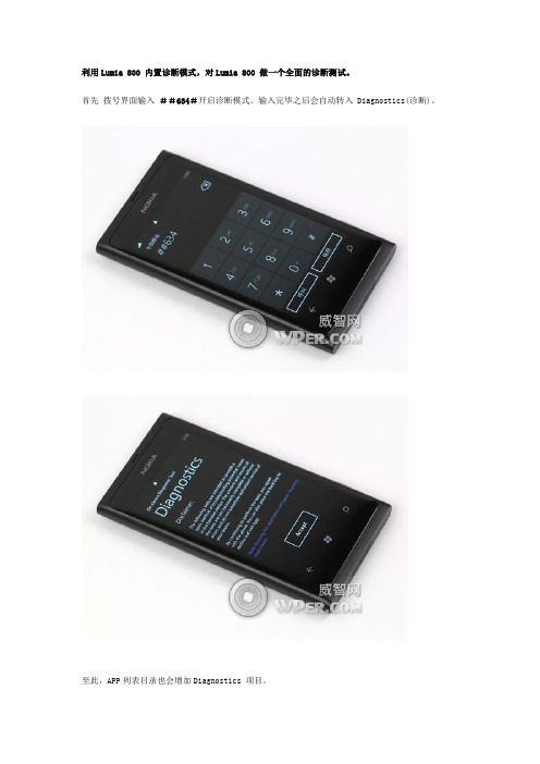
利用Lumia 800 内置诊断模式,对Lumia 800 做一个全面的诊断测试。
首先拨号界面输入##634#开启诊断模式。
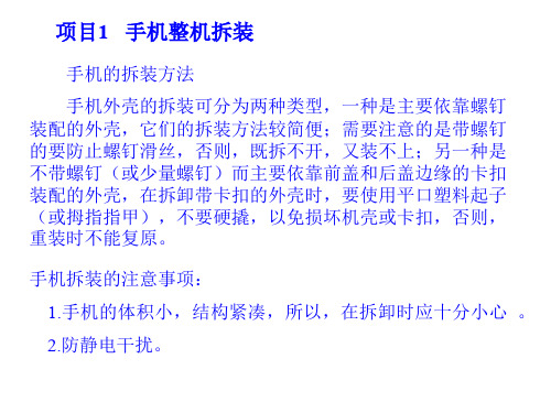
输入完毕之后会自动转入 Diagnostics(诊断)。
至此,APP列表目录也会增加Diagnostics 项目。
点击Accept 接受进入进入之后就是各项测试,我们先点击 Run All Test 运行全部测试。
每项测试完后都有一个评测,Pass 通过、Fail 失败。
第一项:LED屏的检测触摸屏幕分别显示白、黑、红、绿、蓝纯色屏,可以检测屏幕是否有坏点等。
第二项:Vibra 震动测试点击Start开启震动,Stop停止,Done完成。
第三项:Lights 灯光测试分别有屏幕背光和闪光灯的测试第四项:Auido Loopback 音频回送有听筒、耳机和扬声器的回送测试,对着麦克风说话即可。
第五项:Camera 相机测试拍照,接受即可。
第六项:按键测试按下边键,会有相对应的红色显示区域灭掉。
第七项:DTMF——dual-tone multifrequency 双音多频测试就是按键音的测试,两个音量强度。
第八项:Touch 手写测试第九项:Headset Detection 耳机测试插上耳机测试即可第十项:ALS 感光度测试可以在不同的光照强度下查看数值和亮度第十一项:Speaker Test 扬声器测试点击Play播放铃声第十二项:Proximity 接近测试物体接近屏幕显示Detected 检测到,这个测试指在测试接听电话时,靠近头部后关闭屏幕背光;远离头部,屏幕背光自动开启。
第十三项:Magnetometer 磁力仪指在测试定位的准确性第十四项:Power Source 电源测试显示电池供电及插电充电状态第十五项:Accelerometer 重力感应屏幕显示重力球,测试重力感应准确性总共十五项测试,最后界面显示测试通过状态。
绿灯表示Pass通过,红灯表示Fail未通过。
x200拆机图解(中文)

ThinkPad X200 and X200s 硬件维护手册/拆机手册关于本手册本手册适用于以下机型:ThinkPad X200MT 7454, 7455, 7457, 7458, 7459, 2023, and 2024ThinkPad X200sMT 7462, 7465, 7466, 7469, 7470, 2046, and 2047友情提醒:拆机有风险,动手需谨慎。
由拆机带来的风险和机器损坏,与本手册无关。
拆机“心得”:胆大心细:多研究,多实践。
别用暴力。
thinkpad的机器设计得很不错。
一般情况下如果你拆不开,要么是螺丝没下完,要么是卡扣卡太死。
多研究下,切忌使用蛮力!拆机之前:移除SIM卡部分x200和x200s用户使用x200/x200s进行3G上网以及GPS导航,在拆机之前,需要把SIM卡取下。
移除SIM卡的的操作手法如下图所示:(注意:移除SIM卡之前需要拆下电池,详见下一页“拆下电池”).注意断开连接ZIF排线,参考图示1.用指甲向上掰开固定扣2.自下向上取出排线1010 电池替换电池的重要提示:英文版里说了一堆。
简要翻译就是:1.尽量选用原装带FRU电池。
因为组装品牌电池可能没有经过完整测试。
(这个仁者见仁智者见智了)2.不要使用有物理破损或者已经知道有安全为题的电池。
3.外观破损的电池不在保修范围内。
游侠的提醒:请关机拆卸或更换电池。
带电很危险,可能会烧到机器。
购买电池需谨慎,目前市面上高仿电池横行,要提高警惕,注意鉴别。
危险请使用原装电池。
组装品牌电池可能自燃或爆炸。
电池移除步骤1.解开电池卡扣,按住电池卡口到解锁位置2.按图中所示方向移除电池当安装时:按照上图所谓反方向放入,确保卡扣扣好。
1020 硬盘进行该操作需要先行拆卸以下部件:v电池注意:v不要随手乱扔硬盘,万一砸到小朋友就不好了,没砸到小朋友,砸到花花草草也是不好的。
硬盘是很脆弱的,禁不起很大的震动,乱摇乱动会震坏损坏数据。
Nokia 5800 拆机图解 拆解手册

DISASSEMBLY INSTRUCTION1. Press to release the BATTERY COVER.2. Lift up and remove the BATTERY COVER.3. Unscrew the four TORX5+ screws.4. Release the snaps of the SIDE BAND ASSY with SRT-6.5. Do the same on the other side.6. Remove SIDE BAND ASSY.7. Use tweezers to remove SLIDE KEY. 8. Release the snap of the A-COVER in the bottomcorner as shown in the picture with SS-93 tool.9. Slide with SS-93 tool along the bottom side to release the snaps here as well. 10. Release the snap in the opposite corner of the bottom side.11. Go on releasing the snaps on both sides of thephone.12. Remove A-COVER.13. Rotate the TOUCH PANEL ASSY and TOUCH FRAME ASSY in the direction as shown. Be careful not to break off the flex.14. Use tweezers to remove KEYMAT .15. Carefully insert SS-195 display removal tool between LCD and LCD FRAME ASSY . 16. Lift up LCD on bottom side to detach it from the LCD FRAME ASSY .17. Move SS-195 tool underneath the LCD in thedirection as shown in the picture to lift up the LCD on top side of LCD FRAME ASSY .18. Rotate the LCD like the TOUCH PANEL ASSY and TOUCH FRAME ASSYin the direction as shown.19. Remove the two TORX 5+ screws.20. Rotate the PWB and the LCD FRAME ASSY in the direction as shown.21. Disconnect the PWB from the LCD FRAME ASSY .22. Open the connector on the top side to release the LCD FRAME ASSY .23. Open the flap.24. Pull the flex out.26. PWB can be taken away.25. Use SS-93 tool to disconnect the TOUCH FRAME ASSYand TOUCH PANEL ASSY.28. LCD can be taken away.27. LCD FRAME ASSY can be taken away. LCD FRAME ASSYhas always to be renewed.29. Remove CAMERA using SS-102 tool. 30. Detach the snap to lift up the EARPIECE with adental pick.31. Detach the UPPER FLEX ASSY in this direction. 32. Use a dental pick to detach the UPPER FLEX ASSY.34. Remove CONN CHR DIA 2.0mm with a DC-plug.33. Remove UPPER FLEX ASSY. UPPER FLEX ASSY hasalways to be renewed.35. Remove IHF SPEAKER with a dental pick. 36. Remove IHF FRONT GASKET if necessary.37. Remove the second IHF SPEAKER and IHF FRONT GASKET if necessary. 38. Separate the TOUCH PANEL ASSY from the TOUCH FRAME ASSY with SS-93 tool.39. TOUCH PANEL ASSY and TOUCH FRAME ASSY have always to be renewed.End of disassembling.11.ASSEMBLY HINTS1) Tighten the screws to the torque of 15 Ncm in the order shown. 2) Tighten the screws to the torque of 15 Ncm in the order shown.。
[教程]中兴U880拆机详细图文教程
![[教程]中兴U880拆机详细图文教程](https://img.taocdn.com/s3/m/db75ef4ef01dc281e53af0c9.png)
[教程]中兴U880拆机详细图文教程
中兴U880
中兴U880拆机?你试过木有?要怎么样拆机?拆机的方法何在?别急,现在就为你介绍下中兴U880拆机详细图文教程吧!拆机工具:
1.一把小号的十字螺丝刀
2.指甲(别告诉我你没指甲)红色的是螺丝,有个8个,蓝色的是卡扣总共有4个.8个螺丝卸下来后,就可以打开卡扣了,具体方法是:用指甲从白色边框这插入,关键是要对着卡扣位置,然后卡扣就会弹开。
4个都打开了后,就可以把黑色面板打开来了,就可以看到主板了。
电容屏驱动显示屏,SIM 天线,和喇叭是连在一起的,我就没再拆来了TF卡座,SIM 卡座连接板主板主芯片,CPU型号:MARVELL 88SV331xrev 0(v5l)
这是手机360测出来的,不知道准不准IC好多哦,这是在SIM卡这一面的感觉器开始装回去了第二装只装显示屏的开机电流机开好了,这是没有装SIM卡和触摸屏的亮屏电流,黑屏(待机)就没有试一步一步慢慢装回去整机电流,从按下开机键起,电流好像变化都不大,都在200到500MA之间黑屏(待机)电流,10MA,但很不稳定的,经常是10到300多这样跳,可能是后台在不停的检测信号吧机子又归原
样了,现在说说我拆机的原因了,就是圈圈里的这东西了好了,中兴U880拆机详细图文教程已贡献给大家了,想拆机的童鞋也可以来试一试哦!。
手机整机拆装
项目1 手机整机拆装
手机的拆装方法
手机外壳的拆装可分为两种类型,一种是主要依靠螺钉
装配的外壳,它们的拆装方法较简便;需要注意的是带螺钉
的要防止螺钉滑丝,否则,既拆不开,又装不上;另一种是
不带螺钉(或少量螺钉)而主要依靠前盖和后盖边缘的卡扣
装配的外壳,在拆卸带卡扣的外壳时,要使用平口塑料起子(或拇指指甲),不要硬撬,以免损坏机壳或卡扣,否则,
重装时不能复原。
手机拆装的注意事项:
1.手机的体积小,结构紧凑,所以,在拆卸时应十分小心。
2.防静电干扰。
3.显示屏为易损元件,要轻取轻放,不能用力过大和受压。
不要用热风吹显示屏,更不能用清洗液浸泡它,否则,屏幕将显示不正常。
4.养成良好的维修习惯,拆卸下的元器件要存放在专用元器
件盒内,以免丢失而不能复原手机。
5.折叠式、滑盖式和旋盖式手机都有磁控管类器件,换壳重
装时,不要遗忘小磁铁,以免磁控管失控,造成手机故障。
6.重装前板与主板无屏蔽罩的手机时,切莫遗忘安装挡板
(或绝缘纸),以免手机加电时,前后电路板上的元件短路,损坏手机。
7.记下拆机的先后顺序,否则,会出现装完手机后,剩下的
零件不知道装哪里。
8.重装机壳前,应先擦净液晶表面,装好机壳后,要用专用
清洁剂擦拭一遍机身,可以使手机光亮如新,重点是显示屏表面。
识别手机电路板。
小米手机拆机图文全攻略
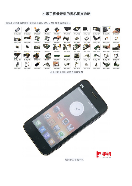
小米手机最详细的拆机图文攻略本次小米手机拆解照片分辨率全部为1024×768像素高清图片。
小米手机全部拆解图片的预览图待拆解的小米手机1.准备工作和拆机声明我们先来简单介绍一些拆机的准备工作与拆机原则,必要的工具是必须的,同时有一点需要网友明白的是,拆机有必须的拆机工具角塑料起子(即三角撬机片)一个、胆大心细的大脑一个。
拆下电池盖小米手机的固定螺丝都在机身内部,所以先要卸下电池盖和电池。
八个螺丝把电池盖和电池取下后可以看到八个螺丝,用十字改锥拧下,注意四角的螺丝与中间的四个螺丝大小不同,需要选用不同大小的改锥。
上图中橘黄色圆圈中标注了小米手机机身背部的八颗螺丝。
2.两截式螺丝引起我们注意印有小米LOGO的螺丝封贴掉即可看到螺丝,如果将此标签揭掉会失去保修。
依次去下所有螺丝依次卸下可以目测到的螺丝。
小米手机有一个边角上的螺丝很独特,它有两层螺帽,通过与机身对比可以发现原来这是一个挂绳孔,是一个很巧妙的设计。
用塑料起子打开主板保护壳拆卸保护盖注意边缘的卡扣把小米手机机身背部的八颗螺丝拧下还不能马上撬机身,通过上面的照片我们可以看到电池槽壁有一个卡扣,用螺丝刀把卡扣分离。
使用塑料起子将手机背壳滑开之后就可以使用塑料起子撬小米手机机身了,应该先从卡扣所处的那一边开始撬。
撬起之后沿着机身侧面滑动。
小米手机比一般的手机要好拆解,可以明显的看到卡扣,卡扣的力度也较小。
打开手机背壳小米手机机身边缘会有隐藏的卡扣,遇到卡扣时稍微用力撬动,但是应该注意力道,不要太过用力,否则会损坏机身,撬完一圈之后就可以把背盖拿掉了。
拆下背盖的小米手机先来看一下拆下背盖的小米手机,绿色的电路板已经暴露在我们眼前了。
手机背壳的背面来看一下小米手机背盖的背面(上图右),它并不是简单的塑料保护壳,我可以看到上面有很多的金属触点,左上角的多条黄色金属物就是耳机插孔的触点,合盖之后与电路板触点接通。
3.拆卸机身背壳扬声器我们暂时把机身放在一边,先来处理拆解下来的机身背壳,它并不是一个简单的保护塑料,在上面安装有扬声器等周边元件。
nokia e5拆机图解教程
矿产资源开发利用方案编写内容要求及审查大纲
矿产资源开发利用方案编写内容要求及《矿产资源开发利用方案》审查大纲一、概述
㈠矿区位置、隶属关系和企业性质。
如为改扩建矿山, 应说明矿山现状、
特点及存在的主要问题。
㈡编制依据
(1简述项目前期工作进展情况及与有关方面对项目的意向性协议情况。
(2 列出开发利用方案编制所依据的主要基础性资料的名称。
如经储量管理部门认定的矿区地质勘探报告、选矿试验报告、加工利用试验报告、工程地质初评资料、矿区水文资料和供水资料等。
对改、扩建矿山应有生产实际资料, 如矿山总平面现状图、矿床开拓系统图、采场现状图和主要采选设备清单等。
二、矿产品需求现状和预测
㈠该矿产在国内需求情况和市场供应情况
1、矿产品现状及加工利用趋向。
2、国内近、远期的需求量及主要销向预测。
㈡产品价格分析
1、国内矿产品价格现状。
2、矿产品价格稳定性及变化趋势。
三、矿产资源概况
㈠矿区总体概况
1、矿区总体规划情况。
2、矿区矿产资源概况。
3、该设计与矿区总体开发的关系。
㈡该设计项目的资源概况
1、矿床地质及构造特征。
2、矿床开采技术条件及水文地质条件。
NOKIA N73 拆机换壳全图教程
【NOKIA N73 拆机换壳全图教程】一.准备工作:首先是工具,在官方的拆机视频中看来,需要用到6种专业拆卸工具,其实不需要那么多,我们只需要一个T6螺丝刀,其他的一些工具都是我们平常身边能找到的,如图:左边红色的就是T6螺丝刀,右边是一个专业拆卸工具(它在这次拆机过程中没发挥一点作用),我们一会再来说它,右边是一个镊子,在右边是一个掏耳勺(拆机过程中主要靠它),在右边的只起一个拗棍的作用,我们还可以用银行卡一类的来代替它.T6螺丝刀,淘宝那里能买到,5~15元不等.这个橘黄色的专业拆卸工具,忘记叫什么名字了,也是从淘宝3元买来的,但是让我在第一次的拆机过程中弄坏了,注意下面的图中画红圈的是断掉的部分。
总之,这个专业拆卸工具只是在第一步拆前部外壳时起作用,很脆弱,感觉非常不好用,我们用别的工具完全可以取代它.再来说说我的N73的情况,我的N73是国行IE版(黑色),先前从淘宝那里买到了一个台产3A的白色外壳和一个原装的白色键盘,共计八十多元。
之后我自己换了几次,这次主要给大家演示由台产3A壳换回原装壳的步骤.下面是我的原装壳:下图是换上白色壳的N73:我对于N73外壳购买的建议:有钱还是尽量买原装壳,并且KF还给换,省得麻烦;对于那些想自己动手来探索N73的但又不打算花太多钱的人来说,我N73的这种购买方案就很适合你,不过对于不打算久用的人,键盘也不必买原装的,仿的就好。
我对于台产3A壳的感受:有些地方比原装的好用,比如说照相机后盖很紧,电池仓里有垫片。
但不足的地方也不少,拍摄键就是一大缺憾,完全没有了原装按键的感觉。
总之,买什么样的壳看你自己的喜好了,不过找一个信誉高的商家还是必须的。
二.拆机:准备工作做好后,就进入拆机阶段。
我们分下面几部分来讲:1.N73前部外壳的拆除:NOKIA的机子的耐用大家早已经耳熟能详了,第一步拆除工作是比较困难的,我就是在这个地方用坏那个工具的,在这一部分中,我们主要用到的工具是掏耳勺。
7290超清晰拆机图片
7290超清晰拆机图片
工具:T6螺丝刀、小卡片一个
1。
为保护BB的零部件,准备一块软布垫在桌子上2。
打开电池盖、拆下电池、sim卡等
3。
拆下6颗螺钉
4。
应该感觉到机壳松动,他的固定方式是只有上下各两个卡子,其他的都是靠6颗螺钉固定的,拆得时候用小卡片从上面轻压电话按纽左右的小卡子(不要从下面,因为下面卡子是反的)见图
5。
轻轻翘东主板,主板跟前壳没有螺丝,但是在左右中间的部分各有1个小卡口,比较小,拆得时候左右掰一下就行
6。
主板下来了见图
7。
先拆后面天线,在上面只有一个小螺丝
8。
然后拆屏幕,先不要拆后面的铁壳,因为屏幕下面有颗螺丝
9。
屏幕是一体式的设计,就是话筒,屏幕什么的做成黑色的模块,固定方式是左右各有一个卡子,固定在主板上,反正是黑色部分有螺钉你就拆,几乎没有排线连接的,设计真的很棒、插脚喇叭在后面可以看到
10。
看到屏幕后面的螺丝了吧,主板上看见的螺丝就拆吧,后面的铁壳就下来了,键盘的那个玻璃片我没敢拆因为里面有双面胶,不过键盘上面是靠接触点根主板连接的,靠屏幕下面的两个透明胶蹲来压着的
11。
铁壳下来了,居然电池的部分也是那种接触点的,设计真棒的。
诺基亚N86 拆机 装机 图解 pdf
SERVICE MANUALLevel 1&2RM-484 / RM-485 / RM-486Transceiver characteristicsBand:RM-484:WCDMA 900/1900/2100 + WLAN + GSM/ GPRS/ EGPRSGSM 850/900/1800/1900 MHzRM-485:WCDMA 850/1900/2100 + WLAN + GSM/ GPRS/ EGPRSGSM 850/900/1800/1900 MHzRM-486:GSM/ GPRS/ EGPRS 850/900/1800/1900 MHzDisplay:2.6" QVGA 320x240 AM OLED, 16 M coloursKeypad:Alphanumeric keypad and Multimedia keypadCamera:8 MP AF Carl Zeiss, Dual LED Flash with Heptagonmicro-optics lens, secondary camera CIFOperating System:S60 3rd edition, feature pack 3 (PPD 53.32 R3)Connections:2 mm charger, 3,5 mm AV connector, Bluetooth 2.0EDR, Micro USB 2,0, A-GPS, WLAN 802.11b/g, TV outTransceiver with BL-5K battery packTalk time Standby NoteGSM:Up to 6.3 hours WCDMA:Up to 3.9 hours GSM:Up to 315 hoursWCDMA:Up to 275 hoursTalk times aredependant onnetworkparameters andphone settingsTable of contents1. Change history (3)2. Copyright (4)3. Warnings and cautions (5)3.1 Warnings (5)3.2 Cautions (5)4. ESD protection (6)5. Care and maintenance (7)6. Battery information (8)7. Exploded view (9)8. Service devices (10)9. SW-update (11)10. Disassembly instruction (12)11. Assembly hints (19)12. Solder components (20)1.CHANGE HISTORYDate Comments Status VersionNo.Approved 1.0 22.04.2009The purpose of this document is to help NOKIA service levels 1 and 2 workshop technicians tocarry out service to NOKIA products. This Service Manual is to be used only by authorized NOKIAservice suppliers, and the content of it is confidential. Please note that NOKIA provides also otherguidance documents (e.g. Service Bulletins) for service suppliers, follow these regularly andcomply with the given instructions.While every endeavor has been made to ensure the accuracy of this document, some errors mayexist. If you find any errors or if you have further suggestions, please notify NOKIA using theaddress below:CMO Operation & LogisticsTraining and Vendor DevelopmentMultimedia Creation & Supportmailto:Service.Manuals@Please keep in mind also that this documentation is continuously being updated and modified,so watch always out for the newest version.2.COPYRIGHTCopyright © 2009 Nokia. All rights reserved.Reproduction, transfer, distribution or storage of part or all of the contents in this document inany form without the prior written permission of Nokia is prohibited.Nokia, Nokia Connecting People, and Nokia X and Y are trademarks or registered trademarks ofNokia Corporation. Other product and company names mentioned herein may be trademarks ortradenames of their respective owners.Nokia operates a policy of continuous development. Nokia reserves the right to make changesand improvements to any of the products described in this document without prior notice.Under no circumstances shall Nokia be responsible for any loss of data or income or any special,incidental, consequential or indirect damages howsoever caused.The contents of this document are provided “as is”. Except as required by applicable law, nowarranties of any kind, either express or implied, including, but not limited to, the impliedwarranties of merchantability and fitness for a particular purpose, are made in relation to theaccuracy, reliability or contents of this document. Nokia reserves the right to revise thisdocument or withdraw it at any time without prior notice.The availability of particular products may vary by region.IMPORTANTThis document is intended for use by qualified service personnel only.3.WARNINGS AND CAUTIONSPlease refer to the phone’s user guide for instructions relating to operation, care andmaintenance including important safety information. Note also the following:3.1Warnings1.CARE MUST BE TAKEN ON INSTALLATION IN VEHICLES FITTED WITH ELECTRONIC ENGINEMANAGEMENT SYSTEMS AND ANTI–SKID BRAKING SYSTEMS. UNDER CERTAIN FAULT CONDITIONS,EMITTED RF ENERGY CAN AFFECT THEIR OPERATION. IF NECESSARY, CONSULT THE VEHICLEDEALER/MANUFACTURER TO DETERMINE THE IMMUNITY OF VEHICLE ELECTRONIC SYSTEMS TO RFENERGY.2.THE HANDPORTABLE TELEPHONE MUST NOT BE OPERATED IN AREAS LIKELY TO CONTAINPOTENTIALLY EXPLOSIVE ATMOSPHERES, EG PETROL STATIONS (SERVICE STATIONS), BLASTINGAREAS ETC.3.OPERATION OF ANY RADIO TRANSMITTING EQUIPMENT, INCLUDING CELLULAR TELEPHONES, MAYINTERFERE WITH THE FUNCTIONALITY OF INADEQUATELY PROTECTED MEDICAL DEVICES. CONSULTA PHYSICIAN OR THE MANUFACTURER OF THE MEDICAL DEVICE IF YOU HAVE ANY QUESTIONS.OTHER ELECTRONIC EQUIPMENT MAY ALSO BE SUBJECT TO INTERFERENCE.3.2Cautions1.Servicing and alignment must be undertaken by qualified personnel only.2. Ensure all work is carried out at an anti–static workstation and that an anti–static wriststrap is worn.e only approved components as specified in the parts list.4.Ensure all components, modules screws and insulators are correctly re–fitted after servicingand alignment.5.Ensure all cables and wires are repositioned correctly4.ESD PROTECTIONNokia requires that service points have sufficient ESD protection (against static electricity) when servicing the phone.Any product of which the covers are removed must be handled with ESD protection. The SIM card can be replaced without ESD protection if the product is otherwise ready for use.To replace the covers ESD protection must be applied.All electronic parts of the product are susceptible to ESD. Resistors, too, can be damaged by static electricity discharge.All ESD sensitive parts must be packed in metallized protective bags during shipping and handling outside any ESD Protected Area (EPA).Every repair action involving opening the product or handling the product components must be done under ESD protection.ESD protected spare part packages MUST NOT be opened/closed out of an ESD Protected Area.For more information and local requirements about ESD protection and ESD Protected Area, contact your local Nokia After Market Services representative.5.CARE AND MAINTENANCEThis product is of superior design and craftsmanship and should be treated with care. Thesuggestions below will help you to fulfil any warranty obligations and to enjoy this product formany years.∙Keep the phone and all its parts and accessories out of the reach of small children.∙Keep the phone dry. Precipitation, humidity and all types of liquids or moisture can contain minerals that will corrode electronic circuits.∙Do not use or store the phone in dusty, dirty areas. Its moving parts can be damaged.∙Do not store the phone in hot areas. High temperatures can shorten the life of electronic devices, damage batteries, and warp or melt certain plastics.∙Do not store the phone in cold areas. When it warms up (to its normal temperature), moisture can form inside, which may damage electronic circuit boards.∙Do not drop, knock or shake the phone. Rough handling can break internal circuit boards.∙Do not use harsh chemicals, cleaning solvents, or strong detergents to clean the phone.∙Do not paint the phone. Paint can clog the moving parts and prevent proper operation.∙Use only the supplied or an approved replacement antenna. Unauthorised antennas, modifications or attachments could damage the phone and may violate regulationsgoverning radio devices.All of the above suggestions apply equally to the product, battery, charger or any accessory.6.BATTERY INFORMATIONNote: A new battery’s full performance is achieved only after two or three complete charge anddischarge cycles! The battery can be charged and discharged hundreds of times but it willeventually wear out.When the operating time (talk-time and standby time) is noticeably shorter than normal, it istime to buy a new battery. Use only batteries approved by the phone manufacturer andrecharge the battery only with the chargers approved by the manufacturer.Unplug the charger when not in use. Do not leave the battery connected to a charger for longerthan a week, since overcharging may shorten its lifetime.If left unused a fully charged battery will discharge itself over time Temperature extremes canaffect the ability of your battery to charge.For good operation times with Ni-Cd/NiMh batteries, discharge the battery from time to time byleaving the product switched on until it turns itself off (or by using the battery discharge facilityof any approved accessory available for the product).Do not attempt to discharge the battery by any other means Use the battery only for itsintended purpose.Never use any charger or battery which is damaged.Do not short-circuit the battery. Accidental short-circuiting can occur when a metallic object(coin, clip or pen) causes direct connection of the + and - terminals of the battery (metal stripson the battery) for example when you carry a spare battery in your pocket or purse.Shortcircuiting the terminals may damage the battery or the connecting object.Leaving the battery in hot or cold places, such as in a closed car in summer or winter conditions,will reduce the capacity and lifetime of the battery. Always try to keep the battery between 15°Cand 25°C (59°F and 77°F).A phone with a hot or cold battery may temporarily not work, even when the battery is fullycharged. Batteries’ performance is particularly limited in temperatures well below freezing.Do not dispose batteries in a fire! Dispose of batteries according to local regulations (e.g.recycling).Do not dispose as household waste.7.EXPLODED VIEWOnly available as assemblyVer. 1.0These parts can not be reused after removalEARPIECE I0003DUSTNET EARPIECEI0002DISPLAY OLED AM 240x320I0007CROSS SLOTTED SCREWI0103MM KEYMAT DOMESHEETI0203LIGHT SWAP PWBI0205CAMERA MOD CMOS 8MPI0207AV-JACK I02082SS 2ND ENGINE MODULEI0214CAMERA BEZEL ASSYI0215TEST PAD COVER LABELI0216IHF SPEAKERI0210IHF ADHESIVEI0209SCREW TORX+ 6I0218C-COVER ASSYI0219SLIDE FPC ASSY I0101SLIDE MODULE I0102ITU-T KEYMAT I0201TYPE LABEL I0206IHF SPEAKER I0210IHF ADHESIVE I0209B-COVER I0211ANTENNA ASSY I0212WATERINGRESS LABEL I9998CONNECTION FLEX ASSY I0213SCREW TORX+ 4I0217SCREW TORX+ 6I0202ITU-T KEYMAT DOMESHEET I0202S60 FPC ASSY I0004A-COVER I0001A1 =A-COVER ASSY (I0001-I0004)A3 =B-COVER ASSY (I0208-I0215, I9998)A2 = LIGHT SWAP CTR (ENGINE) GLOBAL (I0203-I0206)8.SERVICE DEVICESFLS-5 Flash Device CA-101 Service Cable AC-10 Travel ChargerBL-5K Battery SS-182 Camera Removal ToolNMP standard toolkit (v2)For more information, refer to theService Bulletin (SB-011) on NOKIAOnline. Supplier or manufacturercontacts for tool re-order can befound in “Recommended serviceequipment” document on NOKIAOnline.9.SW-UPDATEFlash concept- (Point of Sales)To use the FLS-5 Flash Dongle, follow the user guide inside the sales package.Please check always for the latest version of flash software, wich is available on Nokia Online.10.DISASSEMBLY INSTRUCTION1) Nokia N86 8MP disassembly 1) You must use the Nokia Standard Toolkit version2 and the SS-182 camera removal tool.3) Protect the front cover with a protective film. 4) Release the BATTERY COVER and remove it.5) Turn the phone and slide it open. 6) Use the SS-93 to release the keymat and removeit by pulling it.7) Close the slide. 8) Unscrew the four TORX+ size 6 screws in theorder shown. Do not use them again.9) Then unscrew these two TORX + size 4 screws inthe order shown. Do not use them again.10) Lift the upper block to gain access to the SLIDEFPC assy connector.11) Disconnect the SLIDE FPC assy from the engineboard. Be careful to not to damage the connector ornearby components.12) Remove the upper block.13) Unscrew the two TORX + size 6 screws in the order shown. Do not use them again.14) Carefully lift up the LIGHT SWAP PWB to gainaccess to the CONNECTION FLEX ASSY.15) Carefully disconnect the CONNECTION FLEX from the PWB with the SS-93.16) The LIGHT SWAP PWB can now be removed.17) Release the ITU-T DOMESHEET and the MMDOMESHEET with the dental tool and peel them off. Do not use them again.18) Detach the first clip of the CAMERA BEZELassembly with the sharp end of the SS-93.19) Turn the lower block and release the second clip of the CAMERA BEZEL assembly. Then remove the assembly.20) Use the sharp end of the SS-93 to release the2SS 2ND ENGINE MODULE from B-COVER ASSY.while removing the 2nd engine module.22) Use the dental tool to release the IHF speaker. The IHF adhesive cannot be reused.23) Use the dental tool to release the second IHF speaker. The IHF adhesive cannot be reused.24) Push out the AV connector with the AV plug and remove the connector with the tweezers.25) Use the SS-93 to detach the antenna and then remove it. 26) Disconnect the CONNECTION FLEX from the 2SS 2ND ENGINE MODULE with the SS-93. Be careful withthe components around the connector!27) Unscrew the two Phillips size 00 screws in theorder shown. Do not use them again.28) Drag the slide to the opposite side.29) Then unscrew these two Phillips size 00 screwsin the order shown. These screws cannot be usedagain.30) Detach the SLIDE MODULE from the A-COVER assyby lifting it up with the SS-93.31) Lift up the SLIDE MODULE slightly and use the SS-93 to disconnect the SLIDE FPC assembly. Be careful to not to damage the connector.32) The slide assy can now be removed.33) Disconnect the LCD connector with the SS-93. 34) Lift the LCD up with the SS-93 and remove theLCD.35) Lift up the EARPIECE with the dental tool andthen remove it. Remove the DUSTNET EARPIECE withthe tweezers. It cannot be reused.36) Carefully detach the S 60 FPC assembly with theSS-93 and remove the assembly.37) Release the SLIDE FPC ASSY with the SS-93. Do not use it again. Discard it.38) Nokia N86 8MP disassembly is now complete.-END OF DISASSEMBLY-11.ASSEMBLY HINTS1) INDIGO VARIANT: Tighten the two Phillips size 00 screws to the torque of 6 Ncm in the order shown.WHITE VARIANT: Tighten the two Phillips size 00 screws to the torque of 8 Ncm in the order shown.2) Drag the slide to the opposite direction.INDIGO VARIANT: Tighten the two Phillips size 00 screws to the torque of 6 Ncm in the order shown.WHITE VARIANT: Tighten the two Phillips size 00 screws to the torque of 8 Ncm in the order shown.3) Tighten the two TORX + size 6 screws to the torque of 16 Ncm in the order shown.4) Tighten the two TORX + size 4 screws to thetorque of 10 Ncm in the order shown.two5) Tighten the four TORX + size 6 screws to the torque of 18 Ncm in the order shown.12. SOLDER COMPONENTSSolder components only for Level 2V2422S2542S2541X7551X7550S2543X3300F3300V2427Ver. 1.0V2420X1000V2428V2429V2421。
- 1、下载文档前请自行甄别文档内容的完整性,平台不提供额外的编辑、内容补充、找答案等附加服务。
- 2、"仅部分预览"的文档,不可在线预览部分如存在完整性等问题,可反馈申请退款(可完整预览的文档不适用该条件!)。
- 3、如文档侵犯您的权益,请联系客服反馈,我们会尽快为您处理(人工客服工作时间:9:00-18:30)。
诺基亚Lumia800从发布之初就受电池问题困扰,不可拆卸电池,以及电池容量问题让很多人困扰。
国内未上市使得维修水货Lumia800更加麻烦。
虽然国外已有拆机图,但是都非常简单,普通人看不懂。
本文从用户或菜鸟的角度出发,详细讲解Lumia 800的拆解过程以及其中需要注意的问题,为Lumia 800用户提供参考。
如果你购买的是香港行货且保修方便,如有问题请前往店铺更换机器,拆机或将失去保修机会!请注意!
目的是为用户解决实际问题,并非单纯的展示内部硬件或拆机技巧。
拆机有风险,请谨慎考虑!
当Lumia 800使用非原装充电器(5V/1A)时,可能出现电池错误的情况。
具体现象为##634#中无法正常检测到电池容量;电池符号为问号;不会在接入充电器,电量低是进行提醒。
这都是对于使用者来说非常不方便的现象,将其解决迫在眉睫。
和大多数手机遇到问题的人一样,作者在各大论坛中穿梭,终于找到了解决“0mAh”电量的方法——将手机电池的正负极短路一下。
可是好多网站、论坛神马的都是转载国外媒体的拆机图,讲解非常生硬,对于菜鸟来说困难好大。
网上拆解Lumia的图
片大多数来自TechRepublic,作者也是参考他们的图片讲解。
大部分拆机图都是手机拍摄的,画质普通,各位童鞋请见谅。
作者自称是一菜鸟,所以什么单反之类的高端拍照工具肯定是没有了,半夜在台灯下拆机,用另一部手机拍的照片。
关于拆机所用的盒装螺丝刀,网上很多卖的,质量一般的7-8块钱,好一些的40左右。
作者用的是15块钱的,其实看上去不咋样...这货竟然都能拆开一体机。
关机、拔出SIM卡插槽。
如果螺丝刀带磁性(一般的都带),那么USB的盖子就不用拔下来了,用力过猛拔坏了就得不偿失了。
卸下来的螺丝要分类保管好,比如放在螺丝刀盒子里。
外壳的螺丝是短的,机身内部的螺丝是长的,还是比较好分辨的。
想要比较容易的卸下屏幕,除了需要螺丝刀,还需一样神器——指甲。
没有专业工具,我们就要发挥手上所有东西的最大功效
了。
拆下屏幕时需要注意,不要抬的太高,以免损坏排线。
当屏幕的一侧被撬开后,需要从两侧向下延边向下抠,并且顺势将屏幕向上滑动,这样就可以顺利的卸下屏幕了。
轻轻掀开屏幕,大概在屏幕Nokia标志的右侧区域,可以看到两条连接屏幕和机身的排线。
用力要小,千万不要损坏了排线。
排线采用直插式,此时我们用开头工具介绍时其中的平口螺丝刀沿接口四周将排线翘起即可。
螺丝刀是金属材质,其实有稍许
风险,如果有塑料的平口拆机棒就更好了。
卸下排线后,将图中的6个螺丝卸下,使用的螺丝刀与之前卸外壳时所使用的螺丝刀相同。
卸下6颗螺丝后,我们需要将覆盖在主板和电池上的屏蔽板(应该是这个作用吧?亦或是其他功能?)卸下。
这一步非常重要,根据图中的提示,按1、2、3的顺序,不要用力过大,慢慢找合适的角度取出来吧。
拆下屏蔽板后可以看到电池本尊,电池看上去不大,它的标称容量是多少呢?
终于看到了这块“不可拆卸”电池的真面部,型号为BV-5JW,容量为1450mAh,产地当然不用说。
如果使用一段时间后发现电池不给力了,我们可以在网上买这个型号的电池进行更换。
仔细看了下电池(香港SmarTone定制版)的生产厂家——“东莞艾天电池”,发现TechRepublic拆解的Lumia 800也是使用这里出产的电池。
关于0mAh电量的出现,我是该说是电池有问题,
还是手机有问题呢?
和拆排线的方法一样,用螺丝刀沿导线底部向上撬即可拆下电池。
电池接口上面覆盖的是一层黑色胶布。
短接时如果感觉金属触点过小,可以将接口后面的黑胶布暂时撕下,从后面的金属触点短接电池,短接后再将胶布贴会。
当然,在这里还是要说,短接时间一定要短,稍微点一下即可。
根据物理知识,当电池被短接后导线会发热,而在这里不但会发热还会有火星,可别被吓到了。
注意是红色线和黑色线短接,不要弄错。
短接后按部就班的将手机装回来即可,最后合屏幕的时候要注意刚才在USB挡板下没有取出的螺丝,不要卡住。
螺丝不要拧过
紧,这种6角螺丝很容易滑丝的哦,要小心。
进入工程模式,终于看到了电池信息已经显示正常。
如果没有升级最新的固件,可能电池容量依旧是880mAh,没关系通过升级
8106固件即可解决
总结:我们自己拆机是为了什么?进行简单的更换配件,清除灰尘而已。
所以拆下屏幕,拆下电池就足够了,更深层的拆解是
我们不必要的,在这里也就不探讨了。