Chapter 07-4 Repair instructions frame_CN
7-Drawer Dresser Assembly Instructions说明书

7-Drawer DresserITM. / ART. 4560013Model # JOR7DDASSEMBLY INSTRUCTIONSIMPORTANT, RETAIN FOR FUTUREREFERENCE: READ CAREFULLYIf you have any questions regarding assembly or if parts are missing, DO NOT return this item to the store where it was purchased. Please call our customer service number and have your instructions and parts list ready to provide the model name, part name or factory number:1-877-494-2536 (English, French and Spanish)Pacific Standard Time: 8:30 a.m. - 4:30 p.m., Monday to Friday(In U.S. and Canada only)Or visit our website For customer service outside of North America, please e-mail your request to****************************1. This product is for indoor domestic use only.2. Please read the Assembly Instructions prior to assembling this product.3. To avoid damage, assemble the product on a non-abrasive surface such as a carpet surface.4. Refer to your assembly manual for maximum weight capacities. Load drawers and shelves from the bottom to the top. Place heavier items in lower drawers and/or shelves. Unload drawers and shelves from the top to the bottom before moving the furniture.5. Do not push furniture, especially on carpeted floor. Have someone help you lift the item and place it in its new location.MANUFACTURER: Bayside Furnishings ® CATALOG: 7-Drawer Dresser (JOR7DD) MADE IN VIETNAMPlease make sure you have all parts before beginning assembly. Please wait until all steps are completed before tightening bolts. We recommend using two people for assembly.THIS UNIT IS INTENDED ONLY FOR USE WITHIN THE MAXIMUMWEIGHTS INDICATED. USE WITH LOAD HEAVIER THAN THE MAXIMUM WEIGHTS INDICATED MAY RESULT IN INSTABILITY, CAUSING POSSIBLE INJURY.FURNITURE TIPPING RESTRAINTYOUNG CHILDREN CAN BE SERIOUSLY INJURED BY TIPPING FURNITURE. YOU MUST INSTALL THE TIPPING RESTRAINT HARDWARE WITH THE UNIT TO PREVENT THE UNIT FROM TIPPING, CAUSING ANY ACCIDENTS OR DAMAGE.THIS HARDWARE, MUST BE PROPERLY INSTALLED (FOLLOW ALL DIRECTIONS IN ORDER ON THE PLASTIC BAG), TO PROVIDE PROTECTION AGAINST THE UNEXPECTED TIPPING OF FURNITURE DUE TO IMPROPER USE.THE TIPPING RESTRAINTS ARE INTENDED ONLY AS A DETERRENT, THEY ARE NOT A SUBSTITUTE FOR PROPER ADULT SUPERVISION. THE TIPPING RESTRAINTS ARE NOT EARTHQUAKE RESTRAINTS. IF YOU WISH TO ADD THE EXTRA SECURITY OF EARTHQUAKE RESTRAINTS, THEY MUST BE PURCHASED AND INSTALLED SEPARATELY.Parts and Hardware ListAdditional tools required (not included): Phillips screwdriver, stud finder, power drill,and 3 mm / 0.1 in drill bit.Assembly InstructionsCare and MaintenanceUse a soft, clean cloth that will not scratch the surface when dusting.Use of furniture polish is not necessary. Should you choose to use polish, test first in an inconspicuous area. Using solvents of any kind on your furniture may damage the finish.Never use water to clean your furniture as it may cause damage to the finish.Always use coasters under beverage glasses and flowerpots.Liquid spills should be removed immediately. Using a soft, clean cloth, blot the spill gently. Avoid rubbing. Always use protective pads under hot dishes and plates. Heat can cause chemical changes that may create spotting within the furniture finish.In the event that your furniture is stained or otherwise damaged during use, we recommend that you call a professional to repair your furniture.Check bolts/screws periodically and tighten them if necessary.Further Advice about Wood Furniture CareIt is best to keep your furniture in a climate-controlled environment. Extreme temperature and humidity changes can cause fading, warping, shrinking and splitting of wood. It is advised to keep furniture away from direct sunlight as sun may damage the finish.Proper care and cleaning at home will extend the life of your purchase. Following these important and helpful tips will enhance your furniture as it ages.We hope you enjoy your purchase for many years.Thank you for your purchase!Quality Guarantee (Not Valid in Mexico)We are confident that you will be delighted with your Bayside Furnishings® purchase.Should this product be defective in workmanship or materials or fail under normal use, we will repair or replace it for up to one (1) year from date of purchase. Every Bayside Furnishings® product is designed to meet your highest expectations. We guarantee that you will immediately see the value of our fine furniture.This warranty gives you specific legal rights and you may also have other rights which vary from state to state or province to province.AUSTRALIA: Our goods come with guarantees that cannot be excluded under the Australian Consumer Law. You are entitled to a replacement or refund for a major failure and for compensation for any other reasonably foreseeable loss or damage. You are also entitled to have the goods repaired or replaced if the goods fail to be of acceptable quality and the failure does not amount to a major failure.Customer Service: 1-877-494-2536 (English, French, Spanish)Pacific Standard Time: 8:30 a.m. - 4:30 p.m., Monday to Friday(Valid in US and Canada only)MADE IN VIETNAM / FABRIQUÉ AU VIETNAM / HECHO EN VIETNAM。
IET Labs 1404 Series 主要电容标准操作手册说明书

1404 SeriesPrimary Capacitance StandardOperation ManualCopyright © 2022 IET Labs, Inc.Visit for manual revision updates 1404 im/May 2022WARRANTYWe warrant that this product is free from defects in material and workmanship and, when properly used, will perform in accordance with applicable IET specifi cations. If within one year after original shipment, it is found not to meet this standard, it will be repaired or, at the option of IET, replaced at no charge when returned to IET. Changes in this product not approved by IET or application of voltages or currents greater than those allowed by the specifi cations shall void this warranty. IET shall not be liable for any indirect, special, or consequential damages, even if notice has been given to the possibility of such damages. THIS WARRANTY IS IN LIEU OF ALL OTHER WARRANTIES, EXPRESSED OR IMPLIED, INCLUDING BUT NOT LIMITED TO, ANY IMPLIED WARRANTY OF MERCHANTABILITY OR FITNESS FOR ANY PARTICULAR PURPOSE.Safety SymbolsGeneral defi nitions of safety symbols used on the instrument or in manuals are listed below.Caution symbol: the product is marked with this symbol when it is necessary for the user torefer to the instruction manual.Hazardous voltage symbol: the product is marked with this symbol when high voltage maybepresent on the product and an electrical shock hazard can exist.Indicates the grounding protect terminal, which is used to prevent electric shock from theleakage on chassis. The ground terminal must connect to earth before using the productDirect current.Alternating current.Frame or chassis terminal. A connection to the frame (chassis) of the equipment whichnormally includes all exposed metal structures.On supply.Off supply.Hot surface. Avoid contact. Surfaces are hot and may cause personal injury if touched. DisposalWaste Electrical and Electronic Equipment (WEEE) Directive 2002/96/ECThis product complies with the WEEE Directive (2002/96/EC) marking requirements.The affi xed label indicates that you must not discard this electrical/ electronic product in domestichousehold waste.Product Category: With reference to the equipment types in the WEEE directive Annex 1, this productis classifi ed as a “Monitoring and Control instrumentation” product.Do not dispose of electrical appliances as unsorted municipal waste, use separate collection facilities.Contact your local government for information regarding the collection systems available. If electricalappliances are disposed of in landfi lls or dumps, hazardous substances can leak into the groundwaterand get into the food chain, damaging your health and well-being.When replacing old appliances with new one, the retailer is legally obligated to take back your old ap-pliances for disposal.Proposition 65 Warning for California ResidentsWARNING: Cancer and Reproductive Harm - .This product may contain chemicals known to the State of California to cause cancer, birth defects, orother reproductive harmSAFETY PRECAUTIONSThe following general safety precautions must be observed during all phases of operation, service, and repair of this instrument. Failure to comply with these precautions or with specifi c WARNINGS elsewhere in this manual may impair the protection provided by the equipment. Such noncompliance would also violate safety standards of design, manufacture, and intended use of the instrument.IET Labs assumes no liability for the customer’s failure to comply with these precautions.If an instrument is marked CAT I (IEC Measurement Category I), or it is not marked with a measurement category, its measurement terminals must not be connected to line-voltage mains.The 1404 is an indoor use product.Comply with all WARNINGS - Procedures throughout in this manual and instructions on the instrument prevent you from potential hazard. These instructions contained in the warnings must be followed.• DO NOT Operate in an Explosive Atmosphere• Do not operate the instrument in the presence of infl ammable gasses or fumes• Operation of any electrical instrument in such an environment clearly constitutes a safety hazard• Use Caution around live circuits and whenever hazardous voltages > 45 V are present• Operators must not remove instrument covers• Component replacement and internal adjustments must be made by qualifi ed maintenance personnel only • DO NOT substitute parts or modify the instrument• When working with high voltages; post warning signs, train personnel and keep unauthorized personnel away. Do not apply any voltage or currents to the terminals of the instrument in excess of the maximum limits indicated in the specifi cations section of this manual.To avoid the danger of introducing additional hazards, do not install substitute parts or perform unauthorized modifi cations to the instrument.Return the instrument to an IET Labs for service and repair to ensure that safety features are maintained in operational condition.OBSERVE ALL SAFETY RULESWHEN WORKING WITH HIGH VOLTAGES OR LINE VOLTAGES. Dangerous voltages may be present inside this instrument. Do not open the caseRefer servicing to qualifi ed personnelHIGH VOLTAGES MAY BE PRESENT AT THE TERMINALS OF THIS INSTRUMENT WHENEVER HAZARDOUS VOLTAGES (> 45 V) ARE USED, TAKE ALL MEASURES TOA VOID ACCIDENTAL CONTACT WITH ANY LIVE COMPONENTS.USE MAXIMUM INSULATION AND MINIMIZE THE USE OF BARECONDUCTORS WHEN USING THIS INSTRUMENT.Use extreme caution when working with bare conductors or bus bars.WHEN WORKING WITH HIGH VOLTAGES, POST WARNING SIGNS AND KEEP UNREQUIRED PERSONNEL SAFELY AWAY.DO NOT APPLY ANY VOLTAGES OR CURRENTS TO THE TERMINALS OF THIS INSTRUMENT IN EXCESS OF THE MAXIMUM LIMITS INDICATED ONTHE FRONT PANEL OR THE OPERATING GUIDE LABEL.ContentsChapter 1 Introduction (1)1.1 Description of the 1404 Series (1)Chapter 2 Specifi cations (2)Specifi cations (2)Chapter 3 Operation (5)3.1 Initial Inspection and Setup (5)3.2 Connections to Capacitor (5)3.3 Temperature Coeffi cient (5)3.4 Temperature Cycling (6)3.5 Design (6)3.6 Environmental Conditions (6)3.6.1 Operating Temperature (6)3.6.2 Storage Temperature (6)3.7 Shipping and Handling (6)Chapter 4 Maintenance (7)4.1 Preventive Maintenance (7)4.2 Calibration (7)4.2.1 Calibration Interval (7)4.2.2 General Considerations (7)4.2.3 Calibration Procedure (7)4.4 Calibration with GenRad 1620 or AH2500A (8)4.5 Replaceable Parts List (9)1404 SeriesChapter 1 INTRODUCTION1.1 Description of the 1404 SeriesThe 1404 Series (Figure 1-1) are stable, pri-mary laboratory pacitance standards. They are working and laboratory standards grade. The 1404 units are available in values ranging from 10 pF to 10 nF with custom values available.All critical parts of the plate assembly are made of invar for stability and low temperature coeffi cient. After heat cycling and adjustment the assembly is mounted in a heavy brass container, which after evacuation, is fi lled with dry nitrogen under pressure slightly above atmospheric and sealed. The container is mounted on an aluminum panel and protected by an outer aluminum case. Each capacitor is subjected to a series of temperature cycles to determine hys-teresis and temperature coeffi cients and to stabilize the capacitance.Connections are made to the 1404 via two bnc connec-tors to minimize lead stray capacitance. Traditional GenRad 874 connectors are also available uponrequest.Figure 1-1: 1404-A Primary CapacitanceStandardFigure 1-2: 1404-10nF shown next tostandard 1404-A1404 SeriesChapter 2SPECIFICATIONSFor convenience to the user, the pertinent specifi cations are given in a label, shown in Figure 2-1 affi xed to the case of the instrument.1404-9701 1404-A, 1000 pF 1404-9702 1404-B, 100 pF 1404-97031404-C, 10 pF1404-5nF 1404-A, 5 nF 1404-10nF1404-A, 10 nFORDERING INFORMATIONSPECIFICATIONSCalibration: An A2LA certifi cate of calibration is supplied with each capacitor, giving the measured direct capacitance at 1 kHz, 30 VaccationsCalibration: At 1 kHz, 1.5 Vac, at 23o CStability: Long term drift is less than 20 ppm per year, typicallymuch smaller. Maximum change with orientation is 10 ppm andis completely reversible.Temperature Coeffi cient of Capacitance: 2 ±2 ppm/o C, from-20o C to +65o C.Dissipation Factor: < 10-5 at 1 kHz.Residual Impedances: See the fi gure for typical values of internalseries inductances and terminal capacitances.Max Voltage: 750 V.Terminals: T wo BNC (standard) or GR 874 connectors; easilyconvertible to other types of connectors by attachment of lockingadaptors. Outer shell of one connector is ungrounded to permitcapacitor to be used with external resistor as a dissipation factorstandard.STANDARD REFERENCE CAPACITORModel 1404-A 1000 pFObserve all safety rules when working with high voltages or line voltages. Connect the shield to earth ground in order to maintainthe case at a safe voltage. Whenever hazardous voltages (>45 V) are used, take all measures to avoid accidental contact withany live components: a) Use maximum insulation and minimize the use of bare conductors. b) Remove power when adjustingthe capacitor. c) Post warning signs and keep personnel safely away.Equivalent circuit showing directcapacitance CD, and typicalvalues of residual inductance, L,and terminal capacitances, CH,and CL.1000 pFIET LABS, INC.1404 lbl/1000 pF/p1/02-20-19GenRadformerly manufactured by•Email:****************• T el: (516) 334-5959 • SN: D7-21401487Date5/11/2022Frequency 1 kHzCapacitance (pF)1000.0044Meas. Uncertainty 5.5 ppmDissipation0.000002Tempco (ppm/C)-0.160 ppm/CTest Conditions23.2 C33% RHRecommended DueBy CNFigure 2-1: Sample label attached to an 1404 unit3 Specifi4Specifi cations5Operation Chapter 3 OPERATION3.1 Initial Inspection and SetupThis instrument was carefully inspected before ship-ment. It should be in proper electrical and mechanical order upon receipt.To provide ready reference to specifi cations, a label, shown in Figure 2-1, is attached to the case of the instrument.3.2 Connections to CapacitorAll 1404 capacitors have 2 bnc connectors labeledHI and LO , as shown in figure 3-1.Figure 3-1: 1404 capacitor standard with bncconnectorsEquivalent circuit showing direct capacitance, C D , and average values of residual inductance, L, and terminal capacitances, C H and C L . See specifi ca-tions for values of residuals.Figure 3-2: Capacitance shunted by leakageto case3.3 Temperature Coeffi cientTemperature coeffi cients are given on the certifi cate of calibration and the label attached to the standards.It is important to consider the TC of the 1404 when measuring at temperatures other than 23°C.6Maintenance3.4 Temperature CyclingThe 1404 series can be used over a wide temperature range however it is important to understand that hysteresis (retrace) can cause errors of up to 20 ppm.When a standard is subjected to relatively large tem-perature changes, such as shipment, the calibrated capacitance value may come back to a different calibrated value at the same temperature after it has been exposed to hot or cold conditions, this is called hysteresis or retrace.The 1404 Standard Capacitor utilizes invar plates and spacers to minimize the eff ects of thermal expansion.The standard should be keep in temperature condi-tions close to 23°C ±1°C to minimize the error due to hysteresis.3.5 Design of the 1404The 1404 is a three-terminal standard air capacitor.The invar plates that make up the capacitor are her-metically sealed in a can, fi lled with dry nitrogen to minimize eff ects of both humidity and barometric pressure.The 1404 capacitors show very small changes with orientation however this can be minimized by keeping the 1404 in the upright orientation which is how it iscalibrated at IET Labs.Additional information on the design of the 1404 can be found at;https:///pdf/GR_Experimenters/1963/GenRad_Experimenter_Aug_1963.pdf3.6 Environmental Conditions 3.6.1 Operating TemperatureFor optimal accuracy, 1404 models should be used in an environment of 23°C ±1°C. They should be allowed to stabilize at those temperatures after any signifi cant temperature variation.3.6.2 Storage TemperatureThe 1404 units should be maintained within the stor-age temperature range of 0°C to 40°C to retain its accuracy within the specifi ed limits.3.7 Shipping and HandlingThe 1404 Series should not be exposed to any excessive shock or temperature extremes.Chapter 4 MAINTENANCE4.1 Preventive MaintenanceKeep the unit in a clean environment. This will help prevent possible contamination.1404’s are packaged in a closed case, which limits the entry of contaminants and dust into the instruments. If they are maintained in a clean or air-conditioned environment, cleaning will seldom be required. In a contaminated atmosphere, cleaning may be required.4.2 CalibrationThe 1404 units may be employed as stand-alone instruments or as integral components of a system. If used as part of a system, they should be calibrated as part of the overall system to provide an optimum system calibration.4.2.1 Calibration IntervalThe recommended 1404 Series calibration interval is twelve (12) months.The calibration procedure may be carried out by the user if a calibration capability is available, by IET Labs, or by a certifi ed calibration laboratory.If the user should choose to perform this procedure, then the considerations below should be observed.4.2.2 General ConsiderationsIt is important, whenever calibrating an 1404 unit, to be very aware of the capabilities and limitations of the test instruments used.Recommended Instruments:• Andeen and Hagerling AH2500Aor• IET Model 1620 or 1621 Precision Capacitance Measurement System (bridge)It is important to allow both the testing instrument and the 1404 to stabilize for a number of hours at the nominal operating temperature of 23O C, and at nomi-nal laboratory conditions of humidity. There should be no temperature gradients across the unit under test.7Maintenance4.3 Calibration Procedure withGenRad 1620 or AH2500A/AH2700A Capacitance BridgeTo calibrate an 1404 unit, proceed as follows:1. 1404 capacitors with bnc connectors shouldhave the shield disconnected at the HI termi-nal to minimize stray capacitance. The shieldon the LO terminal should be maintained.This connection mimics the connection on theIET/GenRad 1404 Standard Capacitor.2. Determine and employ proper metrologicalpractices.Allow a confi dence band for the uncer-tainty of the measuring instrument andsetup.3. Determine the allowable drift limits for thecapacitance reading.<20 ppm/year4. Confi rm that the readings fall within thesedrift limits, allowing for the uncertainty band.If the reading falls outside the limits,it has to be repaired by IET or anotherqualifi ed facility8Maintenance4.4 Replaceable Parts ListThere are no replaceable parts on the 1404 Series.Contact IET Labs at for an RMA should service berequired at:https:///Maintenance9。
美国汽车品牌的车辆维修手册说明书
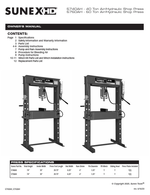
5740AH - 40 Ton Air/Hydraulic Shop Press 5750AH - 50 Ton Air/Hydraulic Shop PressCONTENTS:Page 1Specifications2Safety Information and Warranty Information 3Parts List4-6Assembly Instructions789Pump and Ram Assembly Instructions Procedure for Bleeding Air Pump Instructions10-11Winch Kit Parts List and Winch Installation Instructions 12Replacement Parts List© Copyright 2020, Sunex Tools ®SAFETY INFORMATIONThis symbol alerts you to the possibility of serious injury or death if instructions are not followed.This symbol alerts you to the possibility of damage to or destruction of equipment if instructions are not followed.Failure to heed these warnings may result in lossof load, damage to the press and/or failure resulting in property damage, personal or fatal injury. Thisoperating manual contains important details concern-ing the safe operation of this tool. The user must read and understand these details before any use of the tool. This manual must be retained for future reference.• Read, study, understand and follow all instructions before operating this press.• Always wear safety goggles, (users and bystanders).•Parts being pressed may splinter, shatter, or be ejected from the press at a dangerous rate of speed. Because there are a variety of press applications, it is the responsibility of the press owner to provide adequate guards, eye protection and protective clothing to the press operator.• Visual inspection of the press should be made before use, checking for signs of cracked welds, bent bed pins, loose or missing bolts, leaks, or any other structural damage. Corrections must be made before using the press.•Do not go near leaks. High pressure hydraulic uid can puncture skin and cause serious injury,gangrene, or death. If injured, seek emergency medical help as immediate surgery is required to remove the uid.• Prior to use make sure the press is securely anchored to a concrete oor.•Keep hands, arms, feet, and legs out of work area. Accidental slippage can result in personal injury.• Always use an accurate force gauge to measure pressing force.• Do not exceed the rated capacity or tamper with the pressure/force settings. When attachments and adapters are used the rated capacity of the system shall be no greater than the rated capacity of the lowest rated component or combination of components that make up the system. • Avoid off-center loads. Offset loads can damage ram and may cause load to eject at a dangerous rate of speed. Do not use any spacer or extender between the press ram plunger and the item being pressed. If there is not enough ram stroke, adjust the height of the movable bolster.•Remove all loads from movable bolster before attempting to adjust bolster height. Beware of possible falling bolster.•Press only on loads supported by movable bolster and press plates included. Do not support loads on oor or press frame legs.• When using any accessories such as press plates or arbor plates, be certain they are centered on the movable bolster and in full contact with both sides of the bolster.• Before applying load, be certain all movable bolster supporting pins are fully engaged. Verify lift cables (if equipped) are slack before pressing on the bolster.• Always use a bearing shield when pressing bearings.•Use caution when positioning work to be pressed to ensure the item to be pressed cannot be ejected at a dangerous rate of speed.• Release hydraulic pressure before loosening any ttings.• Maintain proper hydraulic uid levels.• Do not make any alterations or modi cations to the press.•This product may contain one or more chemicals known to the State of California to cause cancer and birth defects or other reproductive harm. Wash hands thoroughly after handling.•Failure to heed and understand these markings may result in serious or fatal personal injury and/or property damage.OWNER/USER RESPONSIBILITYThe owner and/or user must have an understanding of the manufacturer'soperating instructions and warnings before using this press. Personnel involvedin the use and operation of equipment shall be careful, competent, trained,and quali ed in the safe operation of the equipment and its proper use whenservicing motor vehicles and their components. Warning information shouldbe emphasized and understood.If the operator is not uent in English, the manufacturer's instructions andwarnings shall be read to and discussed with the operator in the operator'snative language by the purchaser/owner, making sure that the operatorcomprehends its contents.Owner and/or user must study and maintain for future reference the manufactur-er’s instructions. Owner and/or user is responsible for keeping all warning labels and instruction manuals legible and intact. Replacement labels and literature are available from the manufacturers.INSPECTIONVisual inspection of the shop press should be made before each use of the press, checking for damaged, loose or missing parts. Each press must be inspected by a manufacturer’s repair facility immediately, if subjected to an abnormal load or shock. Any press which appears to be damaged in any way, is found to be badly worn, or operates abnormally must be removed fromservice until necessary repairs are made by a manufacturers's authorized repair facility. It is recommended that an annual inspection of the press be made by a manufacturer’s authorized repair facility and that any defective parts, decals or warning labels be replaced with manufacturer’s speci ed parts. A list of authorized repair facilities is available from the manufacturer.SAFETY INSTRUCTIONS•CHECK YOUR LOCAL, STATE AND FEDERAL REGULATIONSREGARDING THE SAFE USE OF THIS EQUIPMENT.•Your safety is top priority. Please handle equipment with care.•Fully retract unit and remove all items from the press bed frame.•Support the press bed, and remove the pins.•Raise or lower bed to desired height and reinstall press pins. Be certainpins are fully engaged in the parallel anges of the upright columns.•Position press on a at, level, hard surface, preferably concrete.Make sure all nuts and bolts are tight.•Clear the area of bystanders, especially small children, before using.•Set the press bed to the required height. The press is most effectivewhen the work piece is located 1 inch below the ram’s retracted position.The compression stroke can include the entire 5 inch working range.•The press is designed to exert a force on anything which is positionedbeneath its ram. The work piece can pop out from under the ram at a high rate of speed and injure someone.•Pressing Bearings: It is essential that you use the bearing shield whenpressing bearings on or off.LIMITED WARRANTY:SUNEX INTERNATIONAL, INC. WARRANTS TO ITS CUSTOMERS THAT THE COMPANY’S SUNEX TOOLS ® BRANDED PRODUCTS ARE FREE FROM DEFECTS IN WORKMANSHIP AND MATERIALS.Sunex International, Inc. will repair or replace its Sunex T ools ® branded products which fail to give satisfactory service due to defective workmanship or materials, based upon the terms and conditions of the following described warranty plans attributed to that speci c product. This product carries a ONE-YEAR warranty. During this warranty period, Sunex T ools ® will repair or replace at our option any part or unit which proves to be defective in material or workmanship. Other important warranty information....This warranty does not cover damage to equipment or tools arising fromalteration, abuse, misuse, damage and does not cover any repairs or replace-ment made by anyone other than Sunex Tools ® or its authorized warranty service centers. The foregoing obligation is Sunex Tools ®’ sole liability under this or any implied warranty and under no circumstances shall we be liable for any incidental or consequential damages. Note: Some states do not allow the exclusion or limitation of incidental or consequential damages, so the abovelimitation or exclusion may not apply to you. Return equipment or parts to Sunex Tools ®, transportation prepaid. Be certain to include your name and address, evidence of the purchase date, and description of the suspected defect.If you have any questions about warranty service, please write to Sunex Tools ®.This warranty gives you speci c legal rights and you may also have other rightswhich vary from state to state. Repair kits and replacement parts are available for many of Sunex Tools ® products regardless of whether or not the product is still covered by a warranty plan.SHIPPING ADDRESS: MAILING ADDRESS:Sunex Tools Sunex Tools 315 Hawkins Rd. P .O. Box 4215Travelers Rest, South Carolina 29690 Greenville, South Carolina 29608THIS OPERATING MANUAL CONTAINS IMPORTANT SAFETY INFORMATION. READ CAREFULLY AND UNDERSTAND ALL INFORMATION BEFORE OPERATING THIS TOOL. SAVE THIS MANUAL FOR FUTURE USE.WARNING: This product can expose you to chemicals including nickel, which is known to the State of California to cause cancer and birth defects or other reproductive harm.For more information go to .Press Frame - 1Press Bed - 1Press Feet - 2Z Bar - 11/2"-13 x 1-1/2" Hex Head Bolts - 101/2" Nuts - 10Air MotorPump and Ram - 1Pump Extension Handle - 11" x 3" x 14"Press Plates - 2Accessory only -Not needed for assemblyPushing Adapter - 1Accessory only -Not needed for assemblyBearing Shield - 1Accessory only -Not needed for assemblyESTIMATED ASSEMBLY TIME: 30 MINUTESACCESSORIESASSEMBL CONTINUEDPUMP AND RAM ASSEMBL Y INSTRUCTIONSPROCEDURE FOR BLEEDING AIRPUMP INSTRUCTIONSWINCH INSTALLATION INSTRUCTIONS CONTINUED。
2023 Integra模型系列新版本车身修理信息说明书

Body Repair NewsJune 2022 Version 12023 Integra Model Series: New Body Repair InformationAPPLIES TO2023 Integra Model SeriesNOTE: This publication contains a summary of new body and vehicle technologies that may affect collision and other body repairs. Always refer to the service information and body repair manual (BRM) for complete repair information. A subscription may be purchased at . OVERVIEW OF BODY FEATURES• Next-Generation Advanced Compatibility Engineering™ (ACE™) body structure. • Body construction using high-strength steel (HSS) and advanced high-strength steel.• Aluminum hood panel, and front and rear bumper beams for weight reduction and improved fuel economy. • 1500 MPa inner and outer door stiffener rings.BODY CONSTRUCTION AND HIGH STRENGTH STEEL CONTENT•Steel parts are color coded based on their tensile strength in megapascals (MPa).•High-strength steel (HSS) is defined as any steel with a tensile strength of 340 MPa or higher.•Ultra-high-strength steel (UHSS) is defined as any steel with a tensile strength of 980 MPa or higher.•Steel repair and welding procedures vary depending on the tensile strength of the parts involved.NOTE: The illustrations below are for general reference only. Some body parts are constructed from multiple layers of different tensile strength steels. Always refer to the body construction section of the BRM for specific steel tensile strength information.ALUMINUM PARTS & REPAIRABILITYThe hood of the 2023 Integra model series uses aluminum alloy construction. Minor damage to the aluminum hood may be repaired by body shops that have dedicated aluminum repair facilities and tools.RESIN COMPOSITE FRONT BULKHEADThis vehicle has a front bulkhead assembly constructed of resin composite material.•The bulkhead design improves engine compartment access during factory assembly and service.•The cooling fans, radiator, A/C condenser, hood lock, outside air temperature sensor, and related piping/components are attached to the front bulkhead.• A damaged bulkhead must be replaced.•For more details, refer to front bulkhead replacement in the body repair manual.LASER BRAZED ROOF PANELLaser brazed roof panels require a combination of welding, and the use of adhesives and mechanical fasteners for replacement. Refer to the roof panel replacement procedure for more details.REAR WHEEL ARCH HEM JOINTDuring the replacement of the rear side outer panel, it will be necessary to hem the entire wheel arch using Acura special tools or modified commercially available tools. Refer to the outer panel side area replacement procedure for additional details including information on how to modify existing hemming pliers.If needed, the Acura Special Service Tool set below is available for purchase from your local Acura dealer.Tool Number Description Note07AAC-TY2A100 PLIER SET, HEMMING 3-Piece setNEW DRIVING SUPPORT SYSTEMMultipurpose Camera AimingThe 2023 Integra model series is equipped with a new driving support system that uses only the multipurpose camera and no millimeter radar unit. The multipurpose camera allows both dynamic and static aiming. Technicians now have the option to do either type of aiming depending on what their repair facility allows, or weather and traffic conditions.Refer to the following procedures for more details:•Multipurpose Camera Aiming [Static Aiming]•Multipurpose Camera Aiming [Dynamic Camera Aiming]Blind Spot Information (BSI) AimingThe 2023 Integra model series is also equipped with a new style BSI radar unit. Unlike other models, the Integra does not require the conventional BSI Radar Unit Aiming Inspection procedure. The system is now capable of self-learning while the vehicle is driven more than 20 mph (32 km/h). However, it is important that the BSI learning status is reset using the i-HDS whenever the following is done:•After removing and reinstalling one or both of the BSI radar units.•After repairing the rear panel where the BSI radar unit mounts.•When any of the following DTCs are stored:- B18B8 Left Side BSI Radar Unit Azimuth Off Alignment- B1E68 Right Side BSI Radar Unit Azimuth Off Alignment- B18BF Left Side BSI Radar Unit Temporary Azimuth Off Alignment- B1E6F Right Side BSI Radar Unit Temporary Azimuth Off AlignmentRefer to the following for more information:•BSI System Learning Value Reset•BSI System DescriptionNOTE: When the status is reset, the system is limited to 9.8 ft (3 m) of detection until the self-learning is complete.Blind spot Information (BSI) Rear Bumper Repair TemplatesThe 2023 Integra model series BSI radar units behind the rear bumper extend the detection range of previous systems but require extra consideration when repairing the rear bumper.The radar waves passing through the rear bumper are more affected by the type and location of the repair. Cracks or dents within the radar wave emission range cannot be repaired and will require bumper replacement. Scratches inside or extending into the radar wave emission range will require the whole area to be painted and polished.To assist technicians in determining where the radar wave emission area is, a printable template is provided in the body repair manual. This template can be taped onto the bumper and will help determine if the bumper can be repaired or will require replacement.Refer to the following for a printable template and more details:•Template Printed on Paper for Radar Wave Emission Range [Blind Spot Information System]•Precautions for Handling Bumpers [Blind Spot Information System]SUSPENSION BUSHING TIGHTENING PROCEDUREIn order to improve the ride, comfort, and avoid excessive twisting of the suspension bushings, the tightening of some specified suspension components must be done at the vehicle ride height with the driver seated. Depending on the bushing being tightened, the ride height can be simulated on the ground with weight in the vehicle, or the suspension component can be adjusted to ride height position.Refer to the Tightening Procedure of Suspension Bushing for more detail.ECU KEY WRITEA security key code protocol is being introduced for certain electronic control units (ECUs). This protocol provides secured communication between control units, helping to prevent cyberattacks from outside sources.When replacing control units like the VSA modulator control unit, you will need to access the ECU Key Write application in the i-HDS. For more information, refer to the job aid, Using the ECU Key Write Application in the i-HDS.END。
莱驰研磨仪维修手册_rm200_英文版

Repair Manual for Mortar GrinderType RM 2001 Notes on the Repair Manual1.1 General PointsThis repair manual for the type RM 200 mortargrinder contains all the information necessary forthe areas named in the table of contents.For your own safety, we recommend that you havethe necessary repairs done only by Retsch GmbH oran authorised agency (service technicians).If repairs that are not described in this manual arenecessary, please consult your supplier or contactRetsch GmbH directly.Retsch GmbHRheinischestr.3642781 Haan / RheinlandGermany1.2 Necessary Documents• Repair Manual• Operating Instructions• Inspection Instructions Doc. No. 98.001.01931.3 Necessary General Inspections• Insulation test as in EN 60204-1 (VDE 0113)• Protective conductor test EN 60204-1 (VDE 0113)• Voltage testing as in EN 60204-1 (VDE 0113)Please refer to Inspection Instruction Doc. No.98.001.0193 for the permissible measurements.1.4 ToolsThe following tools should be ready to hand:Phillips screwdriver 2x100Screwdriver 5x1002A/FHexkey3A/FHexkeyOpen-jaw wrench A/F 5.5Open-jaw wrench A/F 7Open-jaw wrench A/F 81Notes on the Repair Manual (2)1.1General Points (2)1.2Necessary Documents (2)1.3Necessary General Inspections (2)1.4Tools (2)1.5Description of the Device (4)1.6View of the Milling Chamber (6)2Instructions for Repairs and Dismantling (7)2.1Taking off the Hood (7)2.2Setting the Lock Pretensioning (8)2.3Dismantling the Housing (8)2.4Dismantling the Housing Flange (9)2.5Dismantling the Bearing Sleeve (10)2.6Dismantling the Bearing Flange (11)2.7Replacing the Needle Bearing in the Bearing Flange(Pestle Bearing) (11)2.8Replacing the Motor Flange (12)2.9Replacing the Motor (12)2.10Replacing the Motor Pin (14)2.11Setting the Magnetic Switch on the Lid (15)2.12Replacing the Control (16)2.13Replacing and Setting the Scraper (19)2.14Adjusting the Scraper to the Mortar (20)2.15Checking the Scraper Setting (21)2.16Trial Milling Operation (21)2.17Replacing the Rubber Buffer on the Scraper (22)2.18Mounting and Setting the Rotary Knobs (23)2.19Replacing the Window Panes (23)2.20Replacing the Bearing Plate for the Pestle (24)2.21Replacing the Motor Flange Bearing (25)2.22Replacing the Scraper Bearing (26)2.23Replacing the ON/OFF Switch (26)2.24Replacing the Device Fuse (27)3Technical Data (28)3.1Analyses of the Materials (29)4Parts Lists (30)4.1Part 1 Individual Components (30)4.2Part 3 Variant Assignment (32)4.3Spare Parts List for 2-Year Operation (33)4.4Part 5 Recommended Spare Parts (33)5Part 4 Drawings (34)5.1RM200 Views and Sections (34)5.2Dimensional Data Sheet (41)5.3Circuit Diagram (43)1.5 Description of the DeviceDiagram of the Parts of the Device:Front ViewRear ViewGKLMFIJ EHElement Description FunctionA Device socket Connection for the device’s power cableB Fuse tray Holds two glass fusesC Type plate Information on the device and connectedloadsD ON / OFF switch For turning the RM200 on and offE Display and operating unit:see below for explanations Setting the time and starting / stopping the machineF Lock handle For opening and locking the milling chamberG Rotary grip - pestle pressureadjustmentTurning alters the pestle contact pressureH Scale Guide for setting the pestle pressureI Filling aperture Sample material is filled in here.J Viewing window Allows the milling process to be monitored,especially for adjusting the scraperK Setting knob for scraper Sets the contact pressure or gap for thescraperL Pestle setting knob For adjusting the pestle in relation to themortar wallM Hood Closes the milling chamber1.6 View of the Milling ChamberElement DescriptionFunctionV Pestle Crushes and mills the material W Mortar Holds the material to be milledX ScraperMixes the milled material thoroughly and scrapes off any material adhering to the mortar Y Fixing screw for scraper Holds the scraper in place with the screwed-on fixing clamp ZFixing clamp for scraperClamps the scraperYXZ2 Instructions for Repairs and Dismantling2.1 Taking off the HoodTools requiredTorx 25; Hex key 2mm; Open-end wrench 8mmSpare Parts RequiredFig. 2.1-1 1. Disconnect the C mains plug. 2. Remove pestle V and mortar W 3. Unscrew (2x Fs screws) and remove the F lock handle.4. Unscrew the G rotary grip that is on the pestle pressureadjustment mechanism5. Unscrew the threaded pins at both rotary knobs K /L6. Unscrew both rotary knobs K /L.7. Take the adjusting washers and Belleville washers off theaxles.8. Screw in the left axle for the scraper setting mechanism K byturning it in a clockwise direction as far downwards as possible 9. Screw in the right axle for the pestle adjustment L byturning it in an anticlockwise direction as far downwards aspossible10. Unscrew and take out the 4 housing screws (Torx).11. Align the Lf bearing flange pestle until the axle falls down inthe lid of the housing12. Pull the hood upwards and offFig. 2.1-2Fs FK L LfGs2.2 Setting the Lock PretensioningTools requiredHex key 2mmSpare parts requiredDescription of the procedure Fig. 2.2-1 The lock pretensioning on the lock handle F can be influenced by the adjustment of the rubber buffer Gp .1. Open the hood H and unscrew the threaded pin Gw .2. Increase the lock tension: (unscrew)Turn the Gp rubber buffer in an anticlockwise direction.3. Reduce lock tension: (tighten)Turn the Gp rubber buffer in a clockwise direction.4. Check the lock pretensioning by closing the hood H andby tightening the lock handle F2.3 Dismantling the HousingTools requiredPhillips screwdriver size 2Spare parts requiredDescription of the procedure Fig. 2.3-1 1. Remove the 5 Gs housing screws Fig. 2.3-12. Tilt the RM200 on its side and twist off the 4 feet Sf . Fig.2.3-23. Once the RM200 has been set up on the bottom part ofthe housing, you can carefully take off the top part of the housing. Pay attention to the cabling in the housing. Fig. 2.3-3 Fig. 2.3-4Fig. 2.3-4GsGsGsSfGwHGpF2.4 Dismantling the Housing Flange Tools requiredHex key 5mmScrewdriver 5x100Spare parts requiredDescription of the procedureFig. 2.4-1 1. See Chapter 2.1 Taking off the Hood and 2.8 Replacingthe Motor Flange2. Loosen the three Sg screws.3. Tilt the housing flange on its side carefully withoutdamaging the cables.Note: the K1 cable runs from the Hall sensor to thecontrol and the K2 cable runs from the hood switch to the control also.4. There are two ways of loosening the K1 cable ordismantling the Hall sensor:a. Loosen the counternut at the Hall sensor andthen unscrew and remove the Hall sensor.b. If the housing has been dismantled already, theK1 cable can be taken off the control.5. There are also two ways of loosening the K2 cable orremoving the Hs hood switch:a. Loosen the four Sa screws on the rear coverplate Al. Now loosen the counter nut at the hoodswitch and twist it out.b. If the housing has been dismantled already, theK2 cable can also be disconnected from thecontrol and taken out of the housing.K2Al HsSg2.5 Dismantling the Bearing Sleeve Tools requiredScrewdriver 5 mm x 100Water pump pliersSpare parts requiredDescription of the procedureFig. 2.5-1Fig. 2.5-2 Fig. 2.5-3Fig. 2.5-4GKl2.6 Dismantling the Bearing Flange Tools requiredHex key 4mmSpare parts requiredDescription of the procedure1. For the preliminary work, see Chapter2.1Taking off theHood2. For further preliminary work, see Chapter 2.5Dismantling the Bearing Sleeve3. Remove the rubber ring covering the three screws, S1,S2 and S3.4. Fold down the head plate.5. Loosen and remove the S1, S2 and S3 screws. Fig. 2.6-16. When inserting the S1, S2 and S3 screws, secure themwith Loctite.2.7 Replacing the Needle Bearing in the Bearing Flange(Pestle Bearing)Tools requiredDrift punchSpare parts required1 x sealing ring 05.111.00792 x needle bearings 05.484.0009Description of the procedure1. For the preliminary work, see Chapter2.6 Dismantlingthe Bearing Flange2. Remove the Sm sealing ring Fig. 2.7-13. The two bearings are then tapped out from both sideswith a drift punch.4. Now, use a pressing implement to press the new needlebearings and the spacer into the bearing flange.5. Insert the new Sm sealing ring.6. The new needle bearings are secured with Loctite 241and then greased on the inside.S1S32.8 Replacing the Motor FlangeTools required2 screws M5x50 Rubber hammer 2x hex key 4 mmSpare parts requiredDescription of the procedure 1. Openthe M hood. 2. Then, remove the pestle.3. Place two metal sheets underneath as protection forthe motor flange. Insert two screws with M5 threading and a minimum depth of 50 mm into the two Ab forcing bores. Fig. 2.8-1 4. Tighten the screws at the same time in order topress the Mf motor flange off the motor axle in parallel alignment. 5. Insert the motor flange in such a way that the sloton the underside engages with the pin.6. Use a rubber hammer to tap in the new motorflange and in doing so take care that it enters the bearing in a straight line.2.9 Replacing the MotorTools requiredOpen-jaw wrench 8/8 Rapidly acting adhesiveSpare parts requiredThe 03.713.0065 divider RM200 Foam Cellofoam 460UL might be needed. Motor to suit the voltage variantDescription of the procedure 1. For the preliminary work, see 2.3 Dismantling the Housing / 2.12 Replacing the Control2. Remove the K1 K2 K3 K4 cables as stated in Chapter2.12 Replacing the Control3. Loosen the cables at the six-fold distribution in the Evearthing terminal block Fig. 2.9-24. Remove the connection cable to the operating capacitorBk Fig. 2.9-15. Now carefully take the Sc foam divider out of the greyCellofoam. The foam divider is fixed in position with a few small adhesive dots. Fig. 2.9-4When assembling, take care that the foam divider is in the correct position so that the air can circulate appropriately! Fig. 2.9-3 Use rapidly acting adhesive on 4 different adhesive dots to fix the foam divider in position on the motor ventilator hood6. Remove the four motor mounting screwsFig. 2.9-5 Fig. 2.9-6AbFig. 2.9-3Fig. 2.9-4Fig. 2.9-5Fig. 2.9-62.10 Replacing the Motor PinTools requiredDrift punch AdhesiveSpare parts requiredDescription of the procedureFig. 2.10-11. To remove the motor pin, first clamp the motor axle in avice.The motor axle will otherwise be damaged when it is being tapped out! Fig. 2.10-1 / Fig. 2.10-22. Use soft jaws made of aluminium or copper in order notto damage the shaft. The motor shaft must be clamped so that the motor pin points upwards and can be tapped out with a drift punch. Fig. 2.10-2 3. Using the hammer and drift, tap the pin out carefully. 4. Then, apply Loctite 270 adhesive to the new pin and tapit in carefully and centre it precisely.5. The pin may not jut out on either side more than 8.7mm from the axle.Fig. 2.10-22.11 Setting the Magnetic Switch on the LidTools requiredOpen-jaw wrench 13 mmPhillips screwdriver 2 mmSpare parts requiredDescription of the procedure1. Loosen the four screws Rs.2. Remove the rear panel Rb.Rs3. Loosen the counter nut at the magnetic switchon the lid Md.4. While the machine is running, adjust theswitching point on the Md magnetic switch onthe lid by tightening or loosening the screws.5. The switch must trip before the hand can reachinto the milling chamber. The opening width ofthe hood may not exceed a maximum 80 mm.6. The magnetic switch on the lid may not comein contact with the opened lid!7. Then, carefully tighten the counter nut again.Plastic!Check for correct functioning1. Open the lid, the magnet must switch off the RM200 at a gap width not exceeding 80mm. The F4 fault alarm appears.2. Take out the pestle.3. Close the cover.4. Press STOP to cancel the F4 fault alarm.5. If necessary, turn the Md magnetic switch upwards and check it again. (Steps 1-4)6. Tighten the Rb cover again7. Insert the pestle again8. The RM 200 is now ready for operation again.Inspections: general inspection in accordance with 1.3 Necessary General Inspections2.12 Replacing the ControlTools required7- mm keyPhillips screwdriver Size 1Spare parts required03.748.0116Description of the procedure1. Disconnect the mains plug.2. For the preliminary work, see Chapter 2.3Dismantling theHousing3. Loosen the four Sb screws in the bottom panel Fig. 2.12-14. Remove the three cables: K1 cable to the Hall sensor, K2cable to the hood switch, K3 current supply to the motorSee also Diagram Fig. 2.12-8/ Fig. 2.12-85. Remove the D power switch and remove the cables to theK4 mains input.6. Disconnect the plug to the St keypad membraneSbFig. 2.12-6Loosen the three screws on the Ss control board7. Fig. 2.12-78. Then, set the control to the correct mains voltage.9. Press the – + START buttons at the same time and turnon the machine at the D power switch.10. Press the START button again.11. Press the – or + buttons to choose the right program forthe voltage or frequency.See Fig. 2.12-2 and Table12. Then save the setting by pressing the Stop buttonFig. 2.12-2Fig. 2.12-7SsSs DSt K2SsFig. 2.12-8Item Designation Article numberA1 Device plug 05.230.0008 A2 ON/OFF switch 05.703.0168A3 Operating capacitor 05.379.001 /..04/..05 A4 Hall sensor 05.569.0020A5 Motor 05.441.0283/..284/..286/..287/..288/..374/..387 A6 Control board 03.748.0116 A7 Switch on lid 05.703.0249A8 Keyboard membrane03.799.0039Gehäuseunterteil = lower section of the housingK1K2K3K4DSt2.13 Replacing and Setting the ScraperTools requiredSupplied Torx screwdriver T20Spare parts requiredDescription of the procedureFig. 2.13-11. Open the hood and fold it backwards and down.2. Use the enclosed screwdriver to loosen and take outmounting screw Y.3. Swing out the fastening clip4. Remove and replace the scraper.5. Hook in the fastening clip Z again and insert screw Yloosely. The scraper can be moved forwards or backwards in its slot. Before tightening the screw, push the scraper backwards. 6. Close the hood and check visually or with the material tobe milled if the scraper is in proper contact with the mortar. See also: “Checking the Scraper Setting ”.7. If the scraper doesn’t completely touch the bottom of themortar and the inside wall of the mortar (dotted line inFig. 2.13-2), reset it.8. To do this, loosen mounting screw Y again and move thescraper. Tighten the screw again and check if the scraper is now in contact.Fig. 2.13-2YZX2.14 Adjusting the Scraper to the MortarTools requiredSupplied Torx screwdriver T20Spare parts requiredDescription of the procedure When the machine is delivered or when a scraper is re-ordered, it may be necessary to regrind the scraper X . ThisFig. 2.14-1Condition on Delivery groundX2.15 Checking the Scraper SettingDescription of the procedure Fig. 2.15-1 Optimum settings in contact pressure and contact with the bottom of the mortar are necessary for the scraper to work properly.The best way to assess this is to carry out a neutral milling operation.2.16 Trial Milling OperationFig. 2.16-1We recommend the following mixture as neutral millingmaterial for this trial :e.g. 4 – 5 teaspoons of powder sugar5 – 10 ml water1. With the mortar empty, close the lid and press thelock handle until it shuts.2. Turn the G rotary grip to the “0” setting on the Hscale.3. Switch on the device and start operation by pressingthe Q start button.4. Add the powder sugar through the I window openingon the right and then pour the water in.If the scraper has been adjusted correctly, a pasty mixturewill form that does not stick to the inside wall or to thebottom of the mortar behind the scraper.See Fig. 2.15-1 / Fig. 2.16-1To check the milling visually, look through the J window onthe left.wrongcorrect2.17 Replacing the Rubber Buffer on the Scraper Tools requiredHex key 3 mmHex key 4 mmSpare parts requiredDescription of the procedureFig. 2.17-1 1. For the preliminary work, see Chapter 2.1 Taking off2. Remove the Gb screw that keeps the Ga scraper’srubber buffer in place on the spindle axle of the scraper adjustment mechanism.Fig. 2.17-23. Remove the Gc screw on the scraper linking bar(hexagonal recess) Fig. 2.17-24. The Ga rubber buffer can be replaced now.5. The Gb screw must be secured with Loctite 241.Fig. 2.17-3Ga GaGbGc2.18 Mounting and Setting the Rotary Knobs Tools requiredHex key 1.5 mmSpare parts requiredDescription of the procedureFig. 2.18-1 1. Put the adjusting washer on the spindle and push theBelleville washer with the smaller diameter against the adjusting washer.2. Screw the rotary knob onto the spindle until it is firmlypositioned without play.3. Secure the rotary knob with the threaded pin. See alsoFig. 5.1-92.19 Replacing the Window Panes Tools requiredSpare parts requiredDescription of the procedureFig. 2.19-1 The hinge axles for the Fs window panes are offset and for that reason it is important not to mix up the window panes when changing them. The axle is offset upwards and must be on top when installed. If in doubt, refer to Fig. 2.19-2 to see which pane fits into which side.1. Open the pane as far as it can go and press further untilthe hinges disengage.2. Install by pressing the hinge axle into the hinges.3. Test: if installed correctly, the panes can be opened a lotwider than 90°, as shown in Fig. 2.19-1. If not, switchthe two window panes.FsFig. 2.19-22.20 Replacing the Bearing Plate for the Pestle Tools requiredMS13 / MS 10Screwdriver 10 mmSpare parts requiredDescription of the procedureFig. 2.20-1 Fig. 2.20-2 Flat head screw NoteLEFT-HAND THREAD!2.21 Replacing the Motor Flange Bearing Tools requiredSpare parts requiredDescription of the procedureFig. 2.21-1 1. For the preliminary work, see 2.4 Dismantling theHousing Flange2. After the preliminary work the Mfl motor flange bearingcan be pressed out, as shown in Fig. 2.21-2 .Fig. 2.21-2Mfl2.22 Replacing the Scraper Bearing Tools requiredHex key 4 mmHex key 3 mmSpare parts requiredDescription of the procedureFig. 2.22-1 1. Twist out the Gb screw.2. Twist the Sa screw out of the scraper bearing.3. Take off the Sch disc.4. Pull off the Al scraper linking bar.5. Take off the Bb bronze bushing.6. When it is being fitted, the collar of the bushing pointsdownwards!7. If the scraper linking bar can only be turned withdifficulty, insert an adjusting washer 0.5 mm under the bronze bushing Bb.8. Secure the Sa screw with Loctite.2.23 Replacing the ON/OFF Switch Tools requiredSpare parts requiredDescription of the procedureFig. 2.23-1 1. For the preliminary work, see 2.12 Replacing the Control2. Make sure when inserting the new power switch that theOn/Off position is correct in relation to the housingcover.3. Reconnect the cables in conformance to the circuitdiagram.4. Assemble in reverse order.5. Inspections : general inspections as specified on Page 2SaSchAlBp2.24 Replacing the Device FuseTools requirednot applicableSpare parts requiredfor 230-240V 2 fuses MT3,15A Order No. 05.699.0016for 100-110V 2 fuses MT6, 30A Order No. 05.699.0053Description of the procedure1. Disconnect the mains plug C2. Press in the hook on the B fuse holder3. Take out the B fuse holder4. Replace the fuses5. insert the B fuse holder3 Technical DataDriveSingle-phase worm gear motorSee type plateRated power130 wattsIP53Noise characteristic values Noise measurement according to DIN 45635-031-01-KL3Intensity of sound l WA = 85 dB(A)Workplace-related emission level L pAeq = 72 dB(A)Operating conditions:Material to be milled = quartz sand, grain size < 1 mm100 rpm at rated loadOverload protectionElectronic protection by means of the control:The power is monitored and switched off in cases ofcontinuous overloadingDevice fuses2x glass fuses at the rearMT 3.15A at 230-240VMT 6.00A at 100-110VHeight 585 mm when the lid is openWidth 400mmDepth 510 mm when the lid is openApprox. 24 kg without mortar and pestleWidth 400 mm x depth 500 mmIt is not necessary to observe any safety distancemortar * Tungsten carbide* Special steel 2* Stainless steel* Agate* Sintered corundum* Zirconium oxide* Hard porcelain3.1 Analyses of the MaterialsTungsten carbide Hardness approx. 73 HRC94.000%Analysis: WC06.000%CoSpecial steel 2 / 1.2080 H ardness approx. 60 HRC00.400%Si00.450%Mn00.030%P00.030%S12.000%Cr85.340%FeStainless steel 1.4034 Hardness approx. 53 HRC13.000%Analysis: Cr00.030%SP00.050%01.000%Mn01.000%Si00.420%C84.500%FeAgate Hardness approx. 7.0 n. MohsAnalysis: SiO2 99.910%Al2O3 00.020%Na2O 00.020%Fe2O3 00.010%K2O 00.010%00.010%MnOMgO00.010%00.010%CaOSintered corundum 1 Hardness approx. 9.0 n. Mohs2 3SiO2 00.075%00.075%MgO00.070%CaONa2O 0.0100%Fe2O3 00.010%Zirconium oxide Hardness approx. 8.5 n. Mohs2SiO2 00.170%MgO01.400%01.400%CaOFe2O3 00.030%Hard porcelain Hardness approx. 8.0 n. MohsAl2O3 34.000%K2O 03.000%01.000%MgOCaO01.000%The above percentages for the analysed parts are average values.4 Parts Lists4.1 Part 1 Individual ComponentsItem Qty. Article no. Designation02.222.03771 1Lower housing section03.222.03952 1Upper housing section03.049.00033 1Panel bottom03.049.00014 1Panel top03.222.03835 1Hood03.222.03826 1Housing flange (cast aluminium, painted)03.398.00057 1Head plate (cast aluminium, painted)03.748.01168 1Control board03.799.00399 1Keypad membrane10 4 03.244.0016Rubber foot11 4 03.089.0002Spacer bolt (in the metal housing)12 1 03.399.0102Cable harness RM200 (incl. Hall sensor + magnetic switch on the lid) 13 2 03.706.0261Window14 4 03.709.0046Hinge for window15 4 03.709.0047Hinge axle for window16 1 03.183.0048Mortar plate (flange)17 1 03.241.0032Sealing foam rubber grey (mortar plate)18 1 03.007.0093Lid axle19 1 03.861.0022Sealing washer Ø172x140x4 (Sealing ring mortar lid )20 1 03.409.0176Scraper linking bar RM200 complete (welded, incl. bushing)21 1 03.409.0177Scraper clamp22 1 03.403.0052Bearing bushing scraper (bronze)24 1 03.862.0011Scraper Vulkollan®25 1 03.642.0015Spindle scraper adjustment26 2 03.070.0057Setting knob (scraper + pestle )27 1 03.406.0010Bearing plate pestle28 1 03.403.0049Bearing flange pestle29 1 03.403.0055Bearing sleeve pestle30 1 03.261.0040Retainer pestle snapper (for O ring)31 1 03.658.0004Clamping sleeve pestle (handle)32 1 03.706.0254Support ring pestle bearing top33 1 03.112.0073Spacer sleeve spring pestle clamping device34 1 03.390.0004Clamping plate for pestle spring (VA spring steel)35 2 03.089.0020Spacer sleeve bearing plate P36 1 03.403.0054Bearing bushing bearing plate P (bronze)37 1 03.403.0053Bearing block pestle plate38 1 03.642.0014Spindle pestle adjustment39 1 03.243.0054Rubber bump stop (head plate + housing flange rear) dia. 12x340 1 03.009.0074Cover plate (rear)41 1 03.731.0479Sign Retsch Logo sticker42 1 03.243.0058Rubber sealing top hood - bearing flange P.43 1 03.731.0453Type plate44 1 03.731.0441Caution sign45 1 03.731.0495Plate with device name RM20046 1 03.731.0473Plate with Retsch Internet Logo47 2 03.243.0056Rubber bump stop for window RM20048 3 03.042.0319Bolt lock RM20049 1 03.867.0068Lock handle RM20050 1 03.867.0069Lock hook RM20051 1 03.867.0070Lock pusher RM20052 1 03.867.0071Lock holder RM20053 2 03.181.0102Leg spring lock RM20054 2 03.706.0268Washer retainer bottom 10.5x24x1 for pestle plate55 2 03.706.0267Washer retainer top 6.5 x 24 x 1.5 pestle plate56 1 03.706.0266Washer pivot bearing top 8.5 x 24 x 1.5 pestle plate57 1 03.706.0265Washer pivot bearing bottom 12.5 x 28 x 1 pestle plate58 1 03.243.0059Sealing washer bottom pestle head plate cellular polyurethane elastomer59 1 03.713.0065RM200 divider foam Cellofoam 460UL100 2 05.043.0164Collar bushing lid bearing GFM 12-14-15102 1 05.111.0019Sealing ring plate bearing Nilos 3206 av103 1 05.111.0186Sealing foam rubber bottom panel 0.6 m104 1 05.111.0079Sealing ring G 28-37-4105 1 05.114.0091O-Ring pestle arresting device dia. 24 x 4 FPM106 1 05.181.0070Pressure spring pestle clamping device107 1 05.230.0008Device plug (socket + fuse tray)108 4 05.231.0008Plain bearings bearing bushings IGUS GFM 081014-06109 4 05.727.0051Clamp to fix cables in place110 6 05.481.0008Blind rivet for cable clamp dia. 3111 2 05.484.0009Needle bearing pestle NK28-20112 1 05.617.0022Ball bearings 6201 2RS (pestle clamping device)113 1 05.641.0010Scale pestle114 1 08.647.0009Lock washer DIN 6799-10 mm for fixing the small ball bearings in place115 1 05.703.0168Switch (ON-OFF)116 0 05.703.0249Magnetic switch on the lid 29G2326117 3 05.368.0034Ball pestle arresting device (milling balls VA) dia. 5 mm118 1 05.737.0003Angular ball bearing plate119 8 05.710.0053Screw WN 1747 –K50 x 14 for panel top/bottom120 1 08.182.0026Flat head screw DIN 923 M6 x 8 for bearing block pestle pl.121 0 05.569.0020Hall sensor cykn8-02clo (contained in the cable harness)122 1 08.933.0190Cylinder head screw DIN 7984 M6x25 (for scraper) A2124 4 05.710.0072Screw Remform® 5x20for hood Torx Arnold forming technology WN156-3125 1 05.005.0020Rubber shock absorber scraper M5 dia.15 x 15 60° Shore A126 6 05.231.0021Sliding discs bearing plate P IGUS GTM 12-24-015127 1 08.221.0065Threaded pin M8x35 for pestle bearing plate128 2 08.221.0072Threaded pin M6x35 for pestle bearing plate129 3 08.933.0050Cylinder head screw M5x12 DIN 912 for pestle flange130 2 08.523.0021Adjusting washer 10x16x1 for pestle plate131 2 08.221.0071Set screw M4x4 45H DIN 916 with cup point for rotary knobs132 3 08.933.0068Cylinder head screw M6x35 DIN 933 for housing flange133 2 08.221.0060Set screw M5x5 A2 DIN 914 with cone point for lid axle and rubber buffer lock134 1 08.701.0018Washer A6.4 DIN 125 A2 for screw scraper bearing135 1 08.781.0008Belleville washer C25 A2 DIN 2093 (0.7 mm) for pestle plate pivot bearing136 2 08.781.0009Belleville washer C20 A2 DIN 2093 (0.5 mm) for pestle plate retainers on the right137 1 03.731.0451ISO 9001 sticker138 4 08.642.0006Hexagonal nut M5 A2K for fixing the motor in place139 4 08.701.0005Washer DIN 125 for fixing the motor in place A2K140 5 08.401.0006Pan head screw with cross recess M4x8 DIN 7985 for panel box rear and cover plate rear 141 13 05.453.0006 Round magnet for Hall sensor speed measuring and lid switch143 5 05.710.0052Ejot screw for control146 2 08.643.0020Countersunk head screw M5x16 A2 for lock hook150 2 05.710.0073Countersunk head screw 3x10 for hinge window on the right151 1 05.710.0074Countersunk head screw M4x10 Torx A2 for scraper152 1 08.643.0038Countersunk head screw M5x8 DIN 7991 A2 for rubber buffer scraper153 2 03.710.0075Countersunk head screw 3x15 for hinge window on the left。
航海英语一:船舶修理英语讲课讲稿

航海英语一:船舶修理英语航海英语一:船舶修理一、修理的种类Repair ListsKinds of Repair 修理的种类 Voyage Repair 航次修理Annual Repair 岁修修理 Guarantee Repair 保修修理Occasional Repair 临时修理 Additional Repair 补充修理、加帐修理三、有关船舶修理的句子Sentences Regarding Ship’s RepairRepair List and Expenses 修理单和费用I’ve come to check with you the items in your repair list.我是来和你核对修理单上的项目的。
We have some additional repair items. Here is the additional repair list.我们有些补充修理项目。
这是补充修理单。
Please make out the additional items within two days of the dry-docking of the ship. 请在船舶进坞后两天之内制出补充修理单。
Let’s discuss the items on the repair list one by one.让我们一项一项地讨论修理单上的项目。
If you have any questions about the repair list, you can talk to our chief officer/chief engineer/personnel on duty.如果对修理单你还有什么问题,可以和我们的大副/轮机长/值班室人员谈。
I think it’s better to make some alteration/modification to Item No. xx.我想最好对XX项修理内容做些更动/改变。
NRX系列电路保护器Ronis键锁套装安装与拆卸指南说明书
Series NRX circuit breaker Ronis key interlock kit installation and removal instructions• WARNING(1) ONLY QUALIFIED ELECTRICAL PERSONNEL SHOULD BE PERMITTED TO WORK ON THE EQUIPMENT.(2) ALWAYS DE-ENERGIZE PRIMARY AND SECONDARY CIRCUITS IF A CIRCUIT BREAKER CANNOT BE REMOVED TO A SAFE WORK LOCATION.(3) DRAWOUT CIRCUIT BREAKERS SHOULD BE LEVERED (RACKED) OUT TO THE DISCONNECT POSITION.(4) ALL CIRCUIT BREAKERS SHOULD BE SWITCHED TO THE OFF POSITION AND MECHANISM SPRINGS DISCHARGED.FAILURE TO FOLLOW THESE STEPS FOR ALL PROCEDURES DESCRIBED IN THIS INSTRUCTION LEAFLET COULD RESULT IN DEATH, BODILY INJURY, OR PROPERTY DAMAGE.• WARNINGTHE INSTRUCTIONS CONTAINED IN THIS IL AND ON PRODUCT LABELS HAVE TO BE FOLLOWED. OBSERVE THE FIVE SAFETY RULES: – DISCONNECTING– ENSURE THAT DEVICES CANNOT BE ACCIDENTALLY RESTARTED – VERIFY ISOLATION FROM THE SUPPLY – EARTHING AND SHORT-CIRCUITING – COVERING OR PROVIDING BARRIERS TO ADJACENT LIVE PARTSDISCONNECT THE EQUIPMENT FROM THE SUPPLY. USE ONLY AUTHORIZEDSPARE PARTS IN THE REPAIR OF THE EQUIPMENT. THE SPECIFIED MAINTENANCE INTERVALS AS WELL AS THE INSTRUCTIONS FOR REPAIR AND EXCHANGE MUST BE STRICTLY ADHERED TO PREVENT INJURY TO PERSONNEL AND DAMAGE TO THE SWITCHBOARD.Instructions apply to:UL489 Series NRF RF FrameIEC IZMX40UL1066/ANSI, UL489 Seris NRX NF FrameIEC IZMX162Series NRX circuit breaker Ronis key interlock kit installation and removalinstructionsEATON Instruction Leaflet IL01301040EEffective June 2016Noee:N The content of this IL applies to both PXR and Digitrip equipped breakers. Appearance of product may vary.Section 1: General informationThe key interlock secures the breaker in the “OFF” position. It is mounted in the upper portion of the breaker and can be viewed from the front cover. The customer supplies the keylock. The following safety features are provided.1. With NO key, the breaker is “OPEN” and cannot close.2. With the key ON (key in the cylinder) and rotated, the breaker is fully functional.3. The key cannot be removed when the breaker is ON (closed).Noee:N To remove the key, press the breaker “OFF” button, and rotate the key 90 degrees counterclockwise.Kio paros idenoificaoiNnRefer to (Figure 1) for visual identification of the parts listed below.(A) External protective ring (self-adhesive) (1)(B) Ronis lock 1351-10B (Dim A = 7 mm) with key (Ronis keylock notsupplied)(C) Metal mounting bracket (1)(D) M3 x 5 mm mounting screw (2)(E) Fiber retaining washer (2)(F) Large locking nut (1) (not part of kit, supplied with keylock)(G) Key lock lever (1)(H) Small locking nut (1) (not part of kit, supplied with keylock)(I) Spacer (1) for RF frame use only.1600 NRX SUB-TITLE IMAGE (12/15/2010)3Instruction Leaflet IL01301040EEffective June 2016Series NRX circuit breaker Ronis key interlock kit installation and removal instructionsEATON Section 2: Installation of key interlockProceed with the following 10 steps.Soep 1e: Remove the four screws (six for 4-pole breaker) holding the front cover in place, two on each side of the cover.Figure 2. Soep 1 – NF frame.Figure 3. Soep 1 – RF frame.Soep 2e: Remove the front cover. Pull down on the charging handle to simplify removal.Figure 4. Soep 2 – NF frame.Figure 5. Soep 2 – RF frame.Soep 3e: (NF frame Nnly) If this is a fixed circuit breaker, skip this step and proceed directly to Step 4. If this is a drawout circuit breaker, unscrew the three captive screws holding the secondary mounting bracket in place. This will permit the secondary mounting bracket to be moved down, providing access to the key interlock assembly’sthreaded mounting holes. No wires or connectors need to be removed or unplugged.4Series NRX circuit breaker Ronis key interlock kit installation and removalinstructionsEATON Instruction Leaflet IL01301040EEffective June 2016Figure 6.Soep 3 – NF frame.Soep 4.1e: (NF frame Nnly) Refer to (Figure 1) for assemblyorientation. Mount the lock (B) to the mounting bracket (C). Secure it in place with the large locking nut (F). Ensure that the large locking nut is firmly tightened.Soep 4.2e: (RF frame Nnly) Refer to (Figure 1) for assembly orientation. Install the spacer (I) onto the back of the lock (B) and then mount the mounting bracket (C). Be sure the spacer is trapped between the lock and the mounting bracket. Secure it in place with the large locking nut (F). Ensure that the large locking nut is firmly tightened.Noee:N Check for the proper key rotation direction. The key should be removable after rotating it all the way counterclockwiseSoep 5e: Install the key lock lever (G) onto the back of the lock and secure it in place with the small locking nut (H). Ensure that the small locking nut is firmly tightened. Three different assembled lock orientations are presented here for reference purposes.Figure 7. Soeps 4 and 5.Soep 6e: Identify the mounting location for the key lock assembly. Two threaded mounting holes are provided in the mounting tab to accommodate the two mounting screws (D) and two fiber retaining washers (E), which serve as spring washers when tightened. Position the key lock assembly and make sure the key lock lever (G) is trapped between the side plate and mounting bracket leg before tightening the two mounting screws. When properly positioned, secure it in place by tightening the mounting screws. Confirm the mounting bracket’s sheet metal tab is positioned under the plastic of the pushbutton plate.Use a small flat screwdriver to get the metal tab under the plastic.Figure 8. Soep 6 – NF frame.back and re-tighten the three captive secondary mounting bracket screws previously removed in Step 3 of this section starting with the center screw.Noee:N If any connectors were accidentally loosened, ensure they are pushed back into place.Soep 8e: With the key lock assembly now installed, place the front cover previously removed in Step 2 on an appropriate work surface back side up. Using a 26 mm unibit, preferably with a 26 mm upper size, carefully drill out a hole for the lock in the front cover. A drill point is provided in the back of the cover. Make certain that all particles are cleaned up.Soep 9e: Replace the front cover, and secure it in place with themounting screws previously removed in Step 1. Remove the adhesive backing from the external protective ring (A), and press it onto the front cover over the key lock.5Instruction Leaflet IL01301040EEffective June 2016Series NRX circuit breaker Ronis key interlock kit installation and removal instructionsEATON Figure 10. Soep 9.Soep 10e: Perform a functional test:1. With the key in the cylinder, press the red “Push To Open” button down and rotate the key counterclockwise. Remove the key. Charge the breaker.2. Push the green “Push To Close” button. The breaker should not close.3. Insert the key and rotate 90 degrees clockwise. Press the green button to close. The breaker should close.Noee:N A slight resistance might be felt and a click sound heard toward the end of the rotations clockwise or counterclockwise. This is perfectly normal.SecoiNn 3e: RemNval Nf key inoerlNckTo remove the key interlock, perform Steps 1 and 2 of Section 2. Complete the removal process by reversing the process as described in Steps 3 through 7 of Section 2. Replace the front cover.6Series NRX circuit breaker Ronis key interlock kit installation and removalinstructionsEATON Instruction Leaflet IL01301040EEffective June 2016Eaton is a registered trademark.All other trademarks are property of their respective owners.EatonElectrical Sector1000 Eaton Boulevard Cleveland, OH 44122United States877-ETN-CARE (877-386-2273)© 2016 EatonAll Rights Reserved Printed in USAPublication No. IL01301040E/TBG001305Part No. IL01301040EH07June 2016Disclaimer of warranties and limitation of liabilityThe information, recommendations, descriptions, and safety notations in this document are based on Eaton’s experience and judgment, and may not cover all contingencies. If further information is required, an Eaton sales office should be consulted.Sale of the product shown in this literature is subject to the terms and conditions outlined in appropriate Eaton selling policies or other contractual agreement between Eaton and the purchaser.THERE ARE NO UNDERSTANDINGS, AGREEMENTS, WARRANTIES, EXPRESSED OR IMPLIED, INCLUDINGWARRANTIES OF FITNESS FOR A PARTICULAR PURPOSE OR MERCHANTABILITY , OTHER THAN THOSE SPECIFICALLY SETOUT IN ANY EXISTING CONTRACT BETWEEN THE PARTIES. ANY SUCH CONTRACT STATES THE ENTIRE OBLIGATION OF EATON. THE CONTENTS OF THIS DOCUMENT SHALL NOT BECOME PART OF OR MODIFY ANY CONTRACT BETWEEN THE PARTIES. In no event will Eaton be responsible to the purchaser or user in contract, in tort (including negligence), strict liability, or otherwise for any special, indirect, incidental, or consequential damage or loss whatsoever, including but not limited to damage or loss of use of equipment, plant or power system, cost of capital, loss of power, additional expenses in the use of existing power facilities, or claims against the purchaser or user by its customers resulting from the use of the information, recommendations, and descriptions contained herein.The information contained in this manual is subject to change without notice.。
ZIM框架箱修理标准
1.Purpose 目的The procedure gives general guidelines for container repairs in order to define level of repairs required and repair priorities.本指南规定了集装箱修理的一般准则,以确定所需的维修和重点1.1The purpose of container repairs is to return damaged containers to service, thus reducing costs ofequipment inventory and ensuring future safe handling of containers and cargoes.集装箱维修的目的是为了将受损的柜子恢复到可用状态,以降低库存成本和将来集装箱和货物的安全操作2.Responsibility and Implementation责任和实施2.1 To be implemented at workshops repairing ZIM operated containers.本指南在ZIM的集装箱维修场地实施2.2Zim area M&R is responsible for implementation in the area.本指南由各地区的ZIM的EMR负责实施3.Criteria标准3.1Container repairs to be initiated only when containers are needed for cargo shipment and damagesfall within the following categories:当下述2种影响集装箱运输和损坏的状况出现时,集装箱才需要修理3.1.1Structural damages that make the container unsafe.框架结构损坏导致集装箱不安全3.1.2Damages that impair cargo carrying capacity of the container. This can be in the form ofloss of water tightness, of affecting volume, i.e. panels, roof or rails pushed in.损坏妨碍集装箱的货物运送能力,主要有丧失水密性、装货容积受到影响等,例如侧/端板、顶部或梁向内变形3.1.3Damages that result in changing ISO dimensions of the container.损坏导致集装箱的ISO尺寸发生变化3.2Damages not requiring repairs are minor damages which do not significantly affect any of theabove conditions. Common sense and prudent judgment to be used at all times, when decidingwhether containers should be repaired.大多数的损坏不是严重影响到上述2种状况的,是不要求修理的。
美国机械与工具公司产品维修部件手册说明书
Please read and save this Repair Parts Manual. Read this manual and the General Operating Instructions carefully before attempting to assemble, install, operate or maintain the product described. Protect yourself and others by observing all safety information. The Safety Instructions are contained in the General Operating Instructions. Failure to comply with the safety instructions accompanying this product could result in personal injury and/or property damage! Retain instructions for future reference . AMT reserves the right to discontinue any model or change specifications at any time without incurring any obligation.©2012 American Machine & Tool Co., Inc. of PA, A Subsidiary of The Gorman-Rupp Company, All Rights Reserved.Periodic maintenance and inspection is required on all pumps to insure proper operation. Unit must be clear of debris and sediment. Inspect for leaks and loose bolts. Failure to do so voids warranty.3-Inch IPT Solids-Handling PumpsRefer to pump manual 1808-633-00 for General Operating and Safety Instructions.DESCRIPTIONThese centrifugal pumps are high capacity, engine driven, self-priming (to 20 ft. lift), portable units, shipped completely assembled. Equipped with precision lapped mechanical seal to reduce the likelihood of leakage, and a clog resistant cast iron impeller and wear plate capable of handling solids up to 3/4" in diameter. Suction and discharge ports are 3" NPT female pipe thread. Pumps are designed for operation involving irrigation and dewatering of excavations, basements, etc. Handle liquids from 40º to 180º (4º to 82º C). For use with nonflammable, non-abrasive liquids compatible with pump component materials. Pumps are constructed of cast iron with either Buna N or Viton mechanical seal components (see specifications). Viton isrecommended for pumping alachlor herbicides (e.g. Monsanto Lasso®) or other compatible liquids.MAINTENANCEAlways disconnect battery cables and spark plug wire from spark plug before performing any maintenance operation requiring disassembly of the pump.MECHANICAL SEAL REPLACMENTRefer to figures 1 and 2.NOTE: Always replace seal assembly (Ref. No. 7) and shaft sleeve (Ref. No. 8) to ensure proper mating of mechanical seal components (models 327A and 327B have no shaft sleeve). 1. Remove pump casing (Ref. No. 3), gasket (Ref. No. 9) andimpeller (Ref. No. 5).2. Remove the shaft sleeve with the seal head on it.3. Remove seal head from rear of impeller.4. Remove the adapter (Ref. No. 10) and push seal seat fromadapter recess with a screwdriver.5. Thoroughly clean all surfaces of the adapter recess.6. Using a clean cloth, wipe the polished surface of the sealhead.7. Wet the rubber portion of the new seal with a light coating ofsoapy water. Press seal seat squarely into adapter recess. Avoid scratching the white ceramic surface.NOTE: Handle all seal parts with extreme care and attention to keeping them clean. Do not touch seal faces (either ceramic or carbon) with your hands. Do not put lubricants of any kind on seal faces. This can cause the seal to leak. 8. Inspect the ceramic face of the seal seat and carbon face ofthe seal head to ensure they are clean and not marred.9. Wet the inside rubber portion of the new seal head with alight coating of soapy water. Slide head onto shaft sleeve. Slip the shaft sleeve with seal head onto the engine shaft.IMPORTANT: Before installing new shaft sleeve, apply a bead of non-hardening, pliable sealant (such as Permatex® Form-A-Gasket® No. 2) to motor shaft shoulder. 10. Wet the inside rubber portion of the new seal head with alight coating of soapy water. Slide head onto the rear of impeller.NOTE: Reinstall any shims or spacers that may have been removed onto engine shaft or into impeller before installing impeller. 11. Screw impeller back in place, tightening until it is against theend of the engine shaft.12. Replace adapter gasket and casing and fasten with eightcap screws.13. After assembly, turn engine shaft by hand slowly using recoilstarter to check for striking of the impeller on the casing. If striking or rubbing occurs, adjust impeller shims (see Shim Adjustment) as required and reconnect spark plug wire and battery cables.14. A short "run-in" period may be necessary to provide completely leak-free seal operation.IMPELLER REPLACEMENTImpeller (Ref. No. 5) is subject to wear only by abrasive action of sandy or dirty fluid. If badly worn, all these parts can be replaced easily and the pump thus restored to full efficiency.NOTE: When the clearance between the impeller exceeds 1/16" at the face of the impeller or 1/8" on the outside diameter of the impeller, it may be necessary to take corrective action. The increased clearance can cause lengthened priming times and reduced pumping capacity. If both the priming and capacity of your unit are satisfactory for your application, it is recommended that no corrective maintenance be performed regardless of what clearances on your unit may have developed, since the increased clearances in themselves are not generally harmful to your pump.Normally, new pump clearances can be restored by simply shimming behind the impeller (add shim washers, Ref. No. 6). If the diameter of the impeller is badly worn or if 1/16" shim washers do not restore clearances to less than the 1/16" face dimension and/or the 1/8" diametral clearance, it is recommended that the impeller be replaced.Figure 1 – Mechanical Seal3-Inch IPT Solids-Handling PumpsRepair Parts List1 Suction Plate Kit 3270-050-95 3270-050-95 12 Flapper Valve Kit - Viton 2874-071-90 2874-071-90 13 Casing Kit - Viton 3270-002-95 3270-002-95 1(includes Ref. Nos. 1, 2, 3, & 4) 14 NPT Pipe Plug * * 35 Impeller Kit 327A-010-95 2870-010-95 16 Shim Kit 3827-172-90 1656-000-90 17 ⑤Shaft Seal Assembly - Viton 1641-163-00 1640-163-91 18 Shaft Sleeve N/A 1555-140-03 19 Casing Gasket 1546-000-00 1546-000-00 110 Adapter Kit 327A-030-95 2870-031-95 111 Engine: Honda 1639-042-00 N/A 1Engine: B&S N/A 1639-024-00 112 Frame Mount Kit Incl. w/Ref 13 Incl. w/Ref 13 113 Frame Kit 3120-105-K0 1696-100-K0 1(includes Ref. No. 12)14 Battery Tray Kit (E-Start Models Only) N/A 1696-BAT-K0 1 ❒ 3" NPT Pipe Nipple Kit C367-90 C367-90 1 ❒ Wheel Kit (optional) C402-99 C402-99 1 ❒ 3” NPT Street Elbow1602-000-00 1602-000-00 1 ❒ NPT Suction Strainer (optional) C519-90 C519-90 1 (*) Standard Hardware Item, Available Locally(⑤) Seal assembly available as set only (includes seal head and seat).(❒) Not Shown。
American LaFrance 维修手册说明书
AMERICAN LAFRANC E SERVICE MANUALModels:EagleMetropolitan®PUB6001 6/07Published byAmerican LaFrance LLC1090 Newton WaySummerville, SC 29456Printed in U.S.A.FOREWORDThe purpose of this manual is to assist the service technician when the vehicle is serviced. Major drivetrain component service information is not included in this manual, but is located in each manufacturer’s service manual.Instructions and procedures are those recommended by American LaFrance LLC or the component manufacturer.Maintenance schedules and additional service information are included in the Condor® Maintenance Manual.IMPORTANT: Descriptions and specifications in this manual were in effect at the time of printing. American LaFrance LLC reserves the right to discontinue models at any time, or change specifications and design without notice and without incurring obligation.For additional information, please contact American LaFrance LLC, 1090 Newton Way, Summerville SC 29483, or refer to .ENVIRONMENTAL CONCERNS AND RECOMMENDATIONS Whenever you see instructions in this manual to discard materials, you should attempt to reclaim and recycle them. To preserve our environment, follow appropriate environmental rules and regulations when disposing of materials.NOTICE: PARTS REPLACEMENT CONSIDERATIONSDo not replace suspension, axle, or steering parts (such as springs, wheels, hubs, and steering gears) with used parts. Used parts may have been subjected to collisions or improper use and have undetected structural damage.© 2007 American LaFrance LLCAll rights reserved. No part of this publication, in whole or in part, may be translated, reproduced, stored in a retrieval system, or transmitted in any form by any means, electronic, mechanical, photocopying, recording, or otherwise, without the prior written permission of American LaFrance LLC.Introduction Descriptions of Service PublicationsAmerican LaFrance LLC distributes the following major service publications.Workshop Manual Workshop manuals contain service and repair information for all vehicle systemsand components,except for major components such as engines,transmissions,and rear axles.Each workshop manual section is divided into subjects thatcan include general information,principles of operation,removal,disassembly,assembly,installation,specifications,and troubleshooting.Maintenance Manual Maintenance manuals contain routine maintenance procedures and intervals forvehicle components and systems.They have information such as lubrication pro-cedures and tables,fluid replacement procedures,fluid capacities,specifications,procedures for adjustments and for checking the tightness of fasteners.Mainte-nance manuals do not contain detailed repair or service information. Operator’s Manual Operator’s manuals contain information needed to enhance the driver’s under-standing of how to operate and care for the vehicle and its components.Eachmanual contains a chapter that covers pretrip inspection and daily maintenanceof vehicle components.Driver’s/operator’s manuals do not contain detailed repairor service information.Parts Technical Manual American LaFrance LLC publishes this manual to aid in the identification of se-rviceable replacement vehicle parts.This manual is used in conjunction with theparts book and the service parts catalog microfiche.Service Bulletins Service bulletins provide the latest service tips,field repairs,product improve-ments,and related information.Some service bulletins are updates to informationin the workshop manual.These bulletins take precedence over workshop manualinformation,until the latter is updated;at that time,the bulletin is usually canceled.The service bulletins manual is available only to dealers.When doing service workon a vehicle system or part,check for a valid service bulletin for the latest infor-mation on the subject.IMPORTANT:Before using a particular service bulletin,check the current servicebulletin validity list to be sure the bulletin is valid.Recall Bulletins These bulletins pertain to special situations that involve service work or replace-ment of parts in connection with a recall notice.Recall bulletins pertain to mattersof vehicle safety.All bulletins are distributed to dealers;customers receive noticesthat apply to their vehicles.Field Service Modifications This publication is concerned with non-safety-related service work or replacement of parts.Allfield service modifications are distributed to dealers;customers receive notices that apply to their vehicles.American LaFrance Workshop Manual,Supplement13,February2003I–1IntroductionPage Description For a page example of the printed manual,see Fig.1.F GD Eup of the Group Number—first sequence number—last two E.Release(Supplement)F.Subject NumberG.Subject Page NumberFig.1,Page Example of the Printed ManualAmerican LaFrance Workshop Manual,Supplement13,February2003 I–2Introduction Workshop Manual ContentsGroup No.Group Title00............................General Information01.........................................Engine 03...........................Crankshaft Assembly 05.....................................Valve T rain 07...........................Fuel Injection System 09......................................Air Intake13................................Air Compressor14................................Engine Exhaust15........................Alternators and Starters 18..............................Engine Lubrication 20........................Engine Cooling/Radiator25.........................................Clutch26...................................T ransmission30.................................Throttle Control31.................Frame and Frame Components32....................................Suspension33......................................Front Axle 35......................................Rear Axle40...............................Wheels and Tires41.......................................Driveline42.........................................Brakes46........................................Steering47...........................................Fuel 49........................................Exhaust54............Electrical,Instruments,and Controls55............Special Equipment,Fire/Emergency/Vocational 60............................................Cab 70..................................Aerial Ladders 72..........................................Doors 75...........................................Body 80......................................Hydraulics82.................Windshield Wipers and Washer83......................Heater and Air Conditioner88..................Hood,Grille,and Cab Fenders90......................Fire Suppression Systems91...................Seats and Restraint Systems 98...........................................PaintAmerican LaFrance Workshop Manual,Supplement13,February2003I–3。