SP1641B信号发生器使用说明书
EE1642B1及AFG310函数信号发生器的使用

EE1642B1及AFG310函数信号发生器的使用3. EE1642B1型函数信号发生器的原理与应用3.1 EE1642B1型函数信号发生器的组成及工作原理EE1642B1函数信号发生器是一种精密的测量仪器,能够输出连续信号、扫频信号、函数信号、脉冲信号等多种信号,并具有外部测频功能。
在实验室中可用作信号源和频率计。
EE1642B1型函数信号发生器的原理框图如图3.1所示。
整个系统由两片单片机进行管理和控制,包括:控制函数信号发生器产生信号的频率;控制输出信号的波形;测量输出信号或外部输入信号的频率并进行显示;测量输出信号的幅度并进行显示等。
图3.1 EE1642B1函数信号发生器组成框图函数信号由专用集成电路MAX038产生,该电路具有微机接口,可由微机进行控制,因此整个系统具有较高的可靠性。
扫描电路由多片运算放大器组成,以满足扫描宽度、扫描速度的需要,输出级采用宽带直接耦合功放电路,保证了输出端具有很强的带负载能力以及输出信号直流电平偏移的调整。
3.2 EE1642B1型函数信号发生器主要技术指标一、函数信号发生器部分的技术指标(1)输出频率0.1 ~ 15MHz(正弦波),按十进制共分八档,如表3.1所示。
(2)输出阻抗函数输出:50Ω。
TTL输出:600Ω。
表3.1 EE1642B1型函数信号发生器输出频率分档情况刻度频率范围刻度频率范围0.2~2Hz 2k~20kHz×1 ×10k2~20Hz 20k~200kHz×10 ×100k20~200Hz 200k~2MHz×100 ×1M200~2kHz 2M~15MHz×1k ×10M(3)输出信号波形函数输出(对称或非对称输出):正弦波、三角波、方波。
TTL输出:矩形波。
(4)输出信号幅度函数输出: 不衰减:(1Vp-p ~10Vp-p)±10%连续可调。
函数信号发生器使用说明(超级详细)
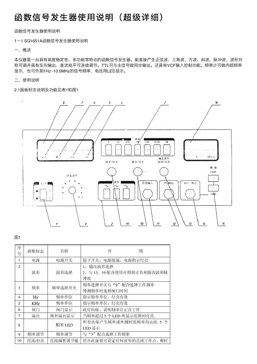
函数信号发⽣器使⽤说明(超级详细)函数信号发⽣器使⽤说明1-1 SG1651A函数信号发⽣器使⽤说明⼀、概述本仪器是⼀台具有⾼度稳定性、多功能等特点的函数信号发⽣器。
能直接产⽣正弦波、三⾓波、⽅波、斜波、脉冲波,波形对称可调并具有反向输出,直流电平可连续调节。
TTL可与主信号做同步输出。
还具有VCF输⼊控制功能。
频率计可做内部频率显⽰,也可外测1Hz~10.0MHz的信号频率,电压⽤LED显⽰。
⼆、使⽤说明2.1⾯板标志说明及功能见表1和图1图1DC1641数字函数信号发⽣器使⽤说明⼀、概述DC1641使⽤LCD显⽰、微处理器(CPU)控制的函数信号发⽣器,是⼀种⼩型的、由集成电路、单⽚机与半导体管构成的便携式通⽤函数信号发⽣器,其函数信号有正弦波、三⾓波、⽅波、锯齿波、脉冲五种不同的波形。
信号频率可调范围从0.1Hz~2MHz,分七个档级,频率段、频率值、波形选择均由LCD显⽰。
信号的最⼤幅度可达20Vp-p。
脉冲的占空⽐系数由10%~90%连续可调,五种信号均可加±10V的直流偏置电压。
并具有TTL电平的同步信号输出,脉冲信号反向及输出幅度衰减等多种功能。
除此以外,能外接计数输⼊,作频率计数器使⽤,其频率范围从10Hz~10MHz(50、100MHz[根据⽤户需要])。
计数频率等功能信息均由LCD显⽰,发光⼆极管指⽰计数闸门、占空⽐、直流偏置、电源。
读数直观、⽅便、准确。
⼆、技术要求2.1函数发⽣器产⽣正弦波、三⾓波、⽅波、锯齿波和脉冲波。
2.1.1函数信号频率范围和精度a、频率范围由0.1Hz~2MHz分七个频率档级LCD显⽰,各档级之间有很宽的覆盖度,如下所⽰:频率档级频率范围(Hz)1 0.1~210 1~20100 10~2001K 100~2K10K 1K ~20K100K 10K ~200K1M 100K ~2M频率显⽰⽅式:LCD显⽰,发光⼆极管指⽰闸门、占空⽐、直流偏置、电源。
仪器使用

扫描/计数
输出波形, 对称性调 节旋钮 函数信号输出 幅度衰减开关
函数信号输 出信号直流 电平预置调 节旋钮
函数信号输出幅 度调节旋钮
输出 波形 选择
使用方法
函数信号输出 50Ω主函数信号输出
1.以终端连接50Ω匹配器的测试电缆,有面板(7)输出信号。 2.由(14)选定输出信号的频段,由(15)调整输出信号频 率值。 3.由(12)选定输出函数的波形。 4.由(11)和(8)选定和调节输出信号的幅度。 5.由(9)选定输出信号所携带的直流电平。 6.旋钮(10)可改变输出脉冲信号空度比,输出波形 为三角或正弦时可使三角波调变为锯齿波,正弦波调 变为正与负半周分别为不同角频率的正弦波,且可移 相180°。
(b)将函数信号发生器输出正弦电压的频率调到1kHz,幅值调到10V峰峰值,输出衰减为 0dB。用示波器测量信号发生器输出电压的峰-峰值。此时,调节Y轴灵敏度选择开关 “V/DIV”,使屏幕上显示的波形幅度适中,则灵敏度选择开关指示的标称值乘上被测信 号 在Y轴方向所占格数就是被测信号的峰-峰值(为保证测量精度,在屏幕上应显示足够高的 波形)。 (C)分别按下函数发生器输出幅度衰减开关“20dB”、”40dB”,记下相应的Y轴灵敏 度选 择开关“V/DIV”所在挡位和屏幕上波形峰-峰所占格数,计算出信号发生器输出电压的 有 (d)用示波器测量交流电压的周期(频率) 对于周期性的被测信号,只要测定一个完 效值。自拟表格记录。 整周期T,则频率f(Hz)=1/T(S)。 将扫描时间微调旋钮顺时针旋到“校准”位置(可听到开关关闭声);若波形不稳 定,可调节“触发电平”,使之稳定。 调节扫描时间粗调旋钮,使显示波形的周期尽可能大。 读取波形一个周期所占格数及扫描速度T/DIV,则被测信号的周期为 T=所占格数X(t/DIV)
信号发生器案例使用说明书

信号发生器工程案例使用说明书V1.0 - 2009.3文档版本 1.0.0文档日期2009年3月第1章概述1.1 案例概述信号发生器工程案例参照“2007年全国大学生电子设计竞赛”高职高专组“信号发生器(H题)”要求设计而成。
根据H题要求,需设计并制作一台信号发生器,使之能产生正弦波、方波和三角波信号,且输出可调。
本工程案例提供的软、硬件设计方案能够完全满足比赛题目中所提到的各项要求。
不仅可作为日常工程训练,还为以后类似比赛题目提供借鉴。
根据设计要求,本案例选用EDA比赛套件中:EDA-SOPC核心板、LCD1602、RS232&PS2及DDS_BOARD四个模块。
电源采用5V直流电源及±5V电源供电。
各模块连接如下图所示:图1.1 各模块连接示意图各模块功能如下:一、由EDA-SOPC核心板提供的FPAG及SDRAM为本系统的核心器件。
主要完成功能:1、采用DDS技术基于FPGA设计信号发生模块,产生要求的信号序列;2、利用SDRAM配合FPGA构成片上系统,建立NIOS控制系统,完成任务调度及人机交互控制。
核心板分别通过相关接口与其它三个功能模块相连。
二、RS232&PS2模块通过8-PIN双排线与核心板的PORT2CP接口相连。
将PS2接口的数字小键盘连接到该模块的PS/2接口上,实现按键输入功能。
三、LCD1602模块通过16-PIN双排线与核心板的PORT12-LCD接口相连。
将液晶LCD1602连接到该模块的液晶接口上,实现人机交互的显示功能。
四、DDS模块分别通过14-PIN双排线与核心板的PORT14-DA接口相连及通过16-PIN双排线与核心板的PORT16-IO接口相连。
该模块实现两路D/A,其中一路产生信号,另一路实现信号幅度的调整,模块的BNC 接头直接输出信号。
注:相关模块的详细功能,可参考该模块说明书。
1.2配件清单EDA-SOPC核心板 1块LCD1602模块 1块RS232&PS2模块 1块DDS_BOARD模块 1块LCD1602液晶 1块PS2接口的数字小键盘 1个5V电源 1个8针接口线 1根14针接口线 1根16针接口线 2根说明书及相关资料 1份快速上手3.1 电路连接按图1.1示意图,将各模块通过双排线连接好。
信号发生器使用说明
Function GeneratorModel : GFG-3015Operation Manual82FG-30150MBiTable of ContentsPage1. Precautions......................................................................................................................... 2 2. Product Introduction.......................................................................................................... 5 3. Features .............................................................................................................................. 6 4. Specifications ..................................................................................................................... 7 5. Front and Rear Panels ..................................................................................................... 10 6. Operation .......................................................................................................................... 18 6.1 The First Step Setup For Instrument .................................................................... 18 6.2 The Setup of Output Function............................................................................... 18 6.3 The Setup of Frequency......................................................................................... 18 6.4 The Setup of Amplitude ......................................................................................... 19 6.5 The Setup of Offset ................................................................................................ 19 6.6 The Setup of Duty................................................................................................... 20 6.7 The Setting of STORE ............................................................................................ 20 6.8 The Setting of RECALL .......................................................................................... 20 6.9 The SHIFT Key and Function Keys ....................................................................... 21 6.10 Setup of LIN or LOG Sweep................................................................................. 21 6.11 Setup of AM Modulation ...................................................................................... 25 6.12 Setup of FM Modulation....................................................................................... 26 6.13 Setup of Trigger.................................................................................................... 28 6.14 Setup of GATE and BURST ................................................................................. 30 6.15 Setup of External Counter ................................................................................... 32 6.16 THE VCF Function ................................................................................................ 34 6.17 THE GCV Output Function................................................................................... 35 6.18 THE TTL Signal Output Function ........................................................................ 36 6.19 THE SYNC Signal Output Function..................................................................... 36 6.20 Remote Control - RS232 Interface ...................................................................... 36 6.21 Commands Syntax ............................................................................................... 38 6.22 The Commands of RS-232 Serial Interface ........................................................ 41 6.23 The Examples of the Communication Interface Software ................................ 44 6.24 The Error message of instrument ....................................................................... 47 7. Adjustment and Correction ............................................................................................. 48 7.1 Preparation.............................................................................................................. 48 7.2 Adjust and Check up the operation DC Voltage.................................................. 48 7.3 Adjusting Main Clock ............................................................................................. 49 7.4 Adjusting Sensitivity of counter ........................................................................... 49 7.5 Adjusting VCF Function 100:1 .............................................................................. 49 7.6 Adjusting Main Frequency , Duty Cycle and GCV Output Check ...................... 49 7.7 Adjusting Rise/Fall Time........................................................................................ 50 7.8 Adjusting Main Sine wave Harmonic Distortion.................................................. 50 7.9 Adjusting Modulation source ................................................................................ 50 7.9.1 Adjusting Rate and symmetry............................................................................ 50 7.9.2 Adjusting Sine wave Harmonic Distortion ........................................................ 51 7.10 Adjusting AM modulation .................................................................................... 51 7.11 Adjusting FM and Sweep Function..................................................................... 53 7.12 Adjusting Trigger Phase ...................................................................................... 55 7.13 Calibrating by Software ....................................................................................... 56 8. The Block Diagram and Description of the System ...................................................... 62iiEC Declaration of ConformityWeGOOD WILL INSTRUMENT CO., LTD.No. 7-1, Jhongsing Rd, Tucheng City,Taipei County 236, TaiwanGOOD WILL INSTRUMENT (SUZHOU) CO., LTD.No. 69, Lushan Road, Suzhou New District Jiangsu, Chinadeclares that the below mentioned productGFG-3015is herewith confirmed to comply with the requirements set out in the Council Directive on the Approximation of the Law of Member States relating to Electromagnetic Compatibility (89/336/EEC, 92/31/EEC, 93/68/EEC) and Low Voltage Equipment Directive (73/23/EEC, 93/68/EEC). For the evaluation regarding the Electromagnetic Compatibility and Low Voltage Equipment Directive, the following standards were applied:◎ EMC EN 61326-1: Electrical equipment for measurement, control and laboratory use –– EMCrequirements (1997+A1: 1998+A2: 2001) Conducted and Radiated Emissions Electrostatic Discharge EN 55011: 1998 class A EN 61000-4-2: 1995+A1:1998 Current Harmonic Radiated Immunity EN 61000-3-2: 2000 EN 61000-4-3: 1996+A1:1998 Voltage Fluctuation Electrical Fast Transients EN 61000-3-3: 1995 EN 61000-4-4: 1995 Surge Immunity ------------------------EN 61000-4-5: 1995 Conducted Susceptibility ------------------------EN 61000-4-6: 1996 Power Frequency Magnetic Field ------------------------EN 61000-4-8 : 1993 Voltage Dips/ Interrupts ------------------------EN 61000-4-11: 1994◎ SafetyLow Voltage Equipment Directive 73/23/EEC & amended by 93/68/EECSafety Requirements IEC/EN 61010-1: 2001GFG-3015p.11. PrecautionsGFG-3015 is specially designed for safety operation. It has passed through rigorous tests of inclement environment to ensure its reliability and good condition. The following precautions are recommended to insure your safety and keep the best condition of the equipment. (1) Safety Terms and Symbols The following terms and symbols may appear in this manual:! !This statement identifies conditions or practices that could result in injury or loss of life. This statement identifies conditions or practices that could CAUTION result in damage to this product or other properties. WARNINGThe following terms and symbols may appear on the product: This term indicates an immediately accessible injury hazard. DANGER This term indicates that an injury hazard may occur, but is WARNING not immediately accessible. This term indicates potential damage to this product or other CAUTION properties.!DANGER High voltage Protective Conductor Terminal ATTENTION refer to manual Double Insulated DANGER Hot surface Earth Ground Terminal(2) Do not place any heavy objects on the instrument under any circumstances.(3) Disassembling the instrument Due to the precision of this instrument, all the procedures of disassembling, adjusting, and maintenance should be performed by a professional technician. If the instrument has to be opened or adjusted under some unavoidable conditions, and to be managed by a technician who is familiar with GFG-3015. Once there is any abnormality, please contact our company or our distributor near you. (4) Power Supply AC input should be within the range of line voltage±15%, 50/60Hz. To prevent the instrument from burning up, be sure to check the line voltage before turning on power.p. 2GFG-3015(5) Grounding!WARNINGTo avoid electrical shock, the power cord protective grounding conductor must be connected to ground.GFG-3015 can be operated only with an earth grounded AC power cord that connects the case and ground well. This is to protect the user and the instrument from the risk of shock hazard. (6) Fuse Replacement!WARNINGFor continued fire protection, replace fuse only with the specific type and rating by qualified personnel. Disconnect the power cord before replacing fuse.The fuse blows only when there is any wrong on the instrument, which will stop working under this situation. Please find out the cause, then open the outside case (Please see the Figure (A), Figure (B) on below) and replace a proper fuse as listed below. Be sure to use the correct fuse before changing the applying location. F101 : T 0.8A/250V F100 : T 0.5A/250V Check the line voltage setting on the rear panel. If the line voltage setting does not match, Please change the line voltage setting according to the following steps: 1. Remove line cord from AC socket. 2. Switch the “AC line voltage switch” to correct setting with flat-blade screwdriver and reinsert.Figure (A) (7) Cleaning the Cabinet Disconnect the AC power cord before cleaning the instrument.Figure (B)Use a soft cloth dampened in a solution of mild detergent and water. Do not spray cleaner directly onto the instrument, since it may leak into the cabinet and cause damage. Do not use chemicals containing benzing, benzne, toluene, xylene, acetone, or similar solvents.GFG-3015p.3(8) Operation environment Indoor use Altitude up to 2000m Temperature to satisfy the specification : Operating temperature : Storage temperature : Relative humidity : Installation category: Pollution degree:18oC ~ 28oC (+64.4oF ~ +82.4oF) 0oC ~ 40oC (+32oF ~ +104oF) -10oC ~ 70oC (+14oF ~ 158oF) up to 90% when 0oC~35oC; up to 70% when 35oC~40oC CAT Ⅱ(The detail is as Table A) 2CAT Ⅳ CAT Ⅲ CAT Ⅱ CAT ⅠTable A For measurements performed at the source of the lowvoltage installation. For measurements performed in the building installation. For measurements performed on circuits directly connected to the low-voltage installation. For measurements performed on circuits not directly connected to Mains.(9) Place GFG-3015 in a location with a suitable environment as stated above free from dust, direct exposition of sunlight, and strong effect of magnetic fields. (10) For United KingdomAs the colours of the wires in mains leads may not correspond with the coloured markings identified in your plug/appliance, proceed as follows: The wire which is coloured Green and Yellow must be connected to the Earth terminal marked with the letter E or by the earth symbol or coloured Green or Green and Yellow. The wire which is coloured Blue must be connected to the terminal which is marked with the letter N or coloured Blue or Black. The wire which is coloured Brown must be connected to the terminal marked with the letter L or P or coloured Brown or Red. If in doubt, consult the instructions provided with the equipment or contact the supplier. This cable/appliance should be protected by a suitably rated and approved HBC mains fuse; refer to the rating information on the equipment and/or user instructions for details. As a guide, cable of 0.75mm2 should be protected by a 3A or 5A fuse. Larger conductorsNOTEThis lead/appliance must only be wired by competent persons.WARNINGTHIS APPLIANCE MUST BE EARTHEDIMPORTANTThe wires in this lead are coloured in accordance with the following codes: Green/Yellow :Earth Blue :Neutral :Live Brownwould normally require 13A types, depending on the connection method used. Any moulded mains connector that requires removal/replacement must be destroyed by removal of any fuse and fuse carrier and disposed of immediately, as a plug with bared wires is hazardous if engaged in a live socket. Any re-wiring must be carried out in accordance with the information detailed in this section.(Phase)p. 4GFG-30152. Product IntroductionThe frequency feedback method applied by GFG-3015 is a new technique that generates stable output frequency with extraordinary accuracy for Function Generator. The traditional function generators typically use integrating circuit and constant current circuit techniques that are easily affected by operation temperature or the quality of resistor or capacitor and other key components to occur poor frequency accuracy. The innovative design for GFG-3015 is to get rid of these problems. The frequency feedback system needs a compatible, powerful frequency counter. GW has designed his own full-function counter chip, GFC-9701, for this system with high frequency test range and full functions, including Period test, Duty test, Ratio test, Time interval, Pulse wide, direct display and direct connect with CPU system. GFG-3015 uses this Chip to read output frequency value at any time. Then CPU will modify the correct value of D/A converter immediately according to this value, so that the user can get a high accuracy frequency from GFG-3015 Function Generator. Besides, the GFG-3015 can also generate a high accuracy frequency to provide high frequency resolution.Graph1 indicates the fundamental construction of a frequency feedback system.D/A ConvertorVCOAMPO/PUser InterfaceCPUCounter (GFC-9701)Except the different design from the typical circuit, GFG-3015 system also has micro controller (CPU unit) equipping an additional RS-232 interface functions which will be used on any test system with other instrument or to be controlled by computer.GFG-3015p.53. FeaturesGFG-3015 is a functional Function generator that applies Frequency feedback control system technique and can generate high frequency accuracy with high resolution. Its main signal source can generate waveforms including sine wave, square wave, triangle wave, and ramp wave. There are additional features listed as follows: All digitized operation user interface Output Waveforms of Sine, Square, Triangle, Ramp, Pulse, AM, FM, Sweep, Trigger and Gate or Burst. Wide output frequency range 0.01Hz ~ 15MHz. High frequency accuracy 0.02% ± 5 count. Maximum frequency resolution 10mHz. Dual displays indicate frequency and amplitude or other necessary information. Built-in 6-digit INT/EXT Function Counter and up to 150MHz frequency range with high resolution. INT/EXT AM/FM Modulation with internal modulation signal output. LIN/LOG Sweep Mode with internal sweep signal output. VCF of 100:1 EXT Frequency Control. SYNC Output. TTL Output. Synchronization GCV Output. Variable DC Offset Control Output Overload Protection RS232 Interface Standardp. 6GFG-30154. SpecificationsOutput Waveforms Sine, Square, Triangle, ± Ramp, Pulse, AM, FM, Sweep, Trigger, Gate or Burst 1.5001MHz ~ 15.0000MHz …(100Hz) 150.01kHz ~ 1.50000MHz…(10Hz) 15.001kHz ~ 150.000kHz…(1Hz) 1.5001kHz ~ 15.0000kHz…(0.1Hz); 150.01Hz ~ 1.50000kHz…(10mHz) 15.01Hz ~ 150.00Hz…(10mHz) 1.51Hz ~ 15.00Hz…(10mHz) 0.01Hz ~ 1.50Hz…(10mHz) 0.02% ±5 CountFrequency Range 10mHz~15MHz in 8 Frequency Range (auto switch)Frequency ResolutionFrequency AccuracyOutput Impedance 50Ω ± 10% Range Amplitude Resolution Accuracy Unit Range DC Offset Resolution Accuracy Control Range Duty Resolution Accuracy Sync Output Sine Impedance Level Distortion 10.00V~0.01V (into 50Ω) 4 amplitude ranges | Vac peak | + | Vdc | < 5V 10mV(10.00V~0.01V) ≤3% ±5count at 10Hz~1MHz ≤10% ±5count at 1MHz~15MHz Vpp, Vrms, dBm ± 5V (into 50Ω) | Vac peak | + | Vdc | < 5V 10mV ≤3% ±3count at Amplitude Min. 80%:20%:80% to 1MHz 1% ≤1% to 1MHz at 50% Duty 50 Ω ±10% >1Vp-p open circuit ≤0.5%(-46dBc) From 10Hz~100kHz ≤-30dBc To 15MHz (Spec. applied form 1Vpp to 10Vpp) ±1% of period + 3ns <18nSec <1% of full scale output at 100HzSquare Triangle and RampAsymmetry Rise or Fall Time Linearity ErrorGFG-3015p.7Sweep ModeSweep Range Sweep Width Rate Sweep output Types Waveform Rate Frequency Range Rate Frequency Accuracy Rate Frequency ResolutionLinear or Log sweep 150kHz~15MHz 15kHz~1.5MHz 1.5kHz~150kHz 150Hz~15kHz 15Hz~1.5kHz 1.5Hz~150Hz 0.15Hz~15Hz 0.01Hz~1.5Hz >100:1(In Same Frequency Range) 0.01Hz~10kHz 0 to≥-5Vp-p into 10k Ω AM, FM, Sweep, Trigger(int/ext), Gate or Burst (Implement by Trigger Type) Sine, Square, Triangle, Ramp or Variable Symmetry Pulse 10mHz~10KHz in 3 Frequency Range (auto switch) 5%±1 countSymmetry Control 90:10:90 ; Resolution:1%10.0kHz~0.1kHz(100Hz) 99Hz~1Hz(1Hz) 0.99Hz~0.01Hz(0.01Hz) Symmetry 90%:10%:90%; Resolution:1% Symmetry Accuracy ±1 count(≤1%) Output Level Modulation Sine Wave Distortion Amplitude Modulation Depth Modulation Frequency Rate Carries -3dB Bandwidth External Sensitivity ≧1Vpp into 10kΩ load ≤2% from 10Hz to 10kHz0~100% 0.01Hz ~ 10kHz(INT) DC~1MHz(EXT) <100Hz to >5MHz ≤10Vpp for 100% modulationFrequency Modulation Deviation 0~±15% Modulation 0.01Hz ~ 10kHz(INT) DC ~ 50kHz(EXT) Frequency Rate External Sensitivity ≤5Vpp for 15% deviationp. 8GFG-3015Start/Stop Phase Range Rate Trigger-90º ~ +80º 0.01Hz~10kHzVCFFrequency Range 0.1Hz ~ 1MHz(Useful to 10MHz) Ext Trig Frequency DC to 1MHz,TTL compatible input level Range Gate or Burst Implement by Trigger setting. 100:1(0 to 10V± 1V) In Same Frequency Range Range Input Linearity <0.5% to 1MHz,<5% to 10MHz Input Impedance 10 k Ω ≧3Vpp LevelTTL Output GCV OutputFan-out >10 TTL Load To set the voltage between 0.2V to 2V as per different Frequency in Same frequency Range INT/EXT Switch Selector Range Accuracy Time Base Resolution Input Impedance Sensitivity 5Hz~150MHz EXT Time Base(10MHz) Accuracy ± 1 count ± 20ppm(23ºC ± 5ºC) after 30 minutes warm up The maximum resolution is 100nHz for 1Hz and 1Hz for 100MHz 1MΩ // 150pF ≤35mVrms(5Hz~100MHz); ≤45mVrms(100MHz~150MHz)Frequency CounterInterface Accessories Power Source Dimensions WeightRS232 GTL-101 × 2, Instruction Manual × 1, Power cord × 1 115/ 230V AC ±15%, Approx. 5kg 50/60Hz 290 (W) × 142 (H) × 346 (D) mmGFG-3015p.95. Front and Rear PanelsFront Panelp. 10GFG-30151POWER button Main Function keys: :Push the button to turn on the power, and the display is activated. Push again the button to turn off the power. Key is to set main output waveform in the cycle of Sine, Triangle and Square. When the key is pressed, the related waveform LEDs will light up accordingly.FUNC2Key is to set main frequency entry mode. Key in the desired value of frequency by using the number keys or Modify keys and Unit keys. When the key is pressed, the FREQ LED (on parameter display area A) will be flashing until other mode is set.FREQKey is to set main amplitude entry mode. Key in the desired value of voltage by using the number keys or Modify keys and Unit keys. When the key is pressed, the AMPL LED (on parameter display area B) will be flashing until other mode is set.AMPLKey is to set main output offset voltage entry mode. Key in the desired value of voltage by using the number keys or Modify keys and Unit keys. When the key is pressed, the OFFS LED (on parameter display area B) will be flashing until other mode is set.OFFSETKey is to set main output Duty Cycle entry mode. Key in the desired value of percentage by using the number keys or Modify keys and Unit keys. When the key is pressed, the DUTY LED (on parameter display area B) will be flashing until other mode is set.DUTY3Modulation/Sweep Function keys:Key is to start performing Amplitude Modulation, Frequency Modulation or Sweep function. When the key is pressed again, the functions will stop. When the key is pressed, the ON/OFF LED (on MOD/SWP Function LED area) will light up, press again the key, the LED will be off. These keys control the functions of sweep and modulation.MOD/ON SOURCEKey is to set Span of Modulation or Sweep entry mode and choose the source of modulation. If set to source choose function, must use Secondary Function mode.SPAN FMKey is to choose the type of modulation between AM and FM. If want to set to FM function, must use Secondary Function mode.AM INT/EXT RATEKey is to set Rate of Modulation, Sweep or Trigger entry mode and choose the signal source of Modulation, Sweep or Trigger. If want to set to signal, must use Secondary Functions mode.GFG-3015p.11STOPKey is to set Start Frequency of Sweep entry mode and Stop Frequency of Sweep entry mode. If set to Stop Frequency of Sweep entry mode, must use Secondary Functions mode.START LOG SKey is to choose the type of Sweep between liner sweep and LOG sweep. If set to LOG sweep, must use Secondary Function mode.LIN S SWP CF SYMKey is to set the Duty cycle of Modulation, Sweep or Trigger source entry mode. Key in the desired value of percentage by using number keys or modify keys and Unit keys. If want to set to center frequency of Sweep function that must use Secondary Functions mode. When the key is pressed, the SYM LED (on parameter display area B) will be flashing until other mode is set. When you use center frequency entry mode then the CF LED (In parameter display area A) will be flashing until other mode is set. The detail operation of these keys. Please refer to the instruction in next Chapter.RECL4System keys:Key is to save or reload the setup parameters of the instrument into or take out from memory; the selected DEFAU numbers is from 0 to 9, up to 10 groups.STORKey is to start performing RS232 interface. Press the key then use rotational knob to change function states (ON or OFF). Press the key again then use rotational knob to change the Baud rate. The cycle order is in 300, 600, 1200, 2400, 4800, 9600 and 19200 sequence. If set the instrument to default state, must use Secondary Function mode. Key is to set the Secondary Functions mode. When the key is pressed, the instrument will choose Secondary Function and the SHIFT LED will light up.SHIFTDEFAU RS232 RS232For example, press SHIFT value of the instrument.5+Hz/Vppcan recall the defaultUnit keys:In ‘Normal’ mode, these keys are used to assign the unit and to set the entered value. For example, you can use dBm and Vpp to set the output amplitude. They can be used to set frequency (MHz, kHz, Hz), OFFSET, and PHASE, etc. In STOR or RECL modes, they are used as ‘Enter’.DEG/% MHz/dBKHz/Vrmsp. 12GFG-30156Entry keys:9 . To and keys are used to input value. A unit key should be pressed to set the entered value. 0key is blank space that used to delete the entered value entirely and the other function is minus key .-/BK SP7Modify keys:Keys are used to change the digit of input value. User can use the Rotate knob for increasing or decreasing that digit.◄ ►Key to terminate the function of all Modify keys until user press this key again. When the key is pressed, the HOLD LED will light up until the key is pressed again.HOLD8Trigger Function keys:Key is to start performing Trigger function mode. If the key is pressed again, the function will stop. When the key is pressed, the ON/OFF LED (In Trigger Function LED area) will light up until the key is pressed again (The LED will light off).TRIG ONKey is to choose the type of Trigger, Single-trigger or multi-trigger. When the key is pressed, the MULT or SINGL LED (In Trigger Function LED area) will light up accordingly.SIGL/MUTKey is to set the phase of trigger function entry mode. Key in the desired value of percentage by using number keys, modify keys and Unit keys. When the key is pressed, the PHASE LED (In parameter display area B) will be flashing until other mode is set.PHASETRIG EXTKey is to choose the Trigger signal source, internal orexternal. When the key is pressed, the EXT LED (In Trigger Function LED area) will light up accordingly until the key is pressed again (The LED will light off).INT/EXT9Counter Function key:10Parameter display Area (A):Key is to set the Gate time of External counter GATE function. The cycle order is according to 0.01s, 0.1s, 1s, and 10s. When the key is pressed, the Gate time LEDs will light up according user’s wish. The other function is to choose input signal source of counter, internal or external, by using Secondary Function mode. The 6-digit Parameter display presents the parameter values and information about the current status and unit. The START LED light on indicated that the value of display was Start frequency of sweep function right now. The STOP LED light on indicated that the value of display was Stop frequency of sweep function right now. The CF LED light on indicated that the value of display was center frequency of sweep function right now.GFG-3015p.1311Parameter display Area (B):121314Waveform Function LEDs Counter Functions LEDs Modulation/Sweep Function LEDs: : :The FREQ LED light on indicated that the value of display was main output frequency right now. The RATE LED light on indicated that the value of display was rate frequency of sweep or modulation or trigger function right now. The SPAN LED light on indicated that the value of display was Span frequency of sweep function right now. The MHz, kHz, Hz and mHz LED light on indicated that unit according current value of display. This 4-digit Parameter display presents the parameter values and information about the current status and unit. The AMPL LED light on indicated that the value of display was main output amplitude right now. The OFFS LED light on indicated that the value of display was main output DC offset voltage right now. The DUTY LED light on indicated that the value of display was main output duty cycle right now. The SPAN LED light on indicated that the value of display was span frequency of modulation function right now. The SYM LED light on indicated that the value of display was modulation signal duty cycle of sweep or modulation or trigger function right now. The PHASE LED light on indicated that the value of display was phase of trigger function right now. The STOR LED light on indicated that the value of display was save group number right now. The RECL LED light on indicated that the value of display was reload group number right now. The V, rms, dBm kHz, Hz, % and DEG LED light on indicated that unit according current value of display. These LEDs indicate the figure of main output waveform and the current operation functions. These LEDs indicate the GATE TIME of external counter and the current value. These LEDs indicate the current status of Sweep and Modulation and the current operation functions. The AM LED lights on to indicate the setting status of amplitude modulation function. The FM LED lights on to indicate the setting status of frequency modulation function. The LIN LED lights on to indicate the setting status of liner sweep function. The LOG LED lights on to indicate the setting status of LOG sweep function. The Sine, Triangle and Square LED light on indicated that according Modulation source waveform. The EXT LED lights on to indicate the external sweep or modulation signal source. The ON/OFF LED lights on to indicate that the sweep or modulation function is enabled.p. 14GFG-3015。
信号源基本操作手册
用户手册SDG1025型函数/任意波形发生器简易操作说明深圳鼎阳科技有限公司基本应用1、前面板说明2、后前面板说明对应数字标识说明如下:○1:10MHz时钟输入接口○2:同步输出接口○3:专用的接地端子○4:【Modulation In】输入接口○5:【EXTTrig/Gate/Fsk/Burst】接口○6:USB Device 接口○7:电源插口3、用户界面①通道显示区②操作菜单区③形显示区④参数显示区4、功能设置简介(1)波形选择设置如下图所示,在操作界面左侧有一列波形选择按键,从上到下分别为正弦波、方波、锯齿波/三角波、脉冲串、白噪声和任意波。
下面对其波形设置逐一进行介绍:使用Sine按键,波形图标变为正弦波,并在状态区左侧出现Sine字样。
本仪器可输出1μHz到50MHz的正弦波形。
设置频率/周期、幅值/高电平、偏移量/低电平、相位,可以得到不同参数的正弦波。
如下图所示,为正弦波的默认设置。
正弦波默认设置界面使用Square 按键,波形图标变为方波,并在状态区左侧出现Square字样。
本仪器可输出1μHz到25MHz并具有可变占空比的方波波形。
设置频率/周期、幅值/高电平、偏移量/低电平、相位、占空比,可以得到不同参数的方波。
如下图所示,为方波的默认设置。
方波默认设置界面使用Ramp 按键,波形图标变为锯齿波/三角波,并在状态区左侧出现Ramp字样。
本仪器可输出1μHz到300KHz的锯齿波/三角波形。
设置频率/周期、幅值/高电平、偏移量/低电平、相位、对称性,可以得到不同参数的锯齿波/三角波。
如下图所示,为锯齿波/三角波的参数设置。
锯齿波/三角波参数设置界面使用Pulse按键,波形图标变为脉冲波信号,并在状态区左侧出现Pulse字样。
本仪器可输出500μHz到10MHz的脉冲波形。
设置频率/周期、幅值/高电平、偏移量/低电平、脉宽/占空比、延时,可以得到不同参数的脉冲波。
如下图所示,为脉冲波的默认设置。
SP1501-1502使用说明书16K

目录第一章概述 (1)1.1 载波频率 (1)1.2 输出电平 (1)1.3 调制 (1)1.4 存储功能 (1)1.5 鞭状天线 (2)1.6 远程控制 (2)第二章技术指标 (3)2.1 载波频率 (3)2.2 射频输出 (3)2.3 调制 (4)2.4 其它 (5)第三章使用说明 (6)3.1 前面板介绍 (6)3.2 后面板介绍 (13)3.3 操作说明 (13)3.3.0 输入状态改变简介 (13)3.3.1 频率输入 (15)3.3.2 电平输入 (17)3.3.3 正弦波输出功能 (19)3.3.4 调幅功能 (19)3.3.5 调频功能 (20)3.3.6 立体声调频功能 (21)3.3.7 地址设置 (24)3.3.8 存储调用 (26)3.3.9 其它功能 (27)第四章附件清单 (28)南京盛普仪器科技有限公司iSP1501/SP1502 是一种CPU控制的高精度的射频信号发生器,频率范围从100kHz 到150MHz或300kHz到300MHz。
除了具有非常好的AM和FM调制功能外,它的输出电平可以0.1dB的步进值变化。
它是专门用于AM/FM 接收机、民用频段电台、无线遥控玩具、无绳电话的研发与生产检测,也可以用于无线电教学实验。
1.1 载波频率SP1501的工作频率范围为100kHz到150MHz,SP1502的工作频率范围为300kHz 到300MHz,用7个LED显示频率。
可以用按键和调节旋钮直接输入载频的频率值,也可以用步进方式输入频率值,还可以用【ΔF】键方便地输入相对某个参考频率的频率偏移。
1.2 输出电平输出电平可以用按键设置或用旋钮以10dB、1 dB、0.1 dB的步进变化,也可以按照设定的步进值进行步进变化。
另外,专用的A、B、C和D电平存储键可以存储和调用4个常用的电平值。
1.3 调制用内部400Hz/1kHz信号或外部信号作为调制源可以产生幅度和频率调制信号。
CA1640-2P使用说明书函数信号发生器的使用1640

按 波 形 分
非正弦波信号发生器
矩形波
锯齿波 阶梯波
钟形波
二、CA1640-2P型函数信号发生器面板认识
LED频率 显示窗口 LED输出电 压显示窗口 幅度调 节旋钮 扫频 宽度
扫频 速率
外测频 率开关 输入端
占空比 开关、 旋钮
TTL 信号 输出
电源开关
频率调 节旋钮 频率范围 选择开关
用于对一般信号源 或其他测量仪器进行校准。
3 校准源
(二)分类
1、按输出信号频率范围分
名称 超低频信号发生器 低频信号发生器 频率范围 1KHz以下 1Hz~1MHz
视频信号发生器
高频信号发生器 超高频信号发生器
20Hz~30MHz
300KHz~300MHz 300MHz以上
2、按输出信号波形划分
TW T 占空比=
T:周期 TW
T TW:脉冲宽 度
作业:
1、简述信号发生器的三个用途。
2、已知频率f=1KHz, 脉冲宽度 TW=0.4mS的矩形波,求该波形的占 空比。
3、 CA1640-2P型函数信号发生器能 输出哪三种信号波形?
顺时针调节此旋钮,增大电压输出幅度; 逆时针调节此旋钮,减小电压输出幅度。
幅度调节 8 旋钮
9
将占空比开关按入,占空比 指示灯亮,调节占空比旋钮, 可改变波形的占空比。
占空比 调节开 关/旋钮
扫频 旋钮
扫频 开关
轻按扫频开关,选择适当扫频信号; 调节速率旋钮,可改变扫频速度;改变 线性/对数开关可产生线性扫频和对数扫频。
扫频/ 计数 功能 选择
波形 选择 开关
衰减 开关
电平调 节开关、 旋钮
- 1、下载文档前请自行甄别文档内容的完整性,平台不提供额外的编辑、内容补充、找答案等附加服务。
- 2、"仅部分预览"的文档,不可在线预览部分如存在完整性等问题,可反馈申请退款(可完整预览的文档不适用该条件!)。
- 3、如文档侵犯您的权益,请联系客服反馈,我们会尽快为您处理(人工客服工作时间:9:00-18:30)。
目录
一、概述 1
二、主要特征 1
三、技术参数 2
函数信号发生器 2 频率计数器 3 其它 3
四、工作原理 3
五、使用说明 4
前面板说明 4 后面板说明 6 测量、试验的准备工作 6 自校检查 6 函数信号输出 6 外测频功能检查7 六、注意事项与检修7
注意事项7 检修7 七、仪器整套设备及附件8
一、概述
本仪器是一种精密的测试仪器,因其具有连续信号、扫频信号、函数信号、脉冲信号,点频正弦信号等多种输出信号和外部测频功能,故定名为SP1641B、SP1642B型函数信号发生器/计数器。
本仪器是电子工程师、电子实验室、生产线及教学、科研需配备的理想设备。
二、主要特征
采用大规模单片集成精密函数发生器电路,使得该机具有很高的可靠性及优良性能/价格比。
采用单片微机电路进行整周期频率测量监控和智能化管理,对于输出信号的频率幅度用户可以直观、准确的了解到(特别是低频时亦是如此)。
因此极大的方便了使用。
该机采用了精密电流电源电路,使输出信号在整个频带内均具有相当高的精度,同时多种电流源的变换使用,使仪器不仅具有正弦波、三角波、方波等基本波形,更具有锯齿波、脉冲波等多种非对称波形的输出,同时对各种波形均可以实现扫描功能。
本机还具有失真度极低的点频正弦信号和TTL电平标准脉冲信号,以及CMOS电平可调的脉冲信号以满足各种试验需要。
机内逻辑电路采用中规模可编程的集成电路设计,优选设计电路,SMT贴片工艺,元件降额使用,全功能输出保护,以保证仪器高可靠性,平均无故障工作时间高达上万小时。
机箱造型美观大方,电子控制按钮操作起来更舒适,更方便。
三、技术参数
位置,对称性调节为“关”位置,整机预热10min。
频率计数器
其它
四、工作原理
如图1所示,整机电路由一片单片机进行管理,主要工作为:控制函数发生器产生的频率;控制输出信号的波形;测量输出的频率或测量外部输入的频率并显示;测量输出信号的幅度并显示。
函数信号由专用的集成电路产生,该电路集成度大,线路简单精度高并易于与微机接口,使得整机指标得到可靠保证。
扫描电路由多片运算放大器组成,以满足扫描宽度、扫描速率的需要。
宽带直流功放电路的选用,保证输出信号的带负载能力以及输出信号的直流电平偏移,均可受面板电位器控制。
整机电源采用线性电路以保证输出波形的纯净性,具有过压、过流、过热保护。
整机前面板布局参见图2
五、使用说明
前面板说明
1、频率显示窗口
显示输出信号的频率或外测频信号的频率。
2、幅度显示窗口
显示函数输出信号的幅度。
3、扫描宽度调节旋钮
调节此电位器可调节扫频输出的频率范围。
在外测频时,逆时针旋到底(绿灯亮),为外输入测量信号经过低通开关进入测量系统。
4、扫描速率调节旋钮
调节此电位器可以改变内扫描的时间长短。
在外测频时,逆时针旋到底(绿灯亮),为外输入测量信号经过衰减“20d B”进入测量系统。
5、扫描/计数输入插座
当“扫描/计数键”(13)功能选择在外扫描状态或外测频功能时,外扫描控制信号或外测频信号由此输入。
6、点频输出端
输出标准正弦波100Hz信号,输出幅度2Vp-p。
7、函数信号输出端
输出多种波形受控的函数信号,输出幅度20Vp-p(1MΩ负载),10Vp-p(50Ω负载)。
8、函数信号输出幅度调节旋钮
调节范围20dB。
9、函数输出信号直流电平偏移调节旋钮
调节范围:-5V~+5V(50Ω负载),-10V~+10V(1MΩ负载)。
当电位器处在关位置时,则为0电平。
10、输出波形对称性调节旋钮
调节此旋钮可改变输出信号的对称性。
当电位器处在关位置时,则输出对称信号。
11、函数信号输出幅度衰减开关
“20dB”、“40dB”键均不按下,输出信号不经衰减,直接输出到插座口。
“20dB”、“40dB”键分别按下,则可选择20dB或40dB 衰减。
“20dB”,“40dB”同时按下时为60dB 衰减。
12、函数输出波形选择按钮
可选择正弦波、三角波、脉冲波输出。
13、“扫描/计数”按钮
可选择多种扫描方式和外测频方式。
14、频率微调旋钮
调节此旋钮可微调输出信号频率,调节基数范围为从<0.1到>1。
15、倍率选择按钮
每按一次此按钮可递减输出频率的1个频段。
16、倍率选择按钮
每按一次此按钮可递增输出频率的1个频段。
17、整机电源开关
此按键揿下时,机内电源接通,整机工作。
此键释放为关掉整机电源。
后面板说明
SP1641B后面板布局参见图3
1、电源插座
交流市电220V输入插座。
内置保险丝容量为0.5A。
2、TTL/CMOS电平调节
调节旋钮,“关”为TTL电平,打开则为CMOS电平,输出幅度可从5V调节到15V。
3、TTL/CMOS输出插座
测量、试验的准备工作
请先检查市电电压,确认市电电压在220V±10%范围内,方可将电源线插头插入本仪器后面板电源线插座内,供仪器随时开启工作。
自校检查函数信号输出
1、在使用本仪器进行测试工作之前,可对其进行自校检查,以确定仪器工作正常与否。
2、自校检查程序(见图4)
50Ω主函数信号输出
1、以终端连接50Ω匹配器的测试电缆,由前面
板插座(7)输出函数信号;
2、由频率选择按钮(15)或(16)选定输出函数信号的频段,由频率微调旋钮调整输出信号频率,直到所需的工作频率值;
3、由波形选择按钮(12)选定输出函数的波形分别获得正弦波、三角波、脉冲波;
4、由信号幅度选择器(11)和(8)选定和调节输出信号的幅度;
5、由信号电平设定器(9)选定输出信号所携带的直流电平;
6、输出波形对称调节器(10)可改变输出脉冲信号空度比,与此类似,输出波形为三角或正弦时可使三角波调变为锯齿波,正弦波调变为正与负半周分别为不同角频率的正弦波形,且可移相180°。
点频正弦信号输出
1、输出标准的正弦波信号,频率为100Hz,幅度为2Vp-p(中心电平为0);
2、以测试电缆(终端不加50Ω匹配器)由输出插座(6)输出。
内扫描信号输出
1、“扫描/计数”按钮(13)选定为内扫描方式;
2、分别调节扫描宽度调节(3)和扫描速率调节
器(4)获得所需的扫描信号输出;
3、函数输出插座(7)、TTL脉冲输出插座均输出
相应的内扫描的扫频信号。
外扫描信号输入
1、“扫描/计数”按钮(13)选定为“外扫描方式”
2、由外部输入插座(5)输入相应的控制信号,即可得到相应的受控扫描信号。
TTL/CMOS电平输出
1、将CMOS电平调节旋钮处于所需位置,以获得所需的电平。
2、输出信号以测试电缆(终端不加50Ω匹配器)从后面板插座(3)输出。
外测频功能检查
1、“扫描/计数”按钮(13)选定为“外计数方式”;
2、用本机提供的测试电缆,将函数信号引入外部输入插座(5),观察显示频率应与“内”测量时相同。
注意事项与检修
注意事项
本仪器采用大规模集成电路,修理时禁用二芯电源线的电烙铁,校准测试时,测量仪器或其他设备的外壳应接地良好,以免意外损坏。
在更换保险丝时严禁带电操作,必须将电源线与交流市电电源切断,以保证人身安全。
维护修理时,一般先排除直观故障,如:断线、碰线、器件倒伏、接插件脱落等可视损坏故障。
然后根据故障现象按工作原理初步分析出故障电路的范围,再以必要的手段来对故障电路进行静态,动态检查,查出确切故障后按实际情况处理,使仪器恢复正常运行。
重大故障及严重损坏与本公司联系或技术咨询或返回工厂修理。
检修
仪器整套设备及附件
SP1641B(或SP1642B)型函数信号发生器/计数器一台测试电缆一根
双夹电缆一根50Ω匹配器(选用件)一只电源线ST3-3 一根备用熔丝管BGXP-1-10-0.5A(已装入插座内)一只产品说明书一本产品合格证一张产品保修证及用户档案卡一份。