Mean Synchronization of Pinning Complex Networks With Linearly ...
Intermittent_Control_for_Fixed-Time_Synchronizatio
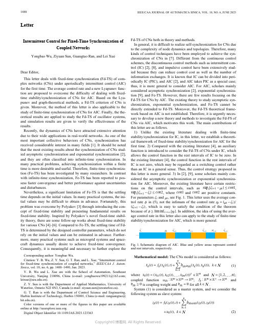
LetterIntermittent Control for Fixed-Time Synchronization ofCoupled NetworksYongbao Wu, Ziyuan Sun, Guangtao Ran, and Lei XueDear Editor,This letter deals with fixed-time synchronization (Fd-TS) of com-plex networks (CNs) under aperiodically intermittent control (AIC) for the first time. The average control rate and a new Lyapunov func-tion are proposed to overcome the difficulty of dealing with fixed-time stability/synchronization of CNs for AIC. Based on the Lya-punov and graph-theoretical methods, a Fd-TS criterion of CNs is given. Moreover, the method of this letter is also applicable to the study of finite-time synchronization of CNs for AIC. Finally, the the-oretical results are applied to study the Fd-TS of oscillator systems, and simulation results are given to verify the effectiveness of the results.Recently, the dynamics of CNs have attracted extensive attention due to their wide applications in real-world networks. As one of the most important collective behaviors of CNs, synchronization has received considerable interest in many fields [1]. It should be noted that the most existing results about the synchronization of CNs stud-ied asymptotic synchronization and exponential synchronization [2], and they are often classified into infinite-time synchronization. In many practical problems, achieving synchronization within a finite time is more desirable and useful. Therefore, finite-time synchroniza-tion (Fe-TS) has been investigated by many researchers. In contrast with infinite-time synchronization, Fe-TS has been reported to pos-sess faster convergence and better performance against uncertainties and disturbances.Nevertheless, a significant limitation of Fe-TS is that the settling time depends on the initial values. In many practical systems, the ini-tial values may be difficult to obtain in advance. Fortunately, this problem was overcome by Polyakov [3] through introducing the con-cept of fixed-time stability and presenting fundamental results on fixed-time stability. Inspired by Polyakov’s novel fixed-time stabil-ity theory, there are some follow-up works about fixed-time stability for various CNs [4]–[6]. Compared to Fe-TS, the settling time of Fd-TS is determined by the designed controller parameters, which do not rely on the initial values and can be estimated in advance. Further-more, many practical systems such as microgrid systems and space-craft dynamics usually desire to achieve fixed-time convergence. Consequently, it is meaningful and necessary to further explore the Fd-TS of CNs both in theory and methods.In general, it is difficult to realize self-synchronization for CNs due to the complexity of node dynamics and topologies. Therefore, many kinds of control techniques have been employed to achieve the syn-chronization of CNs in [7]. Different from the continuous control schemes, the discontinuous control methods such as intermittent con-trol (IC) [2], [8], and impulsive control have been extensively stud-ied because they can reduce control cost as well as the number of information exchanges. It is known that IC can be divided into peri-odically IC (PIC), and AIC [2], and AIC takes PIC as a special case; thus, it is more general to consider AIC. For AIC, scholars mainly considered asymptotic synchronization [2], exponential synchroniza-tion [9], and Fe-TS. However, there are few results focusing on the Fd-TS for CNs by AIC. The existing theory to study asymptotic syn-chronization, exponential synchronization, and Fe-TS cannot be directly extended to Fd-TS. Moreover, the Fd-TS theoretical frame-work based on AIC is not established. Therefore, it is urgently neces-sary to develop a new theory and methods to investigate the Fd-FS of CNs via AIC, which motivates this work. The main contributions of this letter are as follows.sup i{ζi+1−µi}≤con1 sup i{ζi+1−ζi}≤con2con1con2ζiµiϑηi=(µi−ζi)/ (ζi+1−ζi)ϑ≥liminf i→∞{ηi}1) Unlike the existing literature dealing with finite-time stability/synchronization for IC, in this letter, we establish a theoreti-cal framework of fixed-time stability/synchronization for AIC for the first time. 2) Compared with the existing literature [4], an auxiliary function is introduced to consider the Fd-TS of CNs under IC, which allows the control function in the rest intervals of IC to be zero. In the existing literature [4], the control function in the rest intervals of IC is not zero, which may be regarded as a switching control rather than an IC in a general sense. Thus, the control strategy proposed in this letter is more general. 3) In [2], [9], some scholars mainly con-sidered the asymptotic synchronization or exponential synchroniza-tion for AIC. Moreover, the existing literature have certain restric-tions on the control intervals, such as ,, where and are positive constants. For parameters and , see Fig. 1. This letter uses the average con-trol rate in (5), not the infimum of the control rate, which is easy to satisfy the condition of the theorem because of . In addition, the idea of using the aver-age control rate in this letter also can apply to the study of finite-time stability/synchronization for AIC, which is more general.x k(t)=(x k1(t),x k2(t),...,x km(t))αkh:R m×R m→R m f k:R m×R+→R mb kh≥0b kk=0k∈Nwhere and ; coupled function ; and is coupling weight and for all .System (1) is considered as a master system, and we consider theCorresponding author: Yongbao Wu.Citation: Y. B. Wu, Z. Y. Sun, G. T. Ran, and L. Xue, “Intermittent control for fixed-time synchronization of coupled networks,” IEEE/CAA J. Autom. Sinica, vol. 10, no. 6, pp. 1488–1490, Jun. 2023.Y. B. Wu and L. Xue are with the School of Automation, Southeast University, Nanjing 210096, China (e-mail:Z. Y. Sun is with the Department of Applied Mathematics, University of G. T. Ran is with the Department of Control Science and Engineering, Harbin Institute of Technology, Harbin 150001, China (e-mail: ranguangtao@ ).Color versions of one or more of the figures in this paper are available online at .Digital Object Identifier 10.1109/JAS.2023.123363ζiζi+1μi+1μi+2ζi+2ζi+3μi……Fig. 1. Schematic diagram of AIC. Blue and yellow areas represent control and rest intervals, respectively.1488 IEEE/CAA JOURNAL OF AUTOMATICA SINICA, VOL. 10, NO. 6, JUNE 2023z k (t )∈R m u k (t )in which and is an AIC strategy.y k (t )=z k (t )−x k (t )Let be error vector. Based on systems (1) andf k (x k k k (z k k (x k kh (x k k h h )=in which and sign(y k )=diag(sign(y k 1),sign(y k 2),...,sign(y km ))N ={0,1,2,...}[ζi ,µi )[µi ,ζi +1)ζ0=0[y k ]p =(|y k 1|p ,|y k 2|p ,...,|y km |p )T ;ϱs>0(s =1,2,3)q >10<p <1where and ; and stand for the i th control interval and rest interval, respectively; , , , and .f k αkh βk >0φkh >0Assumption 1: Functions and satisfy the Lipschitz condi-tions with Lipschitz constants and , respectively.ϑ∈(0,1)Definition 1 [8]: For AIC strategy (4), there are and con 12[t 2,t 1)ϑT ϑin which stands for the total control interval length on , represents the average control rate, and is called the elasticity number.T (y (0))>0lim t →T (y (0))y (t )=0y (t )≡0t ≥T (y (0))y (t )=(y T 1(t ),y T 2(t ),...,y T n (t ))T T (y (0))y (0)T ∗>0y(0)Definition 2: The master system (1) and slave system (2) are said to achieve Fe-TS, if there is a settling time such that and for , where . The time is called the settling time of syn-chronization, which is dependent of . Especially, if there is a fixed time which is independent of , then systems (1) and (2) achieve the Fd-TS.Analysis of Fd-TS: This section gives two lemmas to study the Fd-TS under AIC (4). Then, a Fd-TS criterion of CNs is given.a 12∗∗in which , , , and Then, whenϑProof: See Section II in the Supplementary material.■iin which , , and If there existsˆa11exp {(1−q )˘εT ϑϑwhere , and are defined in Definition 1.Proof: See Section III in the Supplementary material.■Now, a main result is state as follows.(G ,A )A =(b kh φkh )n ×n ˘ε>0Theorem 1: If the digraph with is stronglyconnected, and there exists satisfying the following inequali-a 33k 44k 3k 1k )−4∑n h =1b kh φkh >0a 4k =2βk +4∑n h =1b kh φkh T ∗in which , , , and , then systems (1)and (2) achieve the Fd-TS, and settling time satisfiesˆa 1=a 1exp {(1−q )˘εT ϑ}a 2=2σmin ϱ2a 1=2σmin ϱ3(mn )1−q2σ1min =min k ∈N {c 1−p2k }σ2min =min k ∈N {c 1−q 2k }c k >0with , , ,, , and can be found in [10].Proof: See Section IV in the Supplementary material.■ϑRemark 1: Theorem 1 requires two inequalities in (8) to be true.We can get that if the average control rate is greater, the condi-tions are easier to meet when other parameters are fixed, which shows that the design of IC has an essential impact on the Fd-TS of CNs.U (t )=exp {Θ(t )}Ψ(t )Θ(t )t ∈[µi ,ζi +1),Remark 2: In the proof of Lemma 2, we use an auxiliary function , where function is defined in Section III-1of the Supplementary material. Moreover, when we can U(t )≤−(˘εϑ−a 4)U (t )[µi ,ζi +1)which enables to be established in the rest intervals . Similar ideas were discussed in semilinear sys-tems [8]. This letter uses the technique to overcome the difficulty of studying Fd-TS of CNs under AIC.sup i {ζi +1−µi }=con 1sup i {ζi +1−ζi }=con 2con 1con 2ηi =(µi −ζi )/(ζi +1−ζi )ϑ≥inf i ∈N {ηi }Remark 3: In Lemma 2, we give a synchronization criterion to achieve the Fd-TS of the systems under AIC for the first time. In the existing results [2], [9], some scholars mainly considered the asymp-totic synchronization or exponential synchronization for IC. More-over, the existing results have certain restrictions on the control and rest intervals, such as , ,where and are positive constants. In this letter, we use the average control rate instead of the infimum of the control rate , which is easier to satisfy the conditions of the theorem because of . In addition, the idea of using an average control rate in this letter also applies to the study of Fe-TS, which is more general. However, as far as we know, no author has considered the general case for Fe-TS under AIC by using the technique of this letter.T ∗ϑT ϑa 1a 2T ∗ϑT ∗Remark 4: We give an important differential inequality (7) in Lemma 2, which can deal with Fd-TS of CNs for AIC. Moreover, the fixed time depends on the average control rate and elasticity number . In addition, we find that the larger parameters and in (7), the smaller the fixed time . And when the average control rate is greater, the settling time will be smaller.Remark 5: Recently, some scholars have considered the Fd-TS for CNs under AIC [4]. For the IC, this letter allows the control function in the rest intervals of the IC to be zero. In the existing results [4], the control function in the rest intervals of IC is not zero, which may be regarded as a switching control. In addition, the average control rate of AIC is considered, which provides less conservative results.Application and numerical simulations: See Section IV in the Supplementary material.Conclusions: We considered the Fd-TS of CNs under AIC. The average control rate and a new Lyapunov function were proposed to overcome the difficulty of dealing with fixed-time stability/synchro-nization of CNs for AIC. Meanwhile, a Fd-TS criterion of CNs was given. Finally, we applied the theoretical results to study the Fd-TS of oscillator systems, and simulation results were given to verify the effectiveness of the results. Considering the influence of the delay factor, the Fd-TS of delayed CNs under AIC will be studied in the future.Acknowledgments: This work was supported in part by the Natu-ral Science Foundation of Jiangsu Province of China (BK20220811,BK20202006); the National Natural Science Foundation of China (62203114, 62273094); the Fundamental Research Funds for the Central Universities, and the “Zhishan” Scholars Programs of South-WU et al .: INTERMITTENT CONTROL FOR FD-TS OF CNS 1489east University; China Postdoctoral Science Foundation (2022M 710684); and Excellent Postdoctoral Foundation of Jiangsu Provinceof China (2022ZB116).Supplementary material: The supplementary material of this let-ter can be found in links https:///est/d3296793221015/pdf.ReferencesF. Dörfler and F. Bullo, “Synchronization in complex networks of phaseoscillators: A survey,” Automatica , vol. 50, no. 6, pp. 1539–1564, 2014.[1]X. Liu and T. Chen, “Synchronization of complex networks viaaperiodically intermittent pinning control,” IEEE Trans. Automatic Control , vol. 60, no. 12, pp. 3316–3321, 2015.[2]A. Polyakov, “Nonlinear feedback design for fixed-time stabilization oflinear control systems,” IEEE Trans. Automatic Control , vol. 57, no. 8,pp. 2106–2110, 2011.[3]Q. Gan, F. Xiao, and H. Sheng, “Fixed-time outer synchronization ofhybrid-coupled delayed complex networks via periodically semi-intermittent control,” J. Franklin Institute , vol. 356, no. 12, pp. 6656–6677, 2019.[4]J. Liu, Y. Wu, M. Sun, and C. Sun, “Fixed-time cooperative tracking fordelayed disturbed multi-agent systems under dynamic event-triggered control,” IEEE/CAA J. Autom. Sinica , vol. 9, no. 5, pp. 930–933, 2022.[5]Z. Zuo, B. Tian, M. Defoort, and Z. Ding, “Fixed-time consensustracking for multiagent systems with high-order integrator dynamics,”IEEE Trans. Autom. Control , vol. 63, no. 2, pp. 563–570, 2018.[6]W. Yu, P. DeLellis, G. Chen, M. Di Bernardo, and J. Kurths,“Distributed adaptive control of synchronization in complex networks,”IEEE Trans. Autom. Control , vol. 57, no. 8, pp. 2153–2158, 2012.[7]Y. Guo, M. Duan, and P. Wang, “Input-to-state stabilization ofsemilinear systems via aperiodically intermittent event-triggered control,” IEEE Trans. Control Network Syst., vol. 9, no. 2, pp. 731–741, 2022.[8]Y. Wu, S. Zhuang, and W. Li, “Periodically intermittent discreteobservation control for synchronization of the general stochastic complex network,” Automatica , vol. 110, p. 108591, 2019.[9]M. Y. Li and Z. Shuai, “Global-stability problem for coupled systems ofdifferential equations on networks,” J. Differential Equations , vol. 248,no. 1, pp. 1–20, 2010.[10] 1490IEEE/CAA JOURNAL OF AUTOMATICA SINICA, VOL. 10, NO. 6, JUNE 2023。
多用户MIMO-MEC网络中基于APSO的任务卸载研究

多用户MIMO-MEC网络中基于APSO的任务卸载研究顾敏;徐雅男;王辛迪;花敏;周雯【期刊名称】《无线电工程》【年(卷),期】2024(54)3【摘要】在移动边缘计算(Mobile Edge Computing,MEC)系统中引入多输入多输出(Multiple Input Multiple Output,MIMO)技术与数据压缩技术,能够降低数据冗余度和提高数据传输速率,从而降低任务的执行时延与能耗。
针对具备数据压缩功能的多用户MIMO-MEC网络,研究了多用户任务卸载问题。
通过联合优化任务卸载比例、数据压缩比例、发送功率、计算频率和信道带宽,来最小化系统总时延。
在能耗、功率和带宽等约束条件下,将任务卸载归纳为一个非凸优化问题。
由于能耗约束较为复杂,构造罚函数将其归并,得到一个相对简单的等价问题。
将所有优化变量视为一个粒子,基于自适应粒子群优化(Adaptive Particle Swarm Optimization,APSO)框架提出多用户的任务卸载方法。
由于粒子更新时可能违反约束条件,提出的方法对粒子越界的情形进行了特别处理。
该方法能自适应地调整惯性权重来提高寻优能力和收敛性,通过不断迭代最终获得最优或者次优解。
仿真实验评估了所提卸载方法的性能,分析了用户数、任务计算强度等参数对系统性能的影响。
结果表明,提出的方法优于本地计算、传统粒子群优化(Particle Swarm Optimization,PSO)算法等对比方案,能够有效降低系统的任务执行时延。
【总页数】8页(P711-718)【作者】顾敏;徐雅男;王辛迪;花敏;周雯【作者单位】南京林业大学信息科学技术学院;安徽大学互联网学院【正文语种】中文【中图分类】TN929.5;TP18【相关文献】1.基于延迟接受的多用户任务卸载策略2.基于稳定匹配的多用户任务卸载策略3.基于深度强化学习多用户移动边缘计算轻量任务卸载优化4.基于深度强化学习的多用户边缘计算任务卸载调度与资源分配算法5.基于博弈论的多服务器多用户视频分析任务卸载算法因版权原因,仅展示原文概要,查看原文内容请购买。
pull down buffer经典配方
Arabidopsis EPSIN1Plays an Important Role in VacuolarTrafficking of Soluble Cargo Proteins in Plant Cells via Interactions with Clathrin,AP-1,VTI11,and VSR1WJinhee Song,Myoung Hui Lee,Gil-Je Lee,Cheol Min Yoo,and Inhwan Hwang1Division of Molecular and Life Sciences and Center for Plant Intracellular Trafficking,Pohang University of Scienceand Technology,Pohang790-784,KoreaEpsin and related proteins play important roles in various steps of protein trafficking in animal and yeast cells.Many epsin homologs have been identified in plant cells from analysis of genome sequences.However,their roles have not been elucidated.Here,we investigate the expression,localization,and biological role in protein trafficking of an epsin homolog, Arabidopsis thaliana EPSIN1,which is expressed in most tissues we examined.In the cell,one pool of EPSIN1is associated with actinfilaments,producing a network pattern,and a second pool localizes primarily to the Golgi complex with a minor portion to the prevacuolar compartment,producing a punctate staining pattern.Protein pull-down and coimmunoprecipitation experiments reveal that Arabidopsis EPSIN1interacts with clathrin,VTI11,g-adaptin-related protein(g-ADR),and vacuolar sorting receptor1(VSR1).In addition,EPSIN1colocalizes with clathrin and VTI11.The epsin1mutant,which has a T-DNA insertion in EPSIN1,displays a defect in the vacuolar trafficking of sporamin:greenfluorescent protein(GFP),but not in the secretion of invertase:GFP into the medium.Stably expressed HA:EPSIN1complements this trafficking defect.Based on these data,we propose that EPSIN1plays an important role in the vacuolar trafficking of soluble proteins at the trans-Golgi network via its interaction with g-ADR,VTI11,VSR1,and clathrin.INTRODUCTIONAfter translation in eukaryotic cells,a large number of proteins are transported to subcellular compartments by a variety of different mechanisms.Newly synthesized vacuolar proteins that are delivered to the endoplasmic reticulum(ER)by the cotrans-lational translocation mechanism are transported to the vacuole from the ER by a process called intracellular trafficking.Traffick-ing of a protein to the vacuole from the ER occurs through two organelles,the Golgi complex and the prevacuolar compartment (PVC)(Rothman,1994;Hawes et al.,1999;Bassham and Raikhel, 2000;Griffiths,2000).Transport of a protein from the ER to the Golgi complex is performed by coat protein complex II vesicles. Transport from the trans-Golgi network(TGN)to the PVC occurs via clathrin-coated vesicles(CCVs)(Robinson et al.,1998;Tang et al.,2005;Yang et al.,2005).Transport of a protein from the ER to the vacuole/lysosome requires a large number of proteins,including components of vesicles,factors involved in vesicle generation and fusion,reg-ulators of intracellular trafficking,adaptors for the cargo proteins, and other accessory proteins(Robinson and Kreis,1992;Bennett, 1995;Schekman and Orci,1996;da Silva Conceic¸a˜o et al.,1997;Kirchhausen,1999;Sever et al.,1999;Bassham and Raikhel, 2000;Griffiths,2000;Jin et al.,2001;Robinson and Bonifacino, 2001).Most of these proteins are found in all eukaryotic cells from yeast,animals,and plants,suggesting that protein traffick-ing mechanisms from the ER to the vacuole/lysosome may be highly conserved in all eukaryotic cells.Of the large number of proteins involved in intracellular traf-ficking,a group of proteins that have the highly conserved epsin N-terminal homology(ENTH)domain have been identified as playing a critical role at various trafficking steps in animal and yeast cells(Chen et al.,1998;De Camilli et al.,2002;Wendland, 2002;Overstreet et al.,2003;Legendre-Guillemin et al.,2004). The ENTH domain binds to phosphatidylinositols(PtdIns), although the lipid binding specificity differs with individual members of the epsin family.For example,epsin1binds to PtdIns(4,5)P2,whereas EpsinR and Ent3p bind to PtdIns(4)P and PdtIns(3,5)P2,respectively(Itoh et al.,2001).The ENTH domain is thought to be responsible for targeting these proteins to specific compartments and also for introducing curvature to the bound membranes to assist in the generation of CCVs(Legendre-Guillemin et al.,2004).However,the exact steps of intracellular trafficking in which ENTH-containing proteins play a role are complex.Epsin homologs can be divided into two groups based on the pathway in which they play a role.One group,which includes epsin1in animal cells and Ent1p and Ent2p in yeast cells,is involved in endocytosis from the plasma membrane (Chen et al.,1998;De Camilli et al.,2002;Wendland,2002).The other group,which includes EpsinR/clint/enthoprotin in animal cells and Ent3p and Ent4p in yeast cells,is involved in protein trafficking from the TGN to the lysosome/vacuole as well as1To whom correspondence should be addressed.E-mail ihhwang@postech.ac.kr;fax82-54-279-8159.The author responsible for distribution of materials integral to thefindings presented in this article in accordance with the policy describedin the Instructions for Authors()is:Inhwan Hwang(ihhwang@postech.ac.kr).W Online version contains Web-only data./cgi/doi/10.1105/tpc.105.039123The Plant Cell,Vol.18,2258–2274,September2006,ª2006American Society of Plant Biologistsretrograde trafficking from the early endosomes to the TGN (Kalthoff et al.,2002;Wasiak et al.,2002;Hirst et al.,2003; Chidambaram et al.,2004;Eugster et al.,2004;Saint-Pol et al., 2004).Another common feature of epsin-related proteins is that they play a role in CCV-mediated protein trafficking at both the TGN and the plasma membrane.These proteins can bind directly to clathrin through their multiple clathrin binding motifs;thus,they may recruit clathrin to the plasma membrane or the TGN to generate CCVs(Rosenthal et al.,1999;Wendland et al.,1999; Drake et al.,2000).In addition,these proteins interact with many other proteins,such as heterotetrameric clathrin adaptor complexes(APs),monomeric adaptor Golgi-localized,g-ear–containing Arf binding proteins(GGAs),and soluble NSF attach-ment protein receptors(SNAREs).Epsin1interacts with AP-2, Epsin15,and intersectin(Chen et al.,1998;Legendre-Guillemin et al.,2004),whereas EpsinR/enthoprotin/clint and Ent3p interact with SNAREs such as vti1b and vti1p,respectively (Chidambaram et al.,2004)and with adaptor proteins such as GGAs and AP-1(Duncan et al.,2003;Mills et al.,2003).In addition,epsin homologs have ubiquitin-interacting motifs and are ubiquitinated(Oldham et al.,2002;Shih et al.,2002).Protein ubiquitination acts as a signal for endocytosis from the plasma membrane and trafficking from the TGN through the endosome/ PVC to the lysosome/vacuole(Polo et al.,2002;Horak,2003; Raiborg et al.,2003;Scott et al.,2004).The binding of epsin homologs to ubiquitin raises the possibility that epsin homologs may bind directly to cargo proteins that are destined for the vacuole/lysosome from either the plasma membrane or the TGN (Chen and De Camilli,2005;Sigismund et al.,2005).In plant cells,sequence analysis of the entire Arabidopsis thaliana genome reveals several proteins with the highly con-served ENTH domains(Holstein and Oliviusson,2005).However, their biological roles have not been addressed.In this study,we investigate the functional role of EPSIN1,an Arabidopsis epsin homolog,at the molecular level.In particular,we focus on its possible role in protein trafficking in plant cells.We demonstrate that EPSIN1interacts with clathrin,AP-1,VSR1,and VTI11and plays an important role in the vacuolar trafficking of a soluble protein from the Golgi complex to the central vacuole.RESULTSEPSIN1,a Member of the Epsin Family,Is Ubiquitously Expressed in ArabidopsisThe Arabidopsis genome encodes three highly similar epsin-related proteins,EPSIN1,EPSIN2,and EPSIN3(Holstein and Oliviusson,2005).In this study,we investigated the biological role of EPSIN1.EPSIN1has the highly conserved ENTH domain at the N terminus.However,the rest of the molecule is less similar to other epsin-related proteins,although it has motifs,such as LIDL and DPF,that may function as clathrin and AP-1binding motifs,respectively.To understand the biological role of EPSIN1,its expression in various plant tissues was examined.An antibody was raised against the middle domain of EPSIN1(amino acid residues153to 337).The antibody recognized a protein band at90kD,which was much larger than the expected size,60kD,of EPSIN1 (Figure1A).It was shown previously that epsin-related proteins migrate slower than expected in SDS-PAGE(Chen et al.,1998). The control serum did not recognize any protein bands.This re-sult suggested that the antibody specifically recognized EPSIN1. To confirm this,protoplasts were transformed with EPSIN1 tagged with HA at the N terminus(HA:EPSIN1)and protein extracts from the transformed protoplasts were analyzed by protein gel blotting using anti-HA and anti-EPSIN1antibodies. The anti-HA antibody specifically recognized a protein band from the transformed protoplasts,but not from the untransformed protoplasts,at90kD(Figure1B).In addition,the90-kD protein species was recognized by the anti-EPSIN1antibody,confirming that the90-kD band was EPSIN1.The expression of EPSIN1in various tissues was examined using the anti-EPSIN1antibody. Protein extracts were prepared from various tissues at different stages of plant growth and used for protein gel blot analysis. EPSIN1was expressed in all of the tissues examined,with the highest expression in cotyledons andflowers(Figure1C). EPSIN1Produces Both Network and PunctateStaining PatternsTo examine the subcellular distribution of EPSIN1,total protein extracts from leaf tissues were separated into soluble and membrane fractions and analyzed by protein gel blotting using anti-EPSIN1antibody.EPSIN1was detected in both membrane (pellet)and soluble fractions(Figure2A).As controls for the fractionation,Arabidopsis aleurain-like protease(AALP)and Arabi-dopsis vacuolar sorting receptor(VSR)were detected with anti-AALP and anti-VSR antibodies,respectively(Sohn et al.,2003). AALP is a soluble protein present in the vacuolar lumen,and VSR is a membrane protein that is localized primarily to the PVC with a minor portion to the Golgi complex(da Silva Conceic¸a˜o et al., 1997;Ahmed et al.,2000).As expected,AALP and VSR were detected in the supernatant and pellet fractions,respectively. These results indicated that EPSIN1localized to multiple loca-tions,consistent with the behavior of other epsin-related proteins (Legendre-Guillemin et al.,2004).Next,we defined the subcellular localization of EPSIN1.Our initial attempts to localize the endogenous EPSIN1with the anti-EPSIN1antibody failed.Thus,we determined the localization of EPSIN1protein transiently expressed in protoplasts.EPSIN1 was tagged with the HA epitope,greenfluorescent protein(GFP), or redfluorescent protein(RFP).The amount of total EPSIN1 protein was determined using various amounts of HA:EPSIN1 plasmid DNA by protein gel blot analysis with anti-EPSIN1an-tibody and was found to be proportional to the amount of plasmid used(Figure2B).For the localization,we used a minimal amount(5to10m g)of EPSIN1plasmid DNAs.Protoplasts were transformed with HA:EPSIN1,and localization of EPSIN1 was determined by immunostaining with anti-HA antibody.HA: EPSIN1produced primarily a punctate staining pattern(Figure 2Ca).In addition to punctate stains,we occasionally observed weakly stained strings that connected punctate stains(Figure 2Cc,arrowheads).By contrast,the nontransformed controls did not produce any patterns(Figure2Ce).In protoplasts trans-formed with EPSIN1:GFP and EPSIN1:RFP,both EPSIN1fusionEPSIN1in Vacuolar Trafficking2259proteins produced a network pattern with punctate stains (Fig-ures 2Cg and 2Ch),whereas GFP and RFP alone produced diffuse patterns (Figures 2Dh and 2Di),indicating that EPSIN1produces the network pattern with punctate stains.These results were further confirmed by cotransforming the protoplasts with either EPSIN1:GFP and HA:EPSIN1or EPSIN1:GFP and EPSIN1:RFP .The punctate staining pattern of EPSIN1:GFP closely over-lapped that of HA:EPSIN1(Figures 2Da to 2Dc).In addition,the network and punctate staining patterns of EPSIN1:GFP closely overlapped those of EPSIN1:RFP (Figures 2De to 2Dg).However,the fine networks revealed by EPSIN1:GFP in the live protoplasts were nearly absent in the fixed protoplasts.Thus,the differences in the staining patterns between fixed and live protoplasts may be attributable to the fact that the network pattern of live protoplasts are not well preserved under the fixing conditions used.In addi-tion,the strings occasionally observed in the fixed protoplasts may represent the remnants of the network pattern revealed by HA:EPSIN1.These results strongly suggest that EPSIN1is re-sponsible for the network pattern as well as the punctate stains.The network pattern was reminiscent of the ER or actin pattern in plant cells (Boevink et al.,1998;Jin et al.,2001;Kim et al.,2005),whereas the punctate staining pattern suggested that EPSIN1may localize to the Golgi complex or endosomes,as observed previously with epsin homologs in animal and yeast cells (Wasiak et al.,2002;Chidambaram et al.,2004;Saint-Pol et al.,2004).Therefore,protoplasts were cotransformed with EPSIN1:RFP and GFP:talin ,a marker for actin filaments consist-ing of GFP and the actin binding domain of mouse talin (Kost et al.,1998;Kim et al.,2005).As expected,GFP:talin produced the network pattern (Figure 3A)(Kost et al.,1998;Kim et al.,2005).Furthermore,the red fluorescent network pattern of EPSIN1:RFP closely overlapped the green fluorescent network pattern of GFP:talin (Figure 3A),raising the possibility that EPSIN1:GFP bound to the actin filaments rather than to the ER.To confirm this,the EPSIN1:RFP pattern was examined after treatment with latrunculin B (Lat B),a chemical agent known to disrupt actin filaments (Spector et al.,1983).Lat B–treated protoplasts produced the diffuse green fluorescent pattern of GFP:talin (Figure 3A),an indication of solubilized actin filaments,as observed previously (Kim et al.,2005).In addition,the Lat B–treated protoplasts displayed a diffuse red fluorescent pattern of EPSIN1:RFP (Figure 3A),indicating that EPSIN1is associated with actin filaments but not with the ER.Furthermore,the punc-tate staining pattern of EPSIN1:RFP also was not observed in the presence of Lat B,indicating that actin filaments played a role in yielding the punctate staining pattern of EPSIN1.In the same conditions,BiP:GFP,an ER marker (Lee et al.,2002),produced a network pattern,indicating that Lat B does not disrupt the ER network patterns (Figure 3Ai).To identify the organelle responsible for the punctate staining pattern of EPSIN1,its localization was compared with that of ST:GFP and PEP12p/SYP21.ST:GFP,a chimericproteinFigure 1.EPSIN1Is Expressed in Various Arabidopsis Tissues.(A)Generation of anti-EPSIN1antibody.The middle domain,corresponding to amino acid residues 153to 337,was expressed as the Hisx6-tagged form in E.coli and used to raise antibody in a rabbit.Control serum was obtained from the rabbit before immunization.Total protein extracts were obtained from leaf tissues and used to test the anti-EPSIN1antibody.(B)Specificity of the anti-EPSIN1antibody.Protein extracts were obtained from protoplasts expressing EPSIN1tagged with the HA epitope at the N terminus and used for protein gel blot analysis using anti-HA and anti-EPSIN1antibodies.(C)Expression of EPSIN1in various tissues.Total protein extracts from the indicated tissues were analyzed by protein gel blotting using anti-EPSIN1antibody.Leaf tissues were harvested 11and 20d after germination.Cotyledons were obtained from 5-d-old plants.The membranes were stained with Coomassie blue to control for protein loading.RbcL,large subunit of the ribulose-1,5-bis-phosphate carboxylase/oxygenase (Rubisco)complex.2260The Plant CellFigure 2.EPSIN1Produces Both Network and Punctate Staining Patterns.(A)Subcellular fractionation of EPSIN1.Total (T)protein extracts of leaf tissues were separated into soluble (S)and pellet (P)fractions and analyzed by protein gel blotting using anti-EPSIN1,anti-AALP,and anti-VSR antibodies.(B)Expression level of EPSIN1in transformed protoplasts.Protoplasts were transformed with various amounts of HA:EPSIN1DNA,and the level of EPSIN1was determined by protein gel blotting with anti-EPSIN1antibody.Protein extracts from untransformed protoplasts were used as a control.The membrane was also stained with Coomassie blue to control for loading.(C)Localization of EPSIN1.Protoplasts were transformed with the indicated constructs (5to 10m g),and the localization of EPSIN1was examined either by immunostaining with anti-HA antibody or by direct detection of the GFP or RFP signal.Untransformed protoplasts were immunostained with anti-HA antibody as a control.Bars ¼20m m.(D)Colocalization of EPSIN1proteins.The localization of EPSIN1protein was examined in protoplasts transformed with HA:EPSIN1and EPSIN1:GFP or with EPSIN1:GFP and EPSIN1:RFP .As controls,GFP and RFP alone were transformed into protoplasts.Bars ¼20m m.EPSIN1in Vacuolar Trafficking 2261亚细胞定位可以荧光观察也可以做western 检测Figure 3.Localization of EPSIN1in Protoplasts.2262The Plant Cellbetween rat sialyltransferase and GFP,localizes to the Golgi complex,and PEP12p,a t-SNARE,localizes to the PVC(da Silva Conceic¸a˜o et al.,1997;Boevink et al.,1998;Jin et al.,2001). Protoplasts were cotransformed with HA:EPSIN1and ST:GFP. The localization of these proteins was examined after staining with anti-HA antibody.ST:GFP was observed directly with the greenfluorescent signals.A major portion of the HA:EPSIN1-positive punctate stains closely overlapped with those of ST:GFP (Figures3Ba to3Bc).To further confirm the Golgi localization of HA:EPSIN1,protoplasts transformed with HA:EPSIN1were treated with brefeldin A(BFA),a chemical known to disrupt the Golgi complex(Driouich et al.,1993),and the localization of HA:EPSIN1was examined.In the presence of BFA,HA:EPSIN1 yielded a largely diffuse pattern with aggregates,but not the punctate staining pattern,indicating that BFA affects EPSIN1 localization(Figure3Be).In the same conditions,ST:GFP pro-duced a network pattern with large aggregates(Figure3Bg), confirming that the Golgi complex was disrupted.These results support the notion that EPSIN1localizes to the Golgi complex. Next,we examined the possibility of EPSIN1localizing to the PVC.Protoplasts were cotransformed with EPSIN1:GFP and PEP12p:HA.The localization of PEP12p:HA was examined after staining with anti-HA antibody.EPSIN1:GFP was observed di-rectly with the greenfluorescent signals.Only a minor portion of the EPSIN1:GFP-positive punctate stains overlapped with the PEP12p:HA-positive punctate stains(Figures3Bi to3Bk,ar-rows).These results indicated that EPSIN1localized primarily to the Golgi complex with a minor portion to the PVC.To obtain independent evidence for the localization,we ex-amined the colocalization of EPSIN1with VTI11,a v-SNARE that is distributed equally to both the TGN and the PVC(Zheng et al., 1999;Bassham et al.,2000;Kim et al.,2005).Protoplasts were cotransformed with EPSIN1:GFP and VTI11:HA,and the local-ization of these proteins was examined by immunostaining with anti-HA antibody.EPSIN1-positive punctate stains largely colo-calized with those of VTI11:HA(Figures3Bm to3Bo),confirming that EPSIN1localizes to both the Golgi complex and the PVC. EPSIN1Binds to and Colocalizes with ClathrinThe members of the epsin family have two clathrin binding motifs (Rosenthal et al.,1999;Wendland et al.,1999;Drake et al.,2000). Sequence analysis indicated that EPSIN1has a potential clathrin binding motif.To explore the possibility that EPSIN1binds to clathrin,glutathione S-transferase–fused EPSIN1(GST:EPSIN1) was constructed for a protein pull-down assay(Figure4A).GST: EPSIN1was expressed in Escherichia coli and purified from E. coli extracts(Figure4B).The purified GST:EPSIN1was mixed with protein extracts obtained from leaf tissues.Proteins pelleted with glutathione–agarose were analyzed by protein gel blotting using anti-clathrin antibody.GST:EPSIN1,but not GST alone, precipitated from the plant extracts a180-kD protein species that was recognized by anti-clathrin antibody(Figure4C),indi-cating that EPSIN1bound to clathrin.To further examine its binding to clathrin,EPSIN1was divided into two regions,the ENTH and the remainder of the molecule (EPSIN1D N)(Figure4A).These regions were expressed in E.coli as GST fusion proteins,GST:ENTH and GST:EPSIN1D N,re-spectively(Figure4B).Protein pull-down experiments using leaf cell extracts were performed with purified GST:ENTH and GST: EPSIN1D N.GST:EPSIN1D N,but not GST:ENTH,precipitated clathrin from the plant extracts(Figure4C).To identify the clathrin binding motif,the C-terminal region containing the putative clathrin binding motif,LIDL(Lafer,2002),as well as GST:RIDL, which contained an Arg substitution of thefirst Leu residue in the motif,were expressed as GST fusion proteins in E.coli(Figures 4A and4B).GST:LIDL,but not GST:RIDL,precipitated clathrin from protein extracts(Figure4C),indicating that the LIDL motif functioned as a clathrin binding motif.The in vitro binding of EPSIN1with clathrin strongly suggested that EPSIN1was likely to colocalize with clathrin.Therefore, immunohistochemistry for the localization of EPSIN1and clathrin was performed.Protoplasts were transformed with HA:EPSIN1, and the localization of HA:EPSIN1and clathrin was examined by staining with anti-HA and anti-clathrin antibodies,respectively. The anti-clathrin antibody produced a punctate staining pattern (Figure4D).A majority(60to70%)of the HA:EPSIN1-positive punctate stains closely overlapped with a pool(40to50%)of clathrin-positive punctate stains(Figure4D),consistent with an interaction between EPSIN1and clathrin.There was also a pool of clathrin-positive punctate stains that lacked the HA:EPSIN1 signal,suggesting that clathrin also was involved in an EPSIN1-independent process.To further characterize the interaction between EPSIN1and clathrin,we examined whether or not EPSIN1is permanently associated with CCVs.Protein extracts from leaf tissues were first separated into soluble and pellet fractions by ultracentrifu-gation.The pellet fraction was treated with Triton X-100and further fractionated by gelfiltration,and the fractions were ana-lyzed by protein gel blotting using anti-clathrin,anti-EPSIN,and anti-VSR antibodies.Clathrin was detected in a peak between 443and669kD(see Supplemental Figure1online).Interestingly, VSR,the vacuolar cargo receptor,was eluted at the same posi-tion with clathrin.By contrast,EPSIN1was eluted at90kD. These results suggest that EPSIN1is not permanently associ-ated with CCVs.Figure3.(continued).(A)Colocalization of EPSIN1with actinfilaments.Protoplasts were transformed with the indicated constructs,and the localization of these proteins was examined in the presence(þLat B)and absence(ÿLat B)of Lat B(10m M).Bars¼20m m.(B)Localization of EPSIN1to the Golgi complex and the PVC.Protoplasts were transformed with the indicated constructs,and localization of the proteins was examined after immunostaining with anti-HA.The GFP signals were observed directly in thefixed protoplasts.For BFA treatment,BFA(30 m g/mL)was added to the transformed protoplasts at24h after transformation and incubated for3h.Arrows indicate the overlap between EPSIN1:GFP and PEP12p:HA.Bars¼20m m.EPSIN1in Vacuolar Trafficking2263Figure 4.EPSIN1Binds to and Colocalizes with Clathrin.(A)Constructs.GST was fused to the N terminus.ENTH,the epsin N-terminal homology domain.DLF and DPF motifs are similar to AP-1and AP-3binding motifs,respectively.Q11indicates a stretch of 11Glu residues.The clathrin binding motif (LIDL)and the Leu-to-Arg substitution in the clathrin binding motif (RIDL)are shown in the C-terminal region.The numbers indicate amino acid positions.(B)Expression of GST-fused EPSIN1proteins.Constructs were introduced into E.coli ,and their expression was induced by isopropylthio-b -galactoside.GST fusion proteins were purified from E.coli extracts with glutathione–agarose beads.Purified proteins were stained with Coomassie blue.(C)Interaction of EPSIN1with clathrin.GST-fused EPSIN1proteins were mixed with protein extracts from leaf tissues.EPSIN1binding proteins were precipitated using glutathione–agarose beads and analyzed by protein gel blotting using anti-clathrin antibody.Supernatants also were included in the protein gel blot analysis.Subsequently,the membranes were stained with Coomassie blue.Bead,glutathione–agarose beads alone;P,pellet;S,supernatant (10%of total).(D)Colocalization of EPSIN1with clathrin.Protoplasts transformed with HA:EPSIN1were fixed with paraglutaraldehyde,and the localization of HA:EPSIN1and clathrin was examined by immunostaining with anti-HA and anti-clathrin antibodies,respectively.Bar ¼20m m.2264The Plant CellEPSIN1Interacts with VTI11Epsin-related proteins in animal and yeast cells are involved in either endocytosis or vacuolar/lysosomal protein trafficking(Chen et al.,1998;De Camilli et al.,2002;Wendland,2002;Overstreet et al.,2003;Legendre-Guillemin et al.,2004).To elucidate the pathway of EPSIN1involvement,binding partners of EPSIN1 were examined.In animal and yeast cells,epsin-like proteins have been shown to interact with SNAREs(Chen et al.,1998; Chidambaram et al.,2004).Because EPSIN1localized to the Golgi complex and the PVC,EPSIN1interactions with Arabidop-sis VTI11and VTI12(formerly At VTI1a and At VTI1b,respectively) were examined.VTI11is a v-SNARE that localizes to the TGN and travels to the PVC(Zheng et al.,1999;Bassham et al.,2000). VTI11and VTI12were tagged with HA at the C terminus and introduced into protoplasts.The expression of VTI11:HA and VTI12:HA in protoplasts was confirmed by protein gel blot analysis using anti-HA antibody.The anti-HA antibody detected protein bands at33and35kD(Figure5A),the expected positions of VTI11:HA and VTI12:HA,respectively.Purified GST:EPSIN1 from E.coli extracts was mixed with plant extracts from the VTI11:HA-or VTI12:HA-transformed protoplasts,and GST: EPSIN1-bound proteins were precipitated from the mixture using glutathione–agarose beads.The pellet fraction was analyzed by protein gel blotting using anti-HA antibody.VTI11:HA,but not VTI12:HA,was detected from the pellet(Figure5A).GST alone did not precipitate VTI11:HA from the plant extracts.These results indicated that although VTI11and VTI12are highly similar to each other,EPSIN1specifically binds to VTI11:HA.To further confirm this interaction,we performed a reciprocal protein pull-down experiment(i.e.,pull-down of EPSIN1with VTI11)using protein extracts obtained from protoplasts transformed with VTI11:HA and EPSIN1:GFP.VTI11:HA-bound proteins were immunoprecipitated with anti-HA antibody,and the immunopre-cipitates were analyzed by protein gel blotting using anti-HA, anti-GFP,and anti-calreticulin antibodies.Anti-calreticulin anti-body was used as a negative control.In addition to VTI11:HA, EPSIN1:GFP was detected in the immunoprecipitates(Figure 5B).However,calreticulin was not detected in the pellet.These results further confirm the interaction between VTI11and EPSIN1. To determine the VTI11binding domain of EPSIN1,proteinpull-down experiments were performed using GST:ENTH and GST:EPSIN1D N.GST:ENTH,but not GST:EPSIN1D N,precipi-tated VTI11:HA from the plant extracts(Figure5C),indicating that the ENTH domain contained the VTI11binding motif.Similarly,in animal and yeast cells,EpsinR and Ent3p have been shown to bind to vti1b and vti1p,respectively(Chidambaram et al.,2004). EPSIN1Binds to the Arabidopsis Homolog of g-Adaptinof AP-1Epsin homologs bind to adaptor proteins(APs)(Duncan et al., 2003;Mills et al.,2003).In animal cells,EPSIN1binds to the a-adaptin of AP-2via the D F F/W(where F indicates a hydro-phobic amino acid)and FXDXF motifs(Figure4A)(Brett et al., 2002).Arabidopsis EPSIN1has three DPF motifs to which a-adaptin of AP-2could bind.In addition,EPSIN1has two regions with motifs similar to the acidic Phe motif for binding AP-1and GGAs(Duncan et al.,2003).Therefore,the interactions of EPSIN1with AP complexes were examined.We isolated the Arabidopsis proteins g-adaptin related protein(g-ADR),a-ADR, and d-ADR,which were most closely related to g-adaptin, a-adaptin,and d-adaptin of AP-1,AP-2,and AP-3,respectively. These Arabidopsis proteins were tagged with GFP and ex-pressed transiently in protoplasts.Protein extracts from the transformed protoplasts were mixed with purified GST:EPSIN1, and the GST:EPSIN1-bound proteins were precipitated.The pellet was analyzed by protein gel blotting using anti-GFP antibody.GFP:g-ADR,but not a-ADR:GFP or d-ADR:GFP,was detected in the pellet(Figure6A).The control for the protein pull-down assay,GST alone,did not precipitate any of these proteins. These results strongly suggested that EPSIN1interacts with g-ADR specifically.To further confirm the interaction between EPSIN1and g-ADR,we performed a reciprocal protein pull-down experiment(i.e.,pull down of EPSIN1proteins with Figure5.EPSIN1Binds to VTI11.(A)Protein extracts were prepared from VTI11:HA-and VTI12:HA-transformed protoplasts and mixed with GST alone or GST:EPSIN1. EPSIN1-bound proteins were precipitated from the mixture with gluta-thione–agarose beads and analyzed by protein gel blotting using anti-HA antibody.(B)Coimmunoprecipitation of EPSIN1:GFP with VTI11:HA.Protein ex-tracts from protoplasts cotransformed with VTI11:HA and EPSIN1:GFP were used for immunoprecipitation with anti-HA antibody.The immuno-precipitates were analyzed by protein gel blotting with anti-HA,anti-GFP, and anti-calreticulin antibodies.P,immunoprecipitate;S,supernatant;T, total protein extracts(5%of the input).(C)For binding experiments,protein extracts from protoplasts trans-formed with VTI11:HA were mixed with GST alone,GST:ENTH,and GST:EPSIN1D N.Proteins were precipitated with glutathione-agarose beads and analyzed by protein gel blotting using anti-HA antibody.The amount of the input proteins is indicated.EPSIN1in Vacuolar Trafficking2265。
基于插值和周期图法的高动态信号载波频偏粗估计

收稿日期:2021 07 03;修回日期:2021 09 01作者简介:魏苗苗(1987 ),女(通信作者),河南鹿邑人,讲师,博士,主要研究方向为时序信号处理(6542@zut.edu.cn);刘洲峰(1962 ),男,河南郑州人,教授,硕导,博士,主要研究方向为数字图像处理;李春雷(1979 ),男,教授,博士,主要研究方向为智能信息处理;孙俊(1982 ),男,河南洛阳人,副教授,博士研究生,主要研究方向为信道测量和噪声估计.基于插值和周期图法的高动态信号载波频偏粗估计魏苗苗1,2 ,刘洲峰1,李春雷1,孙 俊1,2(1.中原工学院电子信息学院,郑州450007;2.郑州大学信息工程学院,郑州450001)摘 要:针对卫星通信系统中接收信号载波动态范围大、信噪比低造成的信号载波同步困难的问题进行了研究。
基于联合插值和频域移位平均周期图法的载波频偏估计算法,通过对半符号周期频域移位平均周期图法中各并行支路输出的功率谱峰值波形进行双谱线插值,以进一步降低载波频偏变化率估计误差,进而改善原算法捕获概率。
仿真结果显示,当比特信噪比为2.5dB时,相比于半符号周期频域移位平均周期图法,该算法只增加了一次插值计算就可以实现将载波频偏变化率估计误差降低27%。
在同等估计精度和参数设置下,相比于半符号周期频域移位平均周期图法和带补零频域移位评价周期图法,基于联合插值和周期图法的载波频偏粗估计算法可达到更高的捕获概率。
关键词:频偏估计;载波同步;频域移位;插值估计;高动态中图分类号:TN927+.23 文献标志码:A 文章编号:1001 3695(2022)02 038 0548 04doi:10.19734/j.issn.1001 3695.2021.07.0303CoarsecarrieroffsetestimationofhighdynamicalsignalbasedoninterpolationandperiodogramalgorithmWeiMiaomiao1,2 ,LiuZhoufeng1,LiChunlei1,SunJun1,2(1.SchoolofElectronics&Information,ZhongyuanUniversityofTechnology,Zhengzhou450007,China;2.SchoolofInformationEnginee ring,ZhengzhouUniversity,Zhengzhou450001,China)Abstract:Insatellitecommunicationsystems,thereceivedsignalusuallyhasthecharacteristicsofhighdynamicrangeandlowsignal to noiseratio(SNR),whichleadstodifficultyofcarriersynchronization.Thecarrierestimationalgorithmbasedoninterpolationandfrequencydomainshiftedaverageperiodogrammethodcouldreducetheestimationerroroffrequencyoffsetderivative,andincreasetheacquisitionprobabilitybybispectruminterpolationonthepeakwaveformofpowerspectrumoutputbyparallelbranchesinthesemi symbolfrequencydomainshiftedaverageperiodogrammethod.ThesimulationresultsshowthatwhenbitSNRis2.5dB,comparedwiththesemi symbolfrequencydomainshiftedaverageperiodogrammethod,theestimationerrorofthefrequencyoffsetderivativecanbereducedby27%withonlyoneinterpolationcalculationadded.Withthesameaccuracyrequirementandparametersetting,comparedwithsemi symbolfrequencydomainshiftedaverageperiodogrammethodandzero paddingfrequencydomainshiftedaverageperiodogrammethod,theproposedalgorithmreachesahigherprobabilityofacquisition.Keywords:frequencybiasestimation;carriersynchronization;frequencydomainshift;interpolationestimation;highdynamics0 引言面对近年来日益增高的卫星应用需求,实现超远距离下的可靠通信是保证空间探测系统有效运行的关键,但是有效载荷通信信号普遍存在运动速度极高、信噪比极低的特点,以火星等深空探测活动为例,接收信号比特信噪比可低至2dB以下,并伴有复杂运动情况[1],致使载波频偏参量不仅包含频率偏差,而且还有更高阶分量[2~4]。
基于双重判别解码器的三维点云形状补全网络
第28卷㊀第5期2023年10月㊀哈尔滨理工大学学报JOURNAL OF HARBIN UNIVERSITY OF SCIENCE AND TECHNOLOGY㊀Vol.28No.5Oct.2023㊀㊀㊀㊀㊀㊀㊀㊀㊀㊀基于双重判别解码器的三维点云形状补全网络孙㊀进,㊀马昊天,㊀雷震霆,㊀梁㊀立(1.扬州大学机械工程学院,江苏扬州225100;2.扬州大学江都高端装备工程技术研究所,江苏扬州225263)摘㊀要:针对碗状文物模型由于碎片缺失导致的逆向几何重建保真度不高的问题,为此提出了一种基于双重判别解码器的三维点云形状补全网络㊂首先基于编码解码器构建基本点云生成网络,然后根据生成对抗网络框架优化解码器结构,通过将全局特征进行解码获取目标骨架点云,保证点云的全局特征,进而在对骨架点云的基础上进一步进行局部点云细化生成判别,保证目标点云的局部特征㊂最后面向特征缺失拼接模型搭建双分支形状补全网络㊂实验结果表明在公开数据集ShapeNet 的点云补全实验中,本文方法的平均误差更小,相较对比网络,本文方法在碗状文物模型的三维形状补全任务更好,平均倒角距离提高了20.2%,为后续的模型逼真化提供了一个基础,具有更强的性能和良好的应用价值㊂关键词:几何重建;深度学习;生成对抗网络;双重判别解码器;双分支形状补全;倒角距离DOI :10.15938/j.jhust.2023.05.009中图分类号:TP301.6文献标志码:A文章编号:1007-2683(2023)05-0068-07Two-branch Shape Complement Network for FeatureMissing Splicing ModeSUN Jin,㊀MA Haotian,㊀LEI Zhenting,㊀LIANG Li(1.School of Mechanical Engineering,Yangzhou University,Yangzhou 225263,China;2.Jiangdu High-end Equipment Engineering Technology Institute,Yangzhou University,Yangzhou 225263,China)Abstract :Aiming at the problem of low fidelity of reverse geometric reconstruction of bowl-shaped cultural relics model due to themissing fragments,a 3D point cloud shape completion network based on double discrimination decoder is proposed.Firstly,a basic point cloud generation network is built based on the codec,and then the decoder structure is optimized according to the framework of generation confrontation network.By decoding the global features,the target skeleton point cloud is obtained,and the global features of the point cloud are guaranteed.Then,on the basis of the skeleton point cloud,the local point cloud generation is further refined to ensure the local features of the target point cloud.Finally,a two-branch shape completion network is built for the feature missing splicing model.The experimental results show that the average error of this method is smaller in the point cloud completion experiment of ShapeNet,an open data pared with the comparison network,this method is better in completing the three-dimensional shape of the bowl-shaped cultural relics model,and the average chamfer distance is increased by 20.2%,which provides a foundation for thesubsequent model fidelity,and has stronger performance and good application value.Keywords :geometric reconstruction;deep learning;generative adversarial network;double discrimination decode;two-branch shape completion;chamfer distance㊀㊀㊀㊀㊀㊀㊀㊀㊀㊀㊀㊀㊀㊀㊀㊀㊀㊀㊀㊀㊀㊀㊀㊀㊀㊀㊀㊀㊀㊀㊀㊀㊀㊀㊀㊀㊀㊀㊀㊀㊀㊀㊀㊀㊀㊀㊀㊀㊀㊀㊀㊀㊀㊀㊀㊀㊀㊀㊀㊀㊀㊀㊀㊀㊀㊀㊀㊀㊀㊀㊀㊀㊀㊀㊀㊀㊀㊀㊀㊀㊀㊀㊀㊀㊀㊀㊀㊀㊀㊀㊀㊀㊀㊀㊀㊀㊀㊀㊀㊀㊀㊀㊀㊀㊀㊀㊀㊀收稿日期:2022-05-17基金项目:国家自然科学基金(51775484,51475409);2020年江苏省产学研合作项目(BY2020663);2021年扬州市产业前瞻与共性关键技术项目(YZ2021020);2020年扬州大学市校合作专项(YZ2020166).作者简介:马昊天(1998 ),男,硕士研究生;雷震霆(1995 ),男,博士研究生.通信作者:孙㊀进(1973 ),男,博士,硕士研究生导师,E-mail:sunjin1001_bzr@.0㊀引㊀言我国悠久的历史使得周围的海域下埋藏着众多的文化遗迹,随着航海技术的不断发展,打捞出大量的海底沉船,其中发掘出了许多破碎的文物碎片[1],其中大多数为碗状的陶瓷碎片㊂由于破损的文物数量众多,利用计算机视觉技术将其数字化之后进行辅助生成,对文物保护有着十分重要的意义㊂目前的考古学家利用计算机辅助技术对这些文物进行数字化,进行虚拟重组与匹配实现文物模型的复现㊂在历史文物重建过程中,通常使用三维扫描仪获取目标的数字化模型,但是当目标存在缺失或缺损的情况下,这样通过三维扫描仪获取的数字化模型会不完整,对文物逆向工程的效果会产生较大的影响㊂人们可以通过双眼观察文物的现有特征,并根据经验推断出缺失部位的信息,计算机却很难推测缺失的部位的原始形状信息㊂现有的残缺点云数据的补全的方法一般分为三类,第一类是基于几何方法,这类方法是在不需要任何外部辅助数据的情况下,利用已有输入点云的几何信息来完成对整体形状的补全㊂此类方法的优点是简单,容易通过简单的算法实现㊂但是该种方法存在对输入点云数据要求高,泛化性较差的问题㊂第二类是基于对齐方法,这类方法的基本思想是通过将残缺的输入点云与点云形状数据库中的模型匹配来完成补全㊂虽然数据库先验知识的方法能够完成较大面积的模型补全,但其主要限制仍是全局结构不容易被概括,不能推广到任意的三维模型,需要昂贵的优化成本,并且对噪声不鲁棒㊂第三类方法是基于学习的方法,从前基于学习的点云补全方法通常将点云数据转换为体素网格或其他形式再使用卷积,但是,该种方法[2]对内存的需求特别大,并且不适合形状不规则的物体㊂Point-net[3]提出后,可以直接处理无序点云,节省了点云数据的处理时间㊂L-GAN[4]提出了第一个点云的深度生成模型,可以通过简单的代数运算对点云进行形状补全,但是其网络架构不是专门用于点云补全的,在点云补全任务中效果不是很好㊂Foldingnet[5]提出了一种端到端的自动编码器,它可以将2D网格变形到三维点云中的物体表面上,并且与直接使用完全连接的层相比,所提出的解码器可以保持准确性㊂PCN[6]提出了基于深度学习的形状补全网络,应用Foldingnet对生成的点云进行形状完善,通过编码器解码器产生粗输出,然后使用并行多层感知器进行细输出,这种方法能够通过点云作为输入生成密集和完整的结果,但是PCN不能产生高保真度的结果㊂在现阶段,点云生成任务中经常使用到生成对抗网络[7]的框架,例如,3D-GAN[11]第一个将体卷积网络与生成对抗网络结合从概率空间生成三维对象,能够较好的完成点云补全任务,但是,体素网格降低了精细形状的分辨率,并且需要巨大的计算量㊂2018年,Li等提出了point cloud GAN[8]适用于点的完成,然而结果却严重失真㊂为了减少细节的丢失,后续的研究[9-11]通过添加约束条件以最小化输入形状与其对应的输出区域之间的距离,上述方法都不重视局部结构信息㊂L-GAN介绍了第一个深度生成的点云模型,虽然L-GAN能够在一定程度上执行形状完成任务,但其架构主要不是为完成形状完成任务而构建的,因此其性能并不理想㊂PF-Net[12]提出将最终产生的预测点云与真实点云共同输入判别器,以达到提高生成点云的逼真度,但是,其判别器用在最终生成的点云上,产生的作用较小㊂为了提高点云补全的准确率,MGA-PT[13-15]等提出通过嵌入Transformer㊁ALL-MLP的方法提高编码器的特征提取能力,提高了点云补全的保真度㊂上述方法都使用生成器和鉴别器,这种结构的网络将把生成器中产生的点云传送给判别器,通过鉴别器确定生成点云的真假㊂总体上,基于生成对抗网络结构的点云生成模型的保真度较高㊂针对上述对点云补全网络中,生成点云保真度不高,重建方式复杂的缺点,本文提出了一种针对编码解码点云生成网络的双重判别解码器,其具体贡献为:1)提出一种双重判别的解码器结构,通过将全局特征进行解码获取目标骨架点云,进而在对骨架点云判别生成的基础上进一步进行局部点云细化生成判别,实现对存在特征缺失模型的形状重建,有效的保证了目标点云的全局特征㊂2)提出了一种针对碗状文物特征缺失模型的点云补全方法,优化了编码解码判别点云生成网络中的解码器结构,在三维物体数据集Shape Net及碗状文物数据集中取得了更优的补全效果㊂96第5期孙㊀进等:基于双重判别解码器的三维点云形状补全网络1㊀点云生成网络由于碗状文物碎片的丢失,重建碗状文物三维模型所需的点云数据会不完整,将通过多次三维扫描仪获取破损碎片的三维点云数据设为V,其中,V 是各碎片点的信息的集合{v 1,v 2,v 3, },通过点云的拼接算法将各碎片点云集V 拼接成U,通过三维建模软件或对完整碗状文物进行三维扫描获取完整模型所对应的点Y㊂如图1所示,本文将破碎碗状文物三维模型重建的任务定义为:已知点云U 求解相对于Y 的缺失部分,通过对碗状文物完整模型的点云Y 进行随机块的删除,获取所对应的训练数据X,本文采用基于学习的方法训练本文的模型N,求解X 相对于Y 的缺失部分㊂图1㊀本文的结构示意图Fig.1㊀the structure diagram of this paper1.1㊀编码器在编码器网络中,本文的输入数据为缺失点云的三维坐标㊂首先,通过最远点抽样[16]分别在256㊁512和1024的标度上采样,比例是指用于表示对象点云的点数㊂然后,对采样后获得的三个不同输入执行特征提取㊂在特征提取阶段,本文使用了PF-Net 中的组合多层感知的方法,通过将使用三个独立的组合多层感知将尺度为256㊁512和1024的点云映射为三个单独的组合潜在向量F1㊁F2㊁F3㊂每个向量代表从不同分辨率点云中提取的特征㊂最后,将所有向量连接起来,形成1920ˑ3大小的潜在特征映射F㊂本文使用的特征提取模块如图2所示,左侧输入的点云是通过最远点采样获取的256㊁512㊁1024维度的点云,组合多层感知代表了PFNet 提出的组合多层感知,三个维度的点云通过组合多层感知分别获取特征F1㊁F2㊁F3,对三个特征进行组合,通过全连接及支持向量机获取最终提取的特征F㊂图2㊀碗状点云的特征提取模块Fig.2㊀Feature extraction module of bowl-shapedpoint cloud1.2㊀判别器判别器是生成对抗网络中常用的网络结构,在点云生成任务中,将解码器生成的点云输入到判别器中,通过判别器判断生成点云的真假,进行识别和不断生成训练网络,实现生成准确的点云模型㊂因为解码器的输出是点云数据,通过线性层对鉴别器的输入进行预处理㊂处理后的结果依次通过三个卷积层,这些卷积层的输出维数分别为64㊁128和256,本文将每个卷积的输出分别Y 存储在变量Ypre _64㊁Ypre _128㊁Ypre _256中㊂这些变量分别通过最大池化并转换维度进行连接,最终的特征向量依次通过四个输出维度为256㊁128㊁16和1的全连接层,结果通过最后一个全连接的层输出㊂如图3所示,输入为生成器生成的点云,Linear 为全连接层,输出数据分别为256ˑ1,128ˑ1,16ˑ1和1ˑ1,最后输出0或1判断生成点云是否符合真实点云几何形状特征㊂图3㊀判别器结构示意图Fig.3㊀Schematic diagram of discriminator structure07哈㊀尔㊀滨㊀理㊀工㊀大㊀学㊀学㊀报㊀㊀㊀㊀㊀㊀㊀㊀㊀㊀第28卷㊀2㊀改进的双分支形状补全网络通过使用两个判别器分别对生成的全局点云和细节点云进行判别,首先将第一分支生成的全局点云作为输入数据输入判别器,通过判别器判断的点云作为进一步生成细化点云的骨架点云,将生成的细化点云通过判别器的二次判别,将获取的结果与骨架点云进行整合,获取最终的生成模型㊂2.1㊀双重判别解码器解码器的输入为编码器网络的输出,解码器的输出是输入点云的缺失部分㊂以前的研究[5-7]表明使用全连接层的解码器能够较好的预测稀疏点集,这些生成的稀疏点集可以粗略地表示物体的三维形状㊂本文的网络解码器的思路是先生成稀疏的骨架点云集合后进行判别,获取缺失点云的骨架点云,在骨架点云的基础上进行细化点云的二次生成,并对二次生成的细化点云进一步进行判别,提高生成点云的形状信息的准确率㊂解码器的结构框图如图4所示㊂在解码器生成点云的过程中,本文采用了由全局到局部的思想进行生成,定义两个不同的全连接层Fc1㊁Fc2分别生成对应的全局特征及细节特征,输出大小分别为1024㊁256㊂以编码器获取的特征F 作为输入,依次通过Fc1㊁Fc2㊂本文将每个完全连接的层的结果存储在不同的变量中,通过这个过程,特征向量的维数降低到256,为之后的全局点云的生成做准备㊂图4㊀双重判别解码器结构图Fig.4㊀Structure diagram of double discrimination decoder图中的输入是编码器提取的特征F,Y_1代表的是生成的包含缺失部位全局形状信息的点云,Y_2代表的是生成的细节点云,判别器判别为真的Y_1作为骨架点云,在骨架点云的基础上进一步细化获取Y_2,通过判别器的二次判别获取最终包含全局特征及细节点云的缺失点云㊂解码器将编码器中提取到的全局特征和局部特征结合起来,生成一组完整的点云㊂本文通过先生成少量能描述目标模型形状特征的关键点作为描述物体的形状特征的骨架点云,其次,在此基础上进一步生成细节点云,直到最后生成密集点云数据的缺失部分㊂本文定义了两个不同的全连接层,使用FC_2的输出作为FC_1的输入,通过对两个输出的整形叠加,获取目标三维模型的生成模型㊂2.2㊀损失函数双分支缺失点云生成网络的损失函数由双分支补全损失和对抗网络损失两部分组成㊂补全损失是指缺失部位点云的真实值与预测点云之间的差值,用来减少真实值与生成点云之间的差异,对抗性损失通过优化生成器使预测点云数据更接近真实点云数据㊂CD 损失衡量的是点云缺失部分的真实值与预测值之间的差异㊂对抗性损失试图通过优化最大似然估计来使预测更真实㊂在本网络中,选择CD 损失作为衡量指标㊂CD 损失计算预测点云S 2和真实点云S 1之间的平均最近点距离:d CD (S 1,S 2)=1|S 1|ðx ɪS 1min y ɪS 2x -y 22+1S 2ðx ɪS 2min y ɪS 1y -x 22(1)双分支缺失点云生成网络的损失函数由双分支的补全损失L 1和对抗损失L 2两部分组成㊂通过最小化L 2使得生成器产生 真实 样本U 来通过判别器的判别,而D 旨在最小化L 2,并对真实样本P 和生成样本P 进行区分㊂双分支点云生成网络的损失由d CD 1和d CD 2,并使用超参数β加权:L 1=d CD 1(U 1,U ᶄ1)+βd CD 2(U 2,U ᶄ2)(2)其中:U 1为精密点云;U 2为骨架点云;U ᶄ1和U ᶄ2分别为对应的真实点云㊂对抗网络的损失函数L 2通过最小平方损失表示:L 2=12[D (U )2+(D (U ᶄ)-1)2](3)其中:U 为生成点云,U ᶄ为对应真实值㊂双分支缺失点云生成网络的损失函数定义为:L =θ1L 1+θ2L 2(4)其中:θ1和θ2分别为补全损失与对抗损失,并且θ1+θ2=1,在训练过程中,通过Adam 优化器对G 和D 交替优化㊂17第5期孙㊀进等:基于双重判别解码器的三维点云形状补全网络3㊀实㊀验3.1㊀实验环境本文的网络使用python 语言,在Windows 11系统上训练,实验的硬件环境:扫描仪为SHINING SE,CPU AMD Ryzen 54600H with Radeon Graphics,主频3.0Hz;GPU NVIDIA GeForce GTX 1650;操作系统Win10;深度学习环境为Pyorch 1.10.2,Py-thon3.7.11,初始学习率0.0001,批量4,通过Adam 优化器优化网络㊂3.2㊀实验数据本文所构建的数据集包含两个部分,第1个部分是通过三维扫描仪获取碗状文物碎片的数字化模型,通过文[17]的拼接方法获取待补全模型㊂第2个部分是通过三维建模软件绘制的三维模型,经过处理获取碗状文物的点云模型㊂如图5所示,本文主要通过三维建模软件绘制的三维模型作为网络的训练数据,三维扫描仪获取的碗状文物碎片的数字化模型作为实际验证数据㊂图5㊀数据集采样示意图Fig.5㊀Schematic diagram of data set sampling其中,图5(a)为通过三维扫描仪获取碗状文物碎片的网格模型,图5(b)为采集的点云模型;图5(c)为通过三维建模软件绘制的三维模型,图5(d)为采集的点云模型,作为网络的训练数据,图5(a)(b)作为网络验证的数据㊂3.3㊀验证集点云补全实验本文在验证集上进行验证,通过将缺失点云输入基于双重判别解码器的点云补全网络,对碗状点云缺失部分形状进行补全,补全效果如图6所示㊂图6㊀训练网络在验证集上的补全效果图Fig.6㊀Complement effect diagram of training networkon verification set本文的网络输入的数据为存在缺失的点云数据,为了满足网络输入的要求,本文从不同的视点观察构建的碗状文物的三维点云模型,如图6左侧所示,随机选取一个视点作为为球心,删除球面上以R 为半径的所有点,剩下的点视为缺失点云作为网络输入,以删除的点云作为真实点云㊂3.4㊀待补全模型缺失生成第1个部分是通过三维扫描仪获取碗状文物碎片的数字化模型,拼接后的待补全模型㊂获取现有的碗状文物碎片的数字化点云,对现有的数字化碎片模型进行拼接,获取待检测模型,如表1所示㊂表1㊀网络模型生成点云与真实点云对比Tab.1㊀Comparison between point cloud generated bynetwork model and real pointcloud27哈㊀尔㊀滨㊀理㊀工㊀大㊀学㊀学㊀报㊀㊀㊀㊀㊀㊀㊀㊀㊀㊀第28卷㊀㊀㊀从左到右分别是碗状文物碎片边缘碎片缺失㊁内部碎片缺失及多块碎片缺失的点云生成情况,从上到下分别为待补全模型㊁缺失部位生成的点云㊁生成点云与缺失点云组合的完整点云㊁生成点云的封装模型及真实的缺失部位点云㊂相应的本文训练的生成网络能够较好的对碗状文物缺失部位的点云进行较好的生成㊂同时,对生成的点云数据进行进一步点云封装能够满足模型形状重建的需求㊂3.5㊀结果对比本文使用的评价指标[18]㊂它包含两个指标:PredңGT(预测点云与真实点云)误差和GTңPred (真实点云与预测点云)误差㊂PredңGT衡量的是预测与实际情况的差距㊂GTңPred表示预测的形状覆盖的地面真值曲面的程度㊂在表2中显示GTңPre和PreңGt误差与经典方法在公开数据集的五个类别进行对比的比较结果(显示的数字是[PredңGT误差/GTңPred误差],按比例乘以1000)㊂由于平均误差值太小,无法显示在表格中,本文将得到的GTңPre与PreңGt值乘以1000,最后保留三位小数作为最终的测试结果㊂表2㊀Shapenet-Part实验对比Tab.2㊀Comparison of ShapeNet-Part experiments种类LGAN[11]PCN[4]3D-Capsule PF-Net[6]Ours 椅子7.359/2.339 3.952/2.301 3.049/2.207 2.074/1.824 2.327/1.974台灯8.464/3.62711.610/7.1399.912/5.847 5.661/3.905 6.286/4.739杯子 6.139/4.735 3.590/3.591 5.155/5.168 3.116/3.557 2.519/2.852桌子 2.658/2.484 2.503/2.452 3.929/3.098 2.429/2.109 2.157/1.989帽子8.968/4.6087.015/4.24011.04/4.739 1.243/1.596 1.053/1.238平均 6.718/3.559 5.734/3.945 6.617/4.212 2.905/2.598 2.868/2.558㊀㊀注:表中数字代表GTңPre/PreңGt值乘以1000,加粗表示该类型中最优解㊂㊀㊀由表2可见,在给定的5个类别的模型点云补全测试中,本文的双分支点云补全网络在形状特征信息简单的模型中的补全效果更好,如表2所示在杯子㊁桌子㊁帽子中,双分支点云补全网络生成的点云补全效果更好㊂如表2所示,现有的经典网络中PF-Net在点云完成任务中效果较好,其中,本文网络在几何形状信息简单的补全任务中效果更好㊂将本文网络在碗状文物待补全模型中与PF-Net进行实验对比㊂如表3所示,通过对PF-Net在边沿块㊁内部块㊁组合块中的补全效果对比,我们可以观察到,本文的方法比PF-Net[6]生成的点云更致密㊁更均匀,由表平面部分生成的点密度更大,恢复程度也更高㊂表4表示对应边沿块㊁内部块㊁组合块的CD值(倒角距离Chamfer distance)及平均倒角距离,其中,CD值越小,最终结果越好㊂由表4可见,在边沿缺失补全㊁内部缺失补全和多块缺失补全中分别提高了18.1%㊁12.6%㊁29.9%,相对于PF-Net 本文网络在真实点云数据的补全中平均提高了20.2%㊂综上,双重判别解码器的结构提高了生成点云的精度,在形状信息简单的模型中有着较好的效果由表1所示,并且在碗状文物的形状重建任务中精度更高,如表4所示㊂表3㊀本文的网络与PF-Net碗状文物补全效果对比Tab.3㊀Comparison of the effect of network and PF-Net bowl-shaped cultural relics in thispaper 表4㊀本文的网络与PF-Net碗状文物补全实验对比Tab.4㊀Comparison between the network of this paper andPF-Net bowl-shaped cultural relics completion experiment边沿块内部块组合块平均PF-Net[6]0.3590.3360.9580.551Ours0.2940.2770.6720.414 comparison18.1%12.6%29.9%0.20237第5期孙㊀进等:基于双重判别解码器的三维点云形状补全网络4㊀结㊀论针对碗状文物拼接模型存在特征信息缺失的修复补全问题,本文提出了一种有效的双分支点云生成网络㊂结合生成对抗网络框架,在点云生成网络框架的解码器结构中使用了两次判别器,构建了一种双重判别解码器结构,分别从全局特征及细节特征对缺失部位的形状进行生成,保证点云骨架特征的同时进一步细化点云的细节特征,可以有效的提高生成点云特征的保真度㊂相较于传统的文物修复方法,本文通过实验表明深度学习的方式能够实现缺失部位的自动补全,本文的网络相较于已有网络分别提高了18.1%㊁12.6%㊁29.9%,平均提高了20.2%㊂同时在公开数据集的实验表明本文的网络在其他形状的补全任务中有着较好的泛化性能㊂参考文献:[1]㊀LI J,HE B,Liu S,Liu Q.Nondestructive Analysis ofJingdezhen and Longquan Celadon Wares Excavated fromNanhai No.1Shipwreck.Spectrosc Spect Anal36:1500.[2]㊀TCHAPMI L P,KOSARAJU V,REZATOFIGHI H,etal.Topnet:Structural Point Cloud Decoder[C]//Pro-ceedings of the IEEE Conference on Computer Vision andPattern Recognition,2019:383.[3]㊀QI C R,SU H,MO K,Guibas L J.Pointnet:DeepLearning on Point Sets for3D Classification and Segmen-tation[J].CVPR,2017:77.[4]㊀WU J,ZHANG C,XUE T,et al.Learning a Probabilis-tic Latent Space of Object Shapes Via3D Generative-Ad-versarial Modeling[J].Advances in Neural InformationProcessing Systems,2016:1.[5]㊀YANG Y,FENG C,SHEN Y,et al.Foldingnet:PointCloud Auto-Encoder Via Deep Grid Deformation[C]//Proceedings of the IEEE Conference on Computer Visionand Pattern Recognition,2018:206.[6]㊀YUAN W,T KHOT,D HELD,et al.PCN:Point Com-pletion Network[C].3DV,2018:728.[7]㊀CRESWELL A,WHITE T,DUMOULIN V,et al.Gen-erative Adversarial Networks:An Overview[J].IEEESignal Processing Magazine,2018,35(1):53. [8]㊀ACHLIOPTAS P,DIAMANTI O,MITLIAGKAS I,et al.Learning Representations and Generative Models For3dPoint Clouds[C]//International Conference on MachineLearning.PMLR,2018:40.[9]㊀LI C L,ZAHEER M,ZHANG Y,et al.Point Cloud Gan[J].arXiv Preprint arXiv:1810.05795,2018:82.[10]SARMAD M,LEE H.J,KIM Y.M.Rl-gan-net:A Rein-forcement Learning Agent Controlled Gan Network for Re-al-Time Point Cloud Shape Completion[C]//Proceedingsof the IEEE Conference on Computer Vision and PatternRecognition,2019:5898.[11]GURUMURTHY S,AGRAWAL S.High Fidelity Seman-tic Shape Completion for Point Clouds Using Latent Opti-mization[C]//Proceedings of the IEEE Winter Confer-ence on Applications of Computer Vision(WACV),IEEE,2019:1099.[12]HUANG Z,YU Y,XU J,et al.PF-Net:Point FractalNetwork for3D Point Cloud Completion[J].(CVPR),2020:7659.[13]CHEN X,LI Y.Multi-feature Fusion Point Cloud Com-pletion Network[J].World Wide Web25,2022:1551.[14]刘心溥,马燕新,许可,等.嵌入Transformer结构的多尺度点云补全[J].中国图象图形学报,2022,27(2):538.LIU Xinpu,MA Yanxin,XU Ke,et al.Multi-scale PointCloud Completion Embedded in Transformer Structure[J].Journal of Image and Graphics,2022,27(2):538.[15]张京军,郑灿,高瑞贞.学习点云邻域信息的三维物体形状补全[J].计算机应用研究,2022,39(5):1586.ZHANG Jingjun,ZHENG Can,GAO Ruizhen.ShapeComplement of3D Objects by Learning Neighborhood In-formation of Point Clouds[J].Research on ComputerApplication,2022,39(5):1586.[16]QI C R,L Yi,SU H,et al.Pointnet++:Deep Hierar-chical Feature Learning on Point Sets In A Metric Space[J].Advances in Neural Information Processing Sys-tems,2017,30:5105.[17]孙进,丁煜,王宁,等.结合点云占比和平滑度的碗状碎块内表面识别算法[J].哈尔滨理工大学学报,2020,25(3):157.SUN Jin,DING Yu,WANG Ning,et al.IdentificationAlgorithm for Inner Surface of Bowl-shaped Broken PiecesBased on Point Cloud Proportion and Smoothness[J].Journal of Harbin University of Science and Technology,2020,25(3):157.[18]GADELHA M,WANG R,MAJI S.Multiresolution TreeNetworks for3D Point Cloud Processing[C]//The15thEuropean Conference on Computer Vision,Munich,Ger-many,2018:105.(编辑:温泽宇)47哈㊀尔㊀滨㊀理㊀工㊀大㊀学㊀学㊀报㊀㊀㊀㊀㊀㊀㊀㊀㊀㊀第28卷㊀。
On the Synchronization Techniques for Wireless OFDM Systems

On the Synchronization Techniques for Wireless OFDM SystemsBo Ai,Member,IEEE,Zhi-xing Yang,Chang-yong Pan,Jian-hua Ge,Yong Wang,Member,IEEE,and Zhen LuAbstract—The latest research works on the synchronization scheme for either continuous transmission mode or burst packet transmission mode for the wireless OFDM communications are overviewed in this paper.The typical algorithms dealing with the symbol timing synchronization,the carrier frequency syn-chronization as well as the sampling clock synchronization are briefly introduced and analyzed.Three improved methods for the fine symbol timing synchronization in frequency domain are also proposed,with several key issues on the synchronization for the OFDM systems discussed.Index Terms—Carrier frequency synchronization,continuous mode and burst packet mode transmission systems,OFDM, sampling clock synchronization,symbol timing synchronization.I.I NTRODUCTIONO FDM,associated with other related technologies have found its wide applications in many scientific areas due to its high spectrum efficiency,its robustness against both multi-path and pulse noises,its highly reliable transmission speed under serious channel conditions,adaptive modulation for each sub-carrier according to the channel conditions, and etc.It has become fundamental technology in the future 4G-multimedia mobile communications systems[1].Many digital transmission systems have adopted OFDM as the modulation technique such as digital video broadcasting terrestrial TV(DVB-T)[2],digital audio broadcasting(DAB), terrestrial integrated services digital broadcasting(ISDB-T), digital subscriber line(xDSL),WLAN systems based on the IEEE802.11(a)[3]or Hiperlan2,multimedia mobile access communications(MMAC),and thefixed wireless access(FW A) system in IEEE802.16.3standard.OFDM has also found its application in Cable TV systems.Technologies fundamentally based on OFDM,such as vector OFDM(V-OFDM),wide-band OFDM(W-OFDM),flash OFDM(F-OFDM)have also shown their great advantages in certain application areas.There are some disadvantages,however,appeared in the OFDM systems,for example,the large Peak-to Average Power Ratio(PAPR)as well as high sensitivity to the synchronization errors.Synchronization issues are of great importance in allManuscript received April26,2005;revised October27,2005.This work was supported in part by the National Natural Science Funds in China(Nos. 50177001,60372007,and60332030)and by the Ministry of Information Industry Foundation under Grant no.2002291.B.Ai is with the Dept.of E&E Tsinghua University,State Key Lab.on Microwave and Digital Communications,China(100084).He is also with the Engineering College of Armed Police Force,Xi’an,China(710086)(e-mail: abeffort_apple@).Z.Yang and C.Pan are with the Dept.of E&E Tsinghua University,State Key Lab.on Microwave and Digital Communications,China(100084).J.Ge and Y.Wang are with the National key Lab.of Integrated Service Net-works,Xidian Univ.,Xi’an,China(710071).Z.Lu is with the Dept.of Electronic Engineering in Shanghai Jiaotong Uni-versity,China(200052).Digital Object Identifier10.1109/TBC.2006.872990digital communications systems,especially in the OFDM systems.Synchronization errors not only cause inter-symbol interference(ISI)but also introduce inter-carrier interference (ICI)due to the loss of orthogonality among all sub-carriers. In this paper,we focus on the synchronization schemes in the OFDM systems.Fundamental theory for the synchronization is briefly described in Section II and in Section III,the symbol timing scheme and three improved methods for thefine symbol timing in frequency domain are proposed.We then conduct the analysis on the carrier frequency recovery as well as the sampling clock synchronization methods in Sections IV and V respectively.In Section VI,joint estimation of all the synchro-nization errors including timing,frequency and phase offsets is simply described.Technical forecast is made in Section VII with conclusions drawn in Section VIII.II.O VERVIEW FOR THE S YNCHRONIZATION IN OFDM S YSTEMS Synchronization is of great importance for all digital com-munication systems.OFDM systems are very sensitive to both timing and carrier frequency offset,especially,when combined with other multi-access techniques such as FDMA,TDMA,and CDMA.Therefore,synchronization is extremely crucial to the OFDM systems.A.Three Synchronization Issues in the OFDM Systems There are three major synchronization issues in the OFDM systems:a.The symbol timing synchronization,which is to deter-mine the correct symbol start position before the FFT de-modulation at the receiver end.b.The carrier frequency synchronization(i.e.,carrier fre-quency recovery technique),which is utilized to eliminate the carrier frequency offset caused by the mismatch from the local oscillators between the transmitter and the re-ceiver,nonlinear characteristic of the wireless channel as well as the Doppler shift.c.The sampling clock synchronization,which is to miti-gate the sampling clock errors due to the mismatch of the crystal oscillators.All these synchronization errors will significantly degrade system performance[4],[5].B.Synchronization Technologies in the Continuous Mode and Burst Packet Mode Transmission SystemsAccurate synchronization is indispensable to suppress the negative impact of the synchronization errors in the commu-nication systems no matter,whether it is in continuous or burst packet mode transmission systems.However,these two different modes require different synchronization schemes:0018-9316/$20.00©2006IEEEa.In the burst packet mode,synchronization ought to beestablished at any time because when data streams are ready to transmit is unknown The duration of the training symbols used for synchronization in this mode is rela-tively short and synchronization should be done within a single training symbol time for the systems such as IEEE 802.11(a)[3]and HiperLan/2to avoid the reduction of the system capacity.It is inappropriate to do averaging over many symbols or pilots because of the stringent re-quirement on synchronization time and the less number of sub-carriers.It is also important for the systems in this mode to establish the synchronization in time domain and this will greatly reduce the acquisition time since it avoids the feedback from frequency domain.b.In the continuous mode such as DAB,DVB-T[2]sys-tems,averaging method can be used to improve the es-timation accuracy because there is no stringent require-ment on the acquisition time.In this mode,large numbers of sub-carriers has been utilized and,it is appropriate to apply the cyclic prefix(CP)or pilots to these synchroniza-tion methods.III.S YMBOL T IMING S YNCHRONIZATIONWhen signals are transmitted through severe channel con-ditions of multi-path fading,pulse noise disturbance and the Doppler Shift,it is important to solve symbol timing synchro-nization problemfirst during the design process of an OFDM receiver.The symbol timing error can not only disturb the amplitude as well as the phase of the received signal,but also introduce ISI. In order to perform the FFT demodulation correctly,the symbol timing synchronization must be done to determine the starting point(i.e.FFT window)of the OFDM symbol.The cyclic prefix (CP,or Guard Interval,GIB)can be removed afterwards.The concept of the GIB wasfirst proposed by A.Peled[6],which can prevent OFDM symbols from ISI disturbance and keeps the orthogonality among all the sub-carriers.Fig.1shows the vari-ation of the signal constellation due to the symbol timing errors. Fig.1(a)and(1b)represent the symbol starting point within GIB(case1)and outside ISI-Free region(case2)respectively. It clearly shows how bad the signal constellation could be due to the symbol timing errors.Accurate and steady symbol timing synchronization can be realized through the coarse symbol timing,thefine symbol timing as well as the symbol timing control structure combined together.The coarse symbol timing synchronization isfirst executed in time domain and then,thefine symbol timing in frequency domain is done to ensure a more accurate estimation. The symbol timing control structure is utilized to coordinate the operations of the coarse and thefine symbol timing.A.The Coarse Symbol Timing Algorithms in Continuous Mode The conventional algorithms for the coarse symbol timing synchronization in time domain are MLE(Maximum Like-lihood Estimation)utilizing the cyclic prefix of the OFDM symbols.The most representative algorithm was proposed by J.J.Van de Beek[7].However,good performanceachieves(a)(b)Fig.1.(a)Constellation variation due to the symbol timing error.The total subcarriers N=2048,cyclic prefix L=128,64-QAM mapping.No carrier frequency and sampling clock offset.The normalized symbol timing offset is 36(samples)Case1.(b)Constellation variation due to the symbol timing error. The total subcarriers N=2048,cyclic prefix L=128,64-QAM mapping. No carrier frequency and sampling clock offset.The normalized symbol timing offset is36(samples)Case2.only under the AWGN channel.When the channel condition becomes severely degraded,data in GIB is badly contaminated by ISI,there will be significantfluctuation for the starting point estimated for the OFDM symbol.And suchfluctuation will have the significant influence on the carrier frequency offset as well as the sampling clock offset estimation in frequency domain.To improve the performance of ML Estimator,a novel scheme utilizing both CP and pilots to do the coarse symbol timing synchronization was proposed by ndström [8].It has better performance compared to that of[7]under the multi-path fading channel.However,the nonnegligible fluctuation still exists because of the ISI contamination on the data within GIB and the limited number of pilots used for estimation.In order to mitigate thefluctuation,T.M.Schmidlintroduced a new method making use of the training symbols in time domain,in which a timing function was defined[9]. It has better performance compared to those proposed by J.J.Van de Beek and ndström.Unfortunately,it has a“flat region”in the estimation,which,to a great extent,increases the variance of the symbol timing estimator.Some new schemes has been proposed in the literatures [10]–[13]in recent years to overcome the defects of the al-gorithms mentioned above,with the target to decrease the fluctuation of the starting point of the estimated symbol as well as to make the estimation within the ISI-Free region.The convolution characteristic of the cyclic prefix are utilized in literature[10],while,PN sequences are adopted in[11]–[13], to take the advantage of the intrinsic,fairly good correlation property of PN:Kasami sequence is utilized in[11]with the excellent correlation properties;and in[12],[13],a novel timing recovery methods for TDS-OFDM(key techniques for the Terrestrial Digital Multimedia/Television Broadcasting System,namely DMB-T proposed by Tsinghua University [14])is developed.This scheme is based on the searching and tracking on the correlation peaks of the PN sequences,which is as the GIB for each OFDM symbol.Because of the excellent correlation properties of the so-called m-sequence,the perfor-mance of these algorithms[10]–[13]outperforms those from[7]–[9]under the multi-path fading channels.B.The Fine Symbol Timing Synchronization in Continuous ModeThefine symbol timing synchronization in frequency domain is often required to guarantee the estimation accuracy.A pre-amble structure including a synchronizationfield(S-filed)and a cell-searchingfield(C-field)is proposed in literature[15]with thefine symbol timing done by using the cell identification method.In[16],a specially designed pilot symbol structure is utilized to generate afine symbol timing -puter simulations and analysis verify their good estimation per-formances but low bandwidth efficiency.The residual symbol timing error may cause the phase rotation of the sub-carriers in frequency domain.In this Section,we propose three improved algorithms to do thefine symbol timing based on the algorithm introduced by[17].Computer simulations show that these pro-posed methods have better performance compared with the al-gorithm in[17]when under serious channel conditions.In the following,we referred the algorithm in[17]as Algorithm1,and named our proposed methods as Algorithm2,Algorithm3and Algorithm4respectively.Algorithm2:(1)(2)Where,denotes the number of scattered pilots(SP),isa complex variable forthe SP inthe OFDMsymbol,is the phase deviation of the two adjacent SP’s causedby the symbol timing offsetof OFDM symbol,is thedistance between the two adjacent SP’s.,,denotestheFig.2.Performance comparison among Algorithm1,2,3,and4for thesymbol timing estimation.The total subscribers N=2048,cyclic prefixL=128,SNR=5dB,Rayleigh fading channel[2],normalized carrierfrequency offset is0.135and048respectively.integer part of symbol timing offset,useful symbol duration pe-riod and the nominal sampling frequency respectively.This al-gorithm has the same limited estimation range as that in Algo-rithm1and its estimation accuracy is influenced by the carrierfrequency offset[17].Algorithm3::Algorithm1and2perform the estimation onthe adjacent SP’s within the same OFDM symbol.In algorithm3and4,we derive the offset for thefine symbol timing from thepilots in the two consecutive OFDM symbols(Fig.2).Thatis,(3)Where,denotes the complex conjugationof,Algorithm4::The same as that in Algorithm3,SP’s of con-secutive OFDM symbols can be utilized.But the only differentfrom algorithm3is the phase characteristic of known pilots isnow givenby:(4)Lots of computer simulations validate the following conclu-sions:a.The performances of algorithms2and4outperformthat of algorithms1and3under multi-path fading channels re-spectively.This is because the phase characteristic is utilized inalgorithms2and4,while,the power characteristic is utilizedin algorithms1and3.It is well known that,power character-istic is much more sensitive to the multi-path fading channelsthan phase characteristic.b.When the normalized decimal car-rier frequency offset is less than certain value(about0.15thatof sub-carrier spacing),the performance of algorithms3and4outperform that of algorithms1and2and the best estimationresults can be obtained with Algorithm4.c.When the normal-ized decimal carrier frequency offset is larger than certain value(about0.15that of sub-carrier spacing),the performances of al-gorithms1and2outperform that of algorithms3and4and thebest estimation results can be achieved by Algorithm2.The de-tailed analysis for the effects of the carrier frequency offset onthefine symbol timing synchronization can be found in[17].Fig.3.Frequency synchronization estimator.C.The Symbol Timing Synchronization Algorithms in Burst Packet Transmission ModeThe synchronization requirements vary with the applications, therefore,we should adopt the appropriate synchronization techniques in both continuous and burst packet transmission modes respectively.As being discussed in Section II-B,it is inappropriate to do the symbol timing synchronization with pi-lots in the burst packet mode due to the stringent requirements on synchronization time.In[18],a novel scheme to do the coarse symbol timing with training symbols is proposed and, the computer simulations based on IEEE802.11(a)standard [3]illustrate that more accurate coarse symbol timing synchro-nization can be achieved by the convolution method in time domain than that by the ordinary MLE method,no matter it is in the office environment[19]or under much severe channel conditions[2].This really comes from the fully utilization of the convolution property of CP.D.Symbol Timing Synchronization Control ModelOther than the accuracy of the estimation in the symbol timing synchronization process,the robust and efficient syn-chronization control structure to ensure the system stability is also requested.A new symbol timing synchronization control model has been proposed in[10].Similar to those control models in[17],[20],it also has two synchronization states:the acquisition state and the tracking state.The difference is that the threshold and counters are utilized to perform the control process with less computational complexity than those in[17].IV.C ARRIER F REQUENCY R ECOVERY T ECHNIQUES Carrier frequency offset(CFO)caused by the Doppler shift, local oscillators mismatch between the transmitter and the re-ceiver ends,may introduce ICI and destroy the orthogonality of OFDM sub-carriers,resulting in the losses of SNR.With the insertion of the GIB in OFDM symbols,symbol timing error within a certain range will not introduce ISI and ICI.OFDM system is more sensitive to the CFO and the sampling clock offset(SCO).Regarding to higher modulation modes such as 64-QAM,tiny CFO may introduce severe degradation on the system performance[21].Carrier frequencyoffset puts an extra phase factorofin the received signal,where is the sub-carrierspacing,is the CFO normalizedby and is usu-ally divided into an integerpart,(multiple of the sub-carrier spacing,causing a shift of the sub-carrier indices),and a dec-imalpart,(less than half of the sub-carrier spacing,causes a number of impairments,including attenuation and rotation of the sub-carriers and ICI).We can divide CFO into three parts:the integer part,the coarse decimal part and thefine decimal part.CFO can usually be compensated for through the following procedures shown in Fig.3.First,a coarse symbol starting point for the FFT demod-ulation is provided by the coarse symbol timing module and then,the estimation and correction of the coarse decimal fre-quency offset in time domain is performed to minimize the ICI impact on the estimation in frequency domain,with the integerpart estimated in frequency domain to get the correct sub-car-rier index.Finally,the residual frequencyoffset,i.e.thefine decimal frequency offset is estimated.A tracking loop structure (the Acquisition and the Tracking Mode Switching module)can be exploited to coordinate the coarse decimal part,the integer part and thefine decimal part of the frequency offset.Each of them makes unique contribution to the recovery of the carrier frequency offset[50].Many literatures have discussed how to make OFDM systems less sensitive to the carrier frequency offset,for instances,per-form the windowing on the transmitted signals or use self-can-cellation schemes[22],[23].However,long prefix adopted in systems with these approaches results in low bandwidth effi-ciency.Generally,we can divide the carrier frequency recovery algorithms into three categories:a.Methods are based on training symbols or pilots[9],[24]–[33],named Data Aided(DA)method.b.Methods use of the intrinsic structure of OFDM symbols,e.g.cyclic prefix[7],[34]–[40],which is called Non DataAided(NDA)method.c.Blind approaches [41]–[43],which relies on the signal statistics and often has very high computational com-plexity,some approaches may have extra requirements on the channel statistics.A.Integer Carrier Frequency OffsetThe integer as well as the coarse decimal CFO correction can make the sub-carriers spacing offset less than half of sub-car-rier spacing in the present of more than tens of sub-carriers.Most algorithms for the integer CFO estimation [9],[29],[31],[44]–[47]nowadays have two major defects:a.Limited esti-mation range on CFO;b.Stringent requirement on the symbol timing synchronization.The earliest algorithm in this category was proposed by P.H.Moose [47]with the estimation rangelimitedwithin,that is,only 1/2that of sub-carrier spacing.P.H.Moose tried to overcome this problem by increasing thesub-carrier spacing to avoid phase offsetexceeding .How-ever,the increase of sub-carrierspacing satisfying (5)may decrease the useful OFDM symbol durationtime ,resulting in tighter requirements on the symbol timing synchronization.Besides,the increase of the sub-carrier spacing will not enlarge the range of the integer part estimation to a very largeextent.(5)T.M.Schmidl et al.,later,proposed an improved algorithm [9]with better performance under multi-path fading channel,and its estimation range was one time wider than that by P.H.Moose [47].Unfortunately,a large pre fix is still needed,for ex-ample,in DVB-T [2]systems,pre fix (2k mode)must be used.On the other hand,its estimation range is still very limited and is sensitive to the symbol timing errors.Three improved estimation algorithms are proposed in litera-ture [48]to overcome these defects.All of them use the power and phase characteristic of the known pilots,which is insensitive to the symbol timing errors and have a wider estimation rangeof integer part of CFO (i.e.,as largeas,with the total number of useful sub-carriers in one OFDM symbol).B.Coarse Decimal Carrier Frequency OffsetAs mentioned earlier,CFO estimation should follow three procedures.If the decimal part of CFO,however,can be es-timated in frequency domain,why should we carry out the coarse CFO estimation in time domain first?There are two main reasons:a.To reduce ICI caused by CFO,which lays the foundation on a more accurate CFO estimation in frequency domain;b.To estimate and compensate for the CFO all in time do-main,reducing the synchronization time,and is suitable for the systems of burst packet transmission mode.The early-proposed typical algorithm on the coarse decimal CFO estimation was from J.J.Van de Beek et al.[7]with CP characteristic exploited.T.M.Schimdl et al.,later,proposed a new algorithm named SCA [9].However,either of them has a very stringent requirement on the symbol timing.An improved algorithm,not so sensitive to the symbol timing errors was pro-posed recently in literature [49],with only(is the length of the Guard Interval)correlation window length utilized for es-timation,avoiding the data portion contaminated by the incor-rect phase information from the symbol timing errors.Computer simulations show that when the decimal part of the CFO approaches to 0.5of the sub-carrier spacing,the estimated value may,due to the multi-path fading,the phase noises as well as the discontinuity of the arctangent function,jump to the inverse polarity,as pointed out in literature [47].For example,if the decimal frequency offset in data streams is 0.498of the sub-carrier spacing,the estimate result with the typical algorithms mentioned above may be -0.467of the sub-carrier spacing.The strategy to avoid the above problem in P.H.Moose algorithm is to reduce the length of the DFT and use larger carrier spacing,degrading the overall system performance.A second-order IIR filtering can be used to solve this problem [49].C.Fine Decimal Carrier Frequency OffsetAfter correction based on the coarse decimal CFO estima-tion,the residual decimal CFO in data streams may be reduced to only 1%,and then the fine decimal CFO estimation deals with the residual CFO.The typical algorithm was also proposed by P.H.Moose [47].However,it suffered a problem of poor band-width ef ficiency.In fact,pilots embedded in the OFDM symbols can be utilized to do the fine decimal CFO.D.Carrier Frequency Offset Control ModelIt is necessary to have a control module to coordinate the operations of the integer CFO,the coarse decimal CFO and the fine decimal CFO [48].As shown in Fig.3,this module consists of two modes:the acquisition mode and the trackingmode.After the estimation on the integerpartand fine dec-imalpartin frequency domain,the counter value COUN will increase or decrease depending on whether the valueofis larger than a constant A (set by the system per-formance requirement,forexample,).The value of COUN decides whether it is in the tracking or the acquisition mode.Performance and detailed analysis on this control model is presented in [50]showing excellent performance in estima-tion,tracking and correction of CFO.E.Carrier Frequency Offset in the Burst Packet Mode There is no stringent requirement on acquisition time in the continuous systems such as DAB,DVB-T [2]and DMB-T [14],averaging method or filtering over many OFDM symbols can be adopted to increase estimation accuracy,where it is appro-priate to adopt those methods based on CP or pilots.Some lit-eratures make use of the null sub-carriers for power detection to estimate the CFO [51].However,for systems in the burst packet mode,repetitive structure is often utilized with,no differ-ence either between these null sub-carriers or the idle time be-tween neighboring blocks.Those methods,therefore,are inap-propriate in the burst packet mode.Because of the short duration time of packets,it has more stringent requirement on synchro-nization acquisition time (i.e.,acquisition done within a single OFDM symbol).Besides the requirement on estimation accu-racy,fast convergence is also needed.The accuracy of the CFO estimation in time domain,nonfeed back synchronization model are equally important to these systems and,the synchronization should be established only in time domain [13],[48].(a)(b)Fig. 4.Constellation variation due to the sampling clock offset.Total sub-carriers N=2048,cyclic prefix L=128,64-QAM modulation, normalized sampling clock offset is1ppm,after200OFDM symbols.Other factors follow DVB-T standard[2].V.S AMPLING C LOCK S YNCHRONIZATIONThe sampling clock errors are mainly from the mismatch of the crystal oscillators between the transmitter and the re-ceiver.Other factors such as multi-path fading,noise distur-bance,symbol timing estimation errors may also contribute to the sampling clock offset(SCO).The sampling clock errors will negatively influence the symbol timing synchronization.For ex-ample,assume1ppm sampling clock offset in2K mode with a GIB of512samples in DVB-T[2],the FFT window will move one sample around every400symbols.The higher the sam-pling clock offset,the more the influence on the symbol timing synchronization.Fig.4shows signal constellation variation due to the sam-pling clock offset.It is obvious that the larger the SCO,the more severe the distortion.Detailed analysis on the effects of sampling clock offset on symbol timing is presented in[52].In order to analyze the effects of SCO on the system performance in a more explicit way,SCO is divided into two parts:the sam-pling clock phase offset and the sampling clock frequency offset [17],[20],[53],[54].Effects of the sampling clock phase offset is similar to that of the symbol timing offset,leading to the signal phase distortion;while the sampling clock frequency offset in-troduces ICI.By defining Inter-Sample-Interference,effects of the sampling clock offset on system performance could be ana-lyzed deeply[55].The synchronous sampling and the asynchronous sampling are two different kinds of methods for the sampling clock syn-chronizations[56]–[58].1)Timing algorithms are usually used in the synchronoussystems to control both phase and frequency of a V oltageControl Crystal Oscillator(VCXO)[53],[59]–[61].Compared to the asynchronous digital sampling systems,it has large timingfluctuation due to high-level phasenoises.The need of the analog circuits makes it inconve-nient for the system integration[62].2)An independent oscillator is often exploited for samplingin an all-digital system.Timing algorithms are used tocontrol NCO(Numerical Control Oscillator)and then usethe NCO output to control the interpolatorfilter.BER per-formance of the asynchronous system in[54],[62]showsthat the asynchronous systems are more sensitive to CFOthan the synchronous puter simulations in[63]demonstrate that unrealistic interpolator may causecyclic tracking errors in asynchronous systems,whichnever occurs in the synchronous systems.The estimated sampling clock offset and decimal part of symbol timing error may be considered as an adjusting variable when we do sampling clock synchronization.This sampling clock adjusting variable is derived in frequency domain and then fed back to time domain to adjust digital oscillator,guar-anteeing the stability of the loop control circuit.VI.J OINT E STIMATION A LGORITHMSSome algorithms can be utilized for the joint estimation of all the synchronization errors including the symbol timing,the carrier frequency and the sampling clock offsets.Algorithms mentioned in the former sections such as[7]–[9],[47],are the typical algorithms to do the joint estimation of symbol timing and decimal CFO.The decimal CFO estimation utilizing the de-tected phase of the received frequency-domain complex data in the pilot sub-carriers or training symbols,is to be performed after the estimation of symbol timing errors.However,just as we have analyzed in Section IV-B,they all have stringent require-ment on the symbol timing synchronization.Some new joint es-timation algorithms are proposed recently[64],[65],in[64], the proposed algorithm with a weighted least squares technique generates offset estimates with minimum RMS errors.Multiple received OFDM symbols as an observation interval are utilized in[65],both of which are less sensitive to the symbol timing errors.The joint estimation and tracking of symbol timing and sam-pling clock errors are presented in[17],[53].The main problem。
确定性周期与随机激励联合作用下非线性系统非平稳响应的统计线性化方法
第35卷第3期2022年6月振动工程学报Journal of Vibration EngineeringVol.35No.3Jun.2022确定性周期与随机激励联合作用下非线性系统非平稳响应的统计线性化方法孔凡1,2,韩仁杰1,张远进3(1.武汉理工大学土木工程与建筑学院,湖北武汉430070;2.合肥工业大学土木与水利工程学院,安徽合肥230009;3.武汉理工大学安全科学与应急管理学院,湖北武汉430070)摘要:提出一种用于求解确定性周期与非平稳随机激励联合作用下,单自由度非线性系统非平稳响应的统计线性化方法。
将系统响应分解为确定性周期和零均值随机分量之和,则原非线性运动方程可等效地化为一组耦合的、分别以确定性和随机动力响应为未知量的非线性微分方程。
利用统计线性化方法将非平稳随机激励作用下的非线性随机动力方程化为等效线性方程,得到关于线性随机响应二阶矩的李雅普诺夫方程。
联立李雅普诺夫方程与谐波激励作用下的确定性微分方程,并利用数值算法对其进行求解。
以蒙特卡洛模拟验证了此方法的适用性和精度。
关键词:非平稳响应;非线性系统;统计线性化;联合激励;龙格‐库塔法;蒙特卡洛模拟中图分类号:O324;O322文献标志码:A文章编号:1004-4523(2022)03-0625-10DOI:10.16385/ki.issn.1004-4523.2022.03.012引言工程动力作用具有强烈的随机性,通常利用非平稳随机过程描述[1]。
以完全非平稳地震动为例:它不仅在强度上具有明显的上升和衰减过程,而且在不同时间段上能量的频率分布也不同[2]。
因此,地震动非平稳性体现为幅值非平稳和频率非平稳。
学者们提出了各种模型以全面反映地震动的非平稳特性[3‐6]。
近年来,小波变换以其时‐频联合分辨特性在地震动建模方面得到了广泛发展,详见文献[7‐10]。
复杂非线性系统在随机激励下的随机动力响应是随机振动研究的重要课题。
Frame Synchronization for Pilot Symbol Assisted Modulation
PDATADATADATAPPP•••012N-1
N -1pN -1pN -1px(n)r(n)T
h<>
h
CorrelatorVerification−0.02−0.015−0.01−0.00500.0050.010.0150.020246810
12f_m = 0.000f_m = 0.005f_m = 0.010f_m = 0.020
Frequency Offset (f_o)Rayleigh Quotient020040060080010000123456
78AWGN: SNR=10.0(dB), N=12, Np=10, f_0=0.0025, f_m=0.005
Rayleigh Quotient
0200400600800100000.20.40.60.81
1.2
1.41.6AWGN: SNR=10.0(dB), N=12, Np=10, f_0=0.0150, f_m=0.030
Rayleigh Quotient
0200400600800100000.511.522.533.544.5AWGN: SNR=0.0(dB), N=12, Np=10, f_0=0.0050, f_m=0.010Rayleigh Quotient0200400600800100000.511.522.533.544.5AWGN: SNR=15.0(dB), N=12, Np=10, f_0=0.0050, f_m=0.010Rayleigh Quotient
024681012141610−410−310−210−1100Th = 0.70, A = 5, B = 3Th = 0.80, A = 5, B = 3Th = 0.90, A = 5, B = 3Th = 0.80, A = 3, B = 2
Th = 0.90, A = 3, B = 2
E_s / N_o (dB)P_fls = 1 − P_acq (S