ASTM D2344_D2344M_美国材料和实验协会标准

3.2De?nitions of Terms Speci?c to This Standard:
3.2.1balanced laminate ,n —a continuous ?ber-reinforced
laminate in which each +u lamina,measured with respect to the
laminate reference axis,is balanced by a –u lamina of the same
material (for example,[0/+45/–45/+45/–45/0]).
3.2.2short-beam strength ,n —the shear stress as calculated
in Eq 1,developed at the specimen mid-plane at the failure
event speci?ed in 11.6.
3.2.2.1Discussion —Although shear is the dominant applied
loading in this test method,the internal stresses are complex
and a variety of failure modes can occur.Elasticity solutions by
Berg et al (1)7,Whitney (2),and Sullivan and Van Oene (3)
have all demonstrated inadequacies in classical beam theory in
de?ning the stress state in the short-beam con?guration.These
solutions show that the parabolic shear-stress distribution as
predicted by Eq 1only occurs,and then not exactly,on planes
midway between the loading nose and support points.Away
from these planes,the stress distributions become skewed,with
peak stresses occurring near the loading nose and support
points.Of particular signi?cance is the stress state local to the
loading nose in which the severe shear-stress concentration
combined with transverse and in-plane compressive stresses
has been shown to initiate failure.However,for the more
ductile matrices,plastic yielding may alleviate the situation
under the loading nose (1)and allow other failure modes to
occur such as bottom surface ?ber tension (2).Consequently,
unless mid-plane interlaminar failure has been clearly ob-
served,the short-beam strength determined from this test
method cannot be attributed to a shear property,and the use of
Eq 1will not yield an accurate value for shear strength.
3.2.3symmetric laminate ,n —a continuous ?ber-reinforced
laminate in which each ply above the mid-plane is identically
matched (in terms of position,orientation,and mechanical
properties)with one below the mid-plane.
3.3Symbols :
b —specimen width.
CV —sample coefficient of variation (in percent).
F sbs —short-beam strength.
h —specimen thickness.
n —number of specimens.
P m —maximum load observed during the test.
x i —measured or derived property for an individual specimen
from the sample population.
x ˉ—sample mean (average).
4.Summary of Test Method
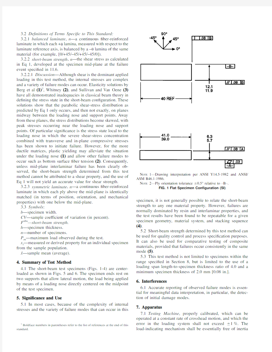
4.1The short-beam test specimens (Figs.1-4)are center-
loaded as shown in Figs.5and 6.The specimen ends rest on
two supports that allow lateral motion,the load being applied
by means of a loading nose directly centered on the midpoint
of the test specimen.
5.Signi?cance and Use
5.1In most cases,because of the complexity of internal
stresses and the variety of failure modes that can occur in this
specimen,it is not generally possible to relate the short-beam strength to any one material property.However,failures are normally dominated by resin and interlaminar properties,and the test results have been found to be repeatable for a given specimen geometry,material system,and stacking sequence (4).5.2Short-beam strength determined by this test method can be used for quality control and process speci?cation purposes.It can also be used for comparative testing of composite materials,provided that failures occur consistently in the same mode (5).5.3This test method is not limited to specimens within the range speci?ed in Section 8,but is limited to the use of a loading span length-to-specimen thickness ratio of 4.0and a minimum specimen thickness of 2.0mm [0.08in.].6.Interferences 6.1Accurate reporting of observed failure modes is essen-tial for meaningful data interpretation,in particular,the detec-tion of initial damage modes.7.Apparatus 7.1Testing Machine ,properly calibrated,which can be operated at a constant rate of crosshead motion,and which the error in the loading system shall not exceed 61%.The load-indicating mechanism shall be essentially free of inertia
7Boldface numbers in parentheses refer to the list of references at the end of this
standard.N OTE 1—Drawing interpretation per ANSI Y14.5-1982and ANSI/ASM B46.1-1986.N OTE 2—Ply orientation tolerance 60.5°relative to –B–.FIG.1Flat Specimen Con?guration
(SI)
lag at the crosshead rate used.Inertia lag may not exceed 1%
of the measured load.The accuracy of the testing machine shall
be veri?ed in accordance with Practices E 4.
7.2Loading Nose and Supports ,as shown in Figs.5and 6,
shall be 6.00-mm (0.250-in.)and 3.00-mm (0.125-in.)diameter
cylinders,respectively,with a hardness of 60to 62HRC,as
speci?ed in Test Methods E 18,and shall have ?nely ground
surfaces free of indentation and burrs with all sharp edges
relieved.
7.3Micrometers —For width and thickness measurements,
the micrometers shall use a 4-to 5-mm (0.16-to 0.2-in.)
nominal diameter ball interface on an irregular surface such as
the bag side of a laminate and a ?at anvil interface on machined
edges or very smooth tooled surfaces.A micrometer or caliper
with ?at anvil faces shall be used to measure the length of the
specimen.The accuracy of the instrument(s)shall be suitable
for reading to within 1%of the sample dimensions.For typical
section geometries,an instrument with an accuracy of 60.002
mm (60.0001in.)is desirable for thickness and width mea-
surement,while an instrument with an accuracy of 60.1mm
(60.004in.)is adequate for length measurement.
7.4Conditioning Chamber ,when conditioning materials at
nonlaboratory environments,a temperature/vapor-level-
controlled environmental conditioning chamber is required that
shall be capable of maintaining the required temperature to
within 63°C (65°F)and the required vapor level to within
63%.Chamber conditions shall be monitored either on an automated continuous basis or on a manual basis at regular intervals.7.5Environmental Test Chamber ,an environmental test chamber is required for test environments other than ambient testing laboratory conditions.This chamber shall be capable of maintaining the test specimen at the required test environment during the mechanical test method.8.Sampling and Test Specimens 8.1Sampling —Test at least ?ve specimens per test condi-tion unless valid results can be gained through the use of fewer specimens,as in the case of a designed experiment.For statistically signi?cant data,consult the procedures outlined in Practice E 122.Report the method of sampling.8.2Geometry :8.2.1Laminate Con?gurations —Both multidirectional and pure unidirectional laminates can be tested,provided that there are at least 10%0°?bers in the span direction of the beam (preferably well distributed through the thickness),and that the laminates are both balanced and symmetric with respect to the span direction of the beam.8.2.2Specimen Con?gurations —Typical con?gurations for the ?at and curved specimens are shown in Figs.1-4.For specimen thicknesses other than those shown,the following geometries are recommended:Specimen length =thickness 36Specimen width,b =thickness 32.0N OTE 2—Analysis reported by Lewis and Adams (6)has shown that a width-to-thickness ratio of greater than 2.0can result in a signi?cant width-wise shear-stress variation.8.2.2.1For curved beam specimens,it is recommended that the arc should not exceed 30°.Also,for these specimens,the specimen length is de?ned as the minimum chord length.8.3Specimen Preparation —Guide D 5687/D 5687M pro-vides recommended specimen preparation practices and should be followed where practical.8.3.1Laminate Fabrication —Laminates may be hand-laid,?lament-wound or tow-placed,and molded by any suitable laminating means,such as press,bag,autoclave,or resin transfer molding.8.3.2Machining Methods —Specimen preparation is impor-tant for these specimens.Take precautions when cutting specimens from the rings or plates to avoid notches,undercuts,rough or uneven surfaces,or delaminations as a result of inappropriate machining methods.Obtain ?nal dimensions by water-lubricated precision sawing,milling,or grinding.The use of diamond tooling has been found to be extremely effective for many material systems.Edges should be ?at and parallel within the speci?ed tolerances.8.3.3Labeling —Label the specimens so that they will be distinct from each other and traceable back to the raw material,in a manner that will both be unaffected by the test method and not in?uence the test method.9.Calibration 9.1The accuracy of all measuring equipment shall have certi?ed calibrations that are current at the time of use of the
equipment.
N OTE 1—Drawing interpretation per ANSI Y14.5-1982and ANSI/
ASME B46.1-1986.
N OTE 2—Ply orientation tolerance 60.5°relative to –B–.
FIG.2Flat Specimen Con?guration (Inch
Pound)
10.Conditioning
10.1Standard Conditioning Procedure —Unless a different
environment is speci?ed as part of the test method,condition
the test specimens in accordance with Procedure C of Test
Method D 5229/D 5229M,and store and test at standard
laboratory atmosphere (2363°C (7365°F)and 50610%
relative humidity).
11.Procedure
11.1Parameters to Be Speci?ed Before Test :
11.1.1The specimen sampling method and coupon geom-
etry.
11.1.2The material properties and data-reporting format
desired.N OTE 3—Determine speci?c material property,accuracy,and data-reporting requirements before test for proper selection of instrumentation and data-recording equipment.Estimate operating stress levels to aid in calibration of equipment and determination of equipment settings.11.1.3The environmental conditioning test parameters.11.1.4If performed,the sampling test method,coupon geometry,and test parameters used to determine density and reinforcement volume.11.2General Instructions :11.2.1Report any deviations from this test method,whether intentional or inadvertent.11.2.2If speci?c gravity,density,reinforcement volume,or void volume are to be reported,then obtain these samples from the same panels as the test samples.Speci?c gravity
and
N OTE 1—Drawing interpretation per ANSI Y14.5-1982and ANSI/ASM B46.1-1986.
N OTE 2—Ply orientation tolerance 60.5°relative to –A–.
FIG.3Curved Specimen Con?guration
(SI)
density may be evaluated by means of Test Methods D 792.
V olume percent of the constituents may be evaluated by one of
the matrix digestion procedures of Test Method D 3171,or for
certain reinforcement materials such as glass and ceramics,by
the matrix burn-off technique of Test Method D 2584.V oid
content may be evaluated from the equations of Test Method
D 2734and are applicable to both Test Methods D 2584and
D 3171.
11.2.3Condition the specimens as required.Store the speci-
mens in the conditioned environment until test time,if the test
environment is different from the conditioning environment.
11.2.4Following ?nal specimen machining and any condi-
tioning,but before testing,measure and record the specimen
width and thickness at the specimen midsection and the
specimen length to the accuracy speci?ed in 7.3.11.3Speed of Testing —Set the speed of testing at a rate of crosshead movement of 1.0mm (0.05in.)/min.11.4Test Environment —If possible,test the specimen under the same ?uid exposure level as that used for conditioning.However,if the test temperature places too severe requirements upon the testing machine environmental chamber,test at a temperature with no ?uid exposure control.In this case,a restriction must be placed upon the time from removal of the specimen from the conditioning chamber until test completion to inhibit nonrepresentative ?uid loss from the specimen.Record any modi?cations to the test environment and specimen weight change after removal from conditioning until test completion.11.4.1Monitor the test temperature by placing an appropri-ate thermocouple at specimen mid-length to be located on
the
N OTE 1—Drawing interpretation per ANSI Y14.5-1982and ANSI/ASME B46.1-1986.
N OTE 2—Ply orientation tolerance 60.5°relative to –A–.
FIG.4Curved Specimen Con?guration (Inch
Pound)
underside of the beam.
11.5Specimen Insertion —Insert the specimen into the test
?xture,with the toolside resting on the reaction supports as
shown in Fig.5or Fig.6.Align and center the specimen such
that its longitudinal axis is perpendicular to the loading nose
and side supports.Adjust the span such that the span-to-
measured thickness ratio is 4.0to an accuracy of 60.3mm
(0.012in.).The loading nose should be located equidistant
between the side supports to within 60.3mm (0.012in.).Both
the loading nose and side supports should overhang the
specimen width by at least 2mm (0.08in.)at each side.In the
case of the ?at laminate test,each specimen end should
overhang the side support centers by at least the specimen
thickness.
11.6Loading —Apply load to the specimen at the speci?ed
rate while recording data.Continue loading until either of the
following occurs:
11.6.1A load drop-off of 30%,
11.6.2Two-piece specimen failure,or
11.6.3The head travel exceeds the specimen nominal thick-
ness.
11.7Data Recording —Record load versus crosshead dis-
placement data throughout the test method.Record the maxi-mum load,?nal load,and the load at any obvious discontinui-ties in the load-displacement data.11.8Failure Mode —Typical failure modes that can be identi?ed visually are shown in Fig.7.However,these may be preceded by less obvious,local damage modes such as transply cracking.Record the mode and location of failure,if possible identifying one or a combination of the modes shown.12.Calculation 12.1Short-Beam Strength —Calculate the short-beam strength using Eq 1as follows:F sbs 50.753P m b 3h (1)where:F sbs =short-beam strength,MPa (psi);P m =maximum load observed during the test,N (lbf);b =measured specimen width,mm (in.),and h =measured specimen thickness,mm (in.).12.2Statistics —For each series of test methods,calculate the average value,standard deviation,and coefficient of varia-tion (in percent)for each property determined as
follows:
FIG.5Horizontal Shear Load Diagram (Curved
Beam)
FIG.6Horizontal Shear Load Diagram (Flat
Laminate)
x 5~(i –1n x i !/n (2)
s n –15?~(i 51n
x i 2–n ~x !2!/~n –1!(3)
CV 51003s n –1/x
(4)where:x ˉ=sample mean (average);s n–1=sample standard deviation;CV =sample coefficient of variation,%;n =number of specimens;and x i =measured or derived property.
13.Report
13.1Report the following information,or references point-
ing to other documentation containing this information,to the
maximum extent applicable (reporting of items beyond the
control of a given testing laboratory,such as might occur with
material details or panel fabrication parameters,shall be the
responsibility of the requester):
N OTE 4—Guides E 1309,E 1434,and E 1471contain data reporting
recommendations for composite materials and composite materials me-
chanical testing.
13.1.1This test method and revision level or date of issue.
13.1.2Whether the coupon con?guration was standard or
variant.
13.1.3The date and location of the test.
13.1.4The name of the test operator.
13.1.5Any variations to this test method,anomalies noticed
during testing,or equipment problems occurring during testing.
13.1.6Identi?cation of the material tested including:mate-
rial speci?cation,material type,material designation,manufac-turer,manufacturer’s batch or lot number,source (if not from manufacturer),date of certi?cation,expiration of certi?cation,?lament diameter,tow or yarn ?lament count and twist,sizing,form or weave,?ber areal weight,matrix type,prepreg matrix content,and prepreg volatiles content.13.1.7Description of the fabrication steps used to prepare the laminate including:fabrication start date,fabrication end date,process speci?cation,cure cycle,consolidation method,and a description of the equipment used.13.1.8Ply orientation and stacking sequence of the lami-nate.13.1.9If requested,report density,volume percent rein-forcement,and void content test methods,specimen sampling method and geometries,test parameters,and test results.13.1.10Average ply thickness of the material.13.1.11Results of any nondestructive evaluation tests.13.1.12Method of preparing the test specimen,including specimen labeling scheme and method,specimen geometry,sampling method,and coupon cutting method.13.1.13Calibration dates and methods for all measurements and test equipment.13.1.14Details of loading nose and side supports including diameters and material used.13.1.15Type of test machine,alignment results,and data acquisition sampling rate and equipment type.13.1.16Dimensions of each test specimen.13.1.17Conditioning parameters and results.13.1.18Relative humidity and temperature of the testing laboratory.13.1.19Environment of the test machine environmental chamber (if used)and soak time at environment.13.1.20Number of specimens tested.13.1.21Speed of
testing.
FIG.7Typical Failure Modes in the Short Beam
Test
13.1.22Maximum load observed during the test,for each
specimen.
13.1.23Load-displacement curves for each specimen.
13.1.24Failure mode of each specimen,identi?ed if pos-
sible from Fig.7.
14.Precision and Bias
14.1Precision —The data required for the development of a
precision statement is not currently available for this test
method.14.2Bias —Bias cannot be determined for this test method as no acceptable reference standard exists.15.Keywords 15.1composite materials;resin and interlaminar properties;short-beam strength
REFERENCES
(1)Berg,C.A.,Tirosh,J.,and Israeli,M.,“Analysis of Short Beam
Bending of Fiber Reinforced Composites,”in Composite Materials:
Testing and Design (Second Conference),ASTM STP 497,ASTM,
1972,pp.206-218.
(2)Whitney,J.M.,and Browning,C.E.,“On Short-Beam Shear Tests for
Composite Materials,”Experimental Mechanics ,V ol 25,1985,pp.
294-300.
(3)Sullivan,J.L.,and Van Oene,H.,“An Elasticity Analysis for the
Generally and Specially Orthotropic Beams Subjected to Concentrated
Loads,”Composites Science and Technology ,V ol 27,1986,pp.
182-191.(4)U.S.Department of Transportation,Federal Aviation Administration,“Test Methods for Composites a Status Report:V olume III Shear Test Methods,”Report No.DOT/FAA/CT-93/17,III,FAA Technical Cen-ter,Atlantic City,1993.(5)Cui,W.,Wisnom,M.R.,and Jones,M.,“Effect of Specimen Size on Interlaminar Shear Strength of Unidirectional Carbon Fibre-Epoxy,”Composites Engineering ,V ol 4,No.3,1994,pp.299-307.(6)Adams,D.F.and Lewis,E.Q.,“Current Status of Composite Material Shear Test Methods,”SAMPE ,V ol 31,No.6,1994,pp.32-41.
The American Society for Testing and Materials takes no position respecting the validity of any patent rights asserted in connection with any item mentioned in this https://www.360docs.net/doc/081226284.html,ers of this standard are expressly advised that determination of the validity of any such patent rights,and the risk of infringement of such rights,are entirely their own responsibility.
This standard is subject to revision at any time by the responsible technical committee and must be reviewed every ?ve years and if not revised,either reapproved or withdrawn.Your comments are invited either for revision of this standard or for additional standards and should be addressed to ASTM Headquarters.Your comments will receive careful consideration at a meeting of the responsible technical committee,which you may attend.If you feel that your comments have not received a fair hearing you should make your views known to the ASTM Committee on Standards,at the address shown below.
This standard is copyrighted by ASTM,100Barr Harbor Drive,PO Box C700,West Conshohocken,PA 19428-2959,United States.Individual reprints (single or multiple copies)of this standard may be obtained by contacting ASTM at the above address or at 610-832-9585(phone),610-832-9555(fax),or service@https://www.360docs.net/doc/081226284.html, (e-mail);or through the ASTM website
(https://www.360docs.net/doc/081226284.html,).
ANSI美国国家标准学会螺纹标准
0.25M0.25x0.0756g0.2500.2350.2010.1870.1600.1406H0.1720.2080.2010.2150.2550.2760.175 M0.25x0.0754g6g0.2500.2350.2010.1930.1600.152 0.3M0.3x0.086g0.3000.2840.2480.2340.2040.1836H0.2170.2540.2480.2620.3060.3270.210 M0.3x0.084g6g0.3000.2840.2480.2390.2040.195 M0.3x0.096g0.3000.2830.2420.2260.1920.1706H0.2060.2470.2420.2570.3060.330 M0.3x0.094g6g0.3000.2830.2420.2330.1920.183 0.35M0.35x0.096g0.3500.3330.2920.2770.2420.2206H0.2560.2970.2920.3070.3560.3800.245 M0.35x0.094g6g0.3500.3330.2920.2830.2420.233 0.4M0.4x0.16g0.4000.3820.3350.3190.2800.2566H0.2960.3400.3350.3510.4070.4320.280 M0.4x0.14g6g0.4000.3820.3350.3250.2800.270 0.45M0.45x0.16g0.4500.4320.3850.3690.3300.3066H0.3460.3900.3850.4010.4570.4820.315 M0.45x0.14g6g0.4500.4320.3850.3750.3300.320 0.5M0.5x0.1256g0.5000.4790.4190.4010.3500.3226H0.3700.4220.4190.4370.5090.5380.350 M0.5x0.1254g6g0.5000.4790.4190.4080.3500.339 0.55M0.55x0.1256g0.5500.5290.4690.4510.4000.3726H0.4200.4720.4690.4870.5590.5880.380 M0.55x0.1254g6g0.5500.5290.4690.4580.4000.389 0.6M0.6x0.156g0.6000.5760.5030.4830.4200.3886H0.4440.5040.5030.5230.6110.6440.420 M0.6x0.154g6g0.6000.5760.5030.4900.4200.407 0.7M0.7x0.1756g0.7000.6730.5860.5640.4900.4546H0.5180.5860.5860.6080.7130.7500.500 M0.7x0.1754g6g0.7000.6730.5860.5720.4900.476 0.8M0.8x0.26g0.8000.7700.6700.6460.5600.5206H0.5920.6680.6700.6940.8140.8560.560 M0.8x0.24g6g0.8000.7700.6700.6550.5600.545 0.9M0.9x0.2256g0.9000.8670.7540.7280.6300.5866H0.6660.7500.7540.7800.9160.9620.630 M0.9x0.2254g6g0.9000.8670.7540.7380.6300.614 1M1x0.256g0.9820.9150.8200.7670.7110.6136H0.7290.8090.8380.909 1.000 1.1070.700 M1x0.254g6g0.9820.9150.8200.7870.7110.633 M1x0.26g0.9830.9270.8530.8050.7660.6826H0.7830.8580.8700.933 1.000 1.0920.700 M1x0.24g6g0.9830.9270.8530.8230.7660.700 1.1M1.1x0.256g 1.082 1.0150.9200.8670.8110.7136H0.8290.9090.938 1.009 1.100 1.2070.800 M1.1x0.254g6g 1.082 1.0150.9200.8880.8110.734 M1.1x0.26g 1.083 1.0270.9530.9050.8660.7826H0.8830.9580.970 1.033 1.100 1.1920.800 M1.1x0.24g6g 1.083 1.0270.9530.9230.8660.800 1.2M1.2x0.256g 1.182 1.115 1.0200.9670.9110.8136H0.929 1.009 1.038 1.109 1.200 1.3070.900 M1.2x0.254g6g 1.182 1.115 1.0200.9870.9110.833 M1.2x0.26g 1.183 1.127 1.053 1.0050.9660.8826H0.983 1.058 1.070 1.133 1.200 1.2920.900 M1.2x0.24g6g 1.183 1.127 1.053 1.0230.9660.900 1.4M1.4x0.36g 1.383 1.308 1.253 1.193 1.166 1.0706H 1.183 1.258 1.270 1.350 1.400 1.509 1.200 M1.4x0.34g6g 1.383 1.308 1.253 1.215 1.166 1.092 M1.4x0.26g 1.383 1.327 1.253 1.205 1.166 1.0826H 1.183 1.258 1.270 1.333 1.400 1.492 1.200 M1.4x0.24g6g 1.383 1.327 1.253 1.223 1.166 1.100 1.6M1.6x0.356g 1.581 1.496 1.354 1.291 1.202 1.0756H 1.221 1.321 1.373 1.458 1.600 1.736 1.250 M1.6x0.354g6g 1.581 1.496 1.354 1.314 1.202 1.098 M1.6x0.26g 1.583 1.527 1.453 1.403 1.366 1.2806H 1.3834936 1.4584936 1.4700962 1.5370962 1.6 1.6958676 1.25 M1.6x0.24g6g 1.583 1.527 1.453 1.421 1.366 1.298 1.7M1.7x0.356g 1.681 1.596 1.454 1.391 1.302 1.1756H 1.321 1.421 1.473 1.558 1.700 1.836 1.300 M1.7x0.354g6g 1.681 1.596 1.454 1.414 1.302 1.198 1.8M1.8x0.356g 1.781 1.696 1.554 1.491 1.402 1.2756H 1.421 1.521 1.573 1.658 1.800 1.936 1.500 M1.8x0.354g6g 1.781 1.696 1.554 1.514 1.402 1.298 M1.8x0.26g 1.783 1.727 1.653 1.603 1.566 1.4806H 1.583 1.658 1.670 1.737 1.800 1.896 1.500 M1.8x0.24g6g 1.783 1.727 1.653 1.621 1.566 1.498 2M2x0.46g 1.981 1.886 1.721 1.654 1.548 1.4086H 1.567 1.679 1.740 1.830 2.000 2.148 1.600 M2x0.44g6g 1.981 1.886 1.721 1.679 1.548 1.433 M2x0.256g 1.982 1.915 1.820 1.764 1.711 1.6106H 1.729 1.809 1.838 1.913 2.000 2.111 1.600 M2x0.254g6g 1.982 1.915 1.820 1.784 1.711 1.630 2.2M2.2x0.456g 2.180 2.080 1.888 1.817 1.693 1.5406H 1.713 1.838 1.908 2.003 2.200 2.360 1.700 M2.2x0.454g6g 2.180 2.080 1.888 1.843 1.693 1.566
北京科技大学金属材料学实验报告思考题
回火的过程实际上就是马氏体分解的过程,也是过饱和固溶的碳从α-Fe中脱溶并形成碳化物的过程。回火温度越高,马氏体分解越充分,分解产物的长大越充分。在回火过程中,回火温度——回火组织——钢的性能之间存在着一一对应关系。回火温度越高,钢的硬度越低。 在150-250之间的回火称为低温回火,回火后的组织称为回火马氏体; 在350-500之间进行的回火称为中温回火,回火后的组织称为回火屈氏体 在500-650之间进行的回火称为高温回火,回火后的组织称为回火索氏体 可以看出,回火之后,α-Fe中固溶的碳明显减少,使得碳固溶强化的作用大大减弱,反映到硬度上,就是随着回火温度升高,一般硬度都会下降。 淬火温度对组织和性能的影响: 根据45钢 “晶粒粗大马氏体,1000摄氏度,水淬,59.1”、 “晶粒细小马氏体,860,水淬,57.1”、 “铁素体+马氏体,770,水淬,46.2”; 40CrNi “晶粒粗大马氏体,1000摄氏度,油淬,40.6”、 “晶粒细小马氏体,860,油淬,50.9”、 T8 “晶粒粗大马氏体,1000摄氏度,水淬,66.2”、 “晶粒细小马氏体,860,水淬,57.3”、 可以得到如下结论: 高温淬火得到粗晶马氏体,低温淬火得到细晶马氏体,而温度在铁素体与奥氏体两相区的淬火得到铁素体+马氏体双相组织。在Ac3线以上,在保温时间相同的情况下,温度越高,得到的马氏体的晶粒越粗大。这是因为淬火温度越高,奥氏体晶粒长大的越快,因此在淬火的时候获得的马氏体晶粒也就越粗大。另外,尽管45钢和T8钢均表现出淬火温度越高,钢的硬度越高,但是本人对这一现象持怀疑态度。所谓金属硬度小,也就是硬度测试仪的压头容易压入金属,即金属容易发生塑性变形。塑性变形本质上是金属中的位错运动导致的。而晶界等会阻挡位错的运动。晶粒越小,同样大小的一块材料中,晶界就越多,对位错运动的阻碍就越大,材料形变的阻力就越大,宏观上就是硬度高。因此我对45钢、T8钢实验数据所显示出来的马氏体晶粒越粗大,硬度越高持怀疑态度。 当淬火温度在两相区的时候,由于出现铁素体,因此硬度会低于细晶马氏体组织。
ASTM D2344_D2344M_美国材料和实验协会标准
3.2De?nitions of Terms Speci?c to This Standard: 3.2.1balanced laminate ,n —a continuous ?ber-reinforced laminate in which each +u lamina,measured with respect to the laminate reference axis,is balanced by a –u lamina of the same material (for example,[0/+45/–45/+45/–45/0]). 3.2.2short-beam strength ,n —the shear stress as calculated in Eq 1,developed at the specimen mid-plane at the failure event speci?ed in 11.6. 3.2.2.1Discussion —Although shear is the dominant applied loading in this test method,the internal stresses are complex and a variety of failure modes can occur.Elasticity solutions by Berg et al (1)7,Whitney (2),and Sullivan and Van Oene (3) have all demonstrated inadequacies in classical beam theory in de?ning the stress state in the short-beam con?guration.These solutions show that the parabolic shear-stress distribution as predicted by Eq 1only occurs,and then not exactly,on planes midway between the loading nose and support points.Away from these planes,the stress distributions become skewed,with peak stresses occurring near the loading nose and support points.Of particular signi?cance is the stress state local to the loading nose in which the severe shear-stress concentration combined with transverse and in-plane compressive stresses has been shown to initiate failure.However,for the more ductile matrices,plastic yielding may alleviate the situation under the loading nose (1)and allow other failure modes to occur such as bottom surface ?ber tension (2).Consequently, unless mid-plane interlaminar failure has been clearly ob- served,the short-beam strength determined from this test method cannot be attributed to a shear property,and the use of Eq 1will not yield an accurate value for shear strength. 3.2.3symmetric laminate ,n —a continuous ?ber-reinforced laminate in which each ply above the mid-plane is identically matched (in terms of position,orientation,and mechanical properties)with one below the mid-plane. 3.3Symbols : b —specimen width. CV —sample coefficient of variation (in percent). F sbs —short-beam strength. h —specimen thickness. n —number of specimens. P m —maximum load observed during the test. x i —measured or derived property for an individual specimen from the sample population. x ˉ—sample mean (average). 4.Summary of Test Method 4.1The short-beam test specimens (Figs.1-4)are center- loaded as shown in Figs.5and 6.The specimen ends rest on two supports that allow lateral motion,the load being applied by means of a loading nose directly centered on the midpoint of the test specimen. 5.Signi?cance and Use 5.1In most cases,because of the complexity of internal stresses and the variety of failure modes that can occur in this specimen,it is not generally possible to relate the short-beam strength to any one material property.However,failures are normally dominated by resin and interlaminar properties,and the test results have been found to be repeatable for a given specimen geometry,material system,and stacking sequence (4).5.2Short-beam strength determined by this test method can be used for quality control and process speci?cation purposes.It can also be used for comparative testing of composite materials,provided that failures occur consistently in the same mode (5).5.3This test method is not limited to specimens within the range speci?ed in Section 8,but is limited to the use of a loading span length-to-specimen thickness ratio of 4.0and a minimum specimen thickness of 2.0mm [0.08in.].6.Interferences 6.1Accurate reporting of observed failure modes is essen-tial for meaningful data interpretation,in particular,the detec-tion of initial damage modes.7.Apparatus 7.1Testing Machine ,properly calibrated,which can be operated at a constant rate of crosshead motion,and which the error in the loading system shall not exceed 61%.The load-indicating mechanism shall be essentially free of inertia 7Boldface numbers in parentheses refer to the list of references at the end of this standard.N OTE 1—Drawing interpretation per ANSI Y14.5-1982and ANSI/ASM B46.1-1986.N OTE 2—Ply orientation tolerance 60.5°relative to –B–.FIG.1Flat Specimen Con?guration (SI)
金属材料拉伸试验标准试样类型及尺寸
金属材料拉伸试验标准试样类型及尺寸 编制: 审核:________________________ 批准:生效日期:
受控标识处: 分发号: 发布日期:2016年9月27日实施日期:2016年9月27日 制/修订记录
1.0 本文件规定了常温下金属材料拉伸试验标准试样的类型,形状及其尺寸测量。 2.0范围 适用于本公司常温下金属材料的拉伸试验所需的比例试样制备。 3.0规范性应用文件 下列文件对于本文件的作用是必不可少的。凡是注日期的应用文件,仅注日期的版本适用于本文件。凡是不注日期的应用文件,其最新版本(包括所有的修改单)适用于本文件。 3.1GB/T 2975钢及钢产品力学性能试验取样位置和试样制备 3.2GB/T 8170数值修约规则与极限数值的表示和判定 3.3GB/T 10623金属材料力学性能试验术语 4.0术语和定义 4.1试件/试样test piece/specimen 通常按照一定形状和尺寸加工制备的用于试样的材料或部分材料。 4.2标距gauge length 用于测量试样尺寸变化部分的长度。 4.3原始标距original gauge length 在施加试验力之前的标距长度。 4.4断后标距final gauge length after fracture 试样断裂后的标距长度。 4.5平行长度parallel length 试样两头部或加持部分(不带头试样)之间平行部分的长度。 4.6断面收缩率percentage reduction of area 断裂后试样横截面积的最大缩减量(S0-S u)与原始横截面积(S0)之比的百分率。 S o-S u Z0=S- S-X100% S0 5.0符号和说明 与试样相关的符号及说明如下:
国内外标准代码一览
国外标准代码一览 国标准: AQ 安全行业标准 BB 包装行业标准 CAS 中国标准化协会标准 CB、CBM 船舶行业标准 CCEC 中国节能产品认证技术要求CECS 工程建设标准化协会标准 CH 测绘行业标准 CJ、CJJ 城镇建设行业标准 CNCA 认证认可委强制认证实施规则CY、CW 新闻出版行业标准 DA 档案行业标准 DB 地震行业标准 DL、DLJ 电力行业标准 DZ 地质矿产行业标准 EJ 核工业行业标准 FZ、FJJ 纺织行业标准 GA 公共安全行业标准 GB 国家标准 GBJ 工程建设国家标准 GBn 国家部标准
GH 供销合作行业标准 GHZB 国家环境质量标准 GJB 国家军用标准 GWKB 国家污染物控制标准 GY、GYJ 广播电影电视标准 HAF 核安全法规 HB、HBMm 航空行业标准 HBC 环境产品技术要求 HCRJ 中国环境保护产品认定技术条件HG 化工行业标准 HGJ 化工行业工程建设规程 HJ 环境保护行业标准 HJB 海军标准 HJBZ 环境标志行业标准 HS 海关行业标准 HY 海洋行业标准 、JBJ 机械行业标准 JC 建材行业标准 JG 建筑行业标准 JGJ 建筑行业工程建设规程 JJ 城乡建设环境保护行标 JJF 国家计量检定规
JJG 国家计量检定规程 JR 金融行业标准 JT、JTJ、JTG 交通行业标准JY 教育行业标准 LB 旅游行业标准 LD 劳动和劳动安全行业标准LS 粮食行业标准 LY 林业行业标准 MH 民用航空行业标准 MT 煤炭行业标准 MZ 民政行业标准 NY 农业行业标准 QB、QBJ 轻工行业标准QC 汽车行业标准 QJ 航天行业标准 QX 气象行业标准 SB、SBJ 商业行业标准 SC 水产行业标准 SD、SDJ 水利电力行业标准SH、SHJ 石油化工行业标准SJ 电子行业标准 SL、SLJ 水利行业标准
金属材料工程专业方向
金属材料工程专业方向 一、专业简介及培养目标 金属材料工程是国家经济建设的支柱,在航空航天、能源化工、国防军工、冶金机电等各行业均发挥着至关重要的作用,也是西安交通大学优势学科之一,在国内外享有较高的知名度。金属材料工程主要研究金属材料性能优化的基本理论,探索提高材料使用性能的有效途径,了解金属材料的性能特点及其工程应用。学生通过院级课程的学习已经具备了材料科学与工程方面的基础理论和一定的实验技能,本专业重点向学生介绍金属材料合金理论、常见工程构件的失效分析、材料内部缺陷的检测技术、金属功能材料、复合材料等相关知识,使学生掌握金属材料合金化基础理论知识,熟悉几种重要的金属材料及其力学性能与应用。培养学生选择材料和使用材料的科学思路。使学生能从事工程零构件的失效分析工作,提出预防零件失效的具体措施,使学生掌握金属材料内部缺陷无损检测技术,提出预防零件失效的具体的措施,了解复合材料、生物材料及功能材料的基本理论及要求,培养学生完整的金属材料知识体系。本专业的培养目标是使学生具备现代化建设所要求的系统材料知识、基础理论知识及工程技术知识,具有新材料、新产品、新工艺研究开发能力。金属材料工程专业具有学士、硕士、博士授予权,设有博士后流动站,是"211工程"建设学科的二级学科。金属材料工程专业的科学研究紧密结合国家科技发展的重大需求,瞄准国际前沿,开拓研究思路,不断提高研究水平,保持本学科在国内外的特点和优势。 二、课程设置 根据培养目标,金属材料工程专业方向的课程设置主要以金属材料为核心,课程体系包括合金与强化理论、材料选择与应用、零件失效分析、组织缺陷检测等主要内容。主要课程有:金属材料及热处理,失效分析与防止,金属功能材料,复合材料,材料无损检测技术,生物材料。 表1 金属材料工程专业课程
美国材料实验协会
标识:G 85 - 98 美国材料实验协会 100Barr Harbor Dr. West Conshohocken, PA 19428 摘自ASTM年度合定本,版权所有ASTM 改良后盐雾实验的标准操作规程1 本标准以固定标识G85发放;紧跟在标识后的数字表明初次采用的年代,或最新一次变更年代。在圆括号内的数字表明了最新一次的批准年代。上标(ε)表示从上一次批准至今编辑上的变动。 本标准已通过美国国防部的批准。 1.范围 1.1本操作规程因盐雾实验工程规范的需要先后进行了 五次修改。以下是它们以时间为顺序的发展历程。 1.1.1 附件A1 醋酸连续盐雾实验 1.1.2附件A2酸化盐雾循环实验 1.1.3附件A3 海水酸化循环实验 1.1.4附件A4 二氧化硫盐雾循环实验 1.1.5附件A5电解液稀释干燥/喷雾循环实验 1.2本标准不是描述实验修改的类型,实验样本或某一特定产品暴露在盐雾环境中的时间,更不是对某一实验结果进行解释。 1.3本标准并不意味着提出某一产品所有的安全特性,如果某一产品有安全特性要求,还要联系它的用途来分析。使用本标准的人有责任商议并建立合适和对人体无害的操作规程,并在使用前确定有关参数合适的调节限度。 2.参考文献 2.1ASTM标准: B117 盐雾实验操作规范2 D609 测试油漆、清漆、转化膜、和表面涂层产品的冷扎钢板预备操作3 D1141 海水替代品工程标准4 D1193 反应水工程标准5 D1654 用于评价油漆或涂层样件在腐蚀环境下状况的实验方法3 E 70 测定电极水溶液PH值实验方法6 3.意义与价值 本操作规范适用黑色金属和有色金属;同时也适用与有机物和无机物涂层。当出现与B117中描述不同或更恶劣的 1.本操作规程为ASTM G-1金属的腐蚀委员会管辖,并直接隶属与G01.05腐蚀实验室测试分会管辖。 现行版本在1998年10月批准。1998年11月出版发行。最早发行版本为G85-85,前一版本为G85-94。 2.ASTM标准年度合定本,第3卷,第2章。 3. ASTM标准年度合定本,第6卷,第1章。 4.ASTM标准年度合定本,第11卷,第2章。 5. ASTM标准年度合定本,第11卷,第1章。 6. ASTM标准年度合定本,第15卷,第5章。环境时,在此描述的变异是非常有用的。 4.仪器 4.1实验柜 4.1.1盐雾实验的仪器包括盐雾室,酸性溶液贮藏池,合适的压缩气体供给系统,一个或多个雾化喷嘴,试件安放装置,盐雾室加热装置,和必要的控制设备。实验柜的尺寸和具体的构造是多样的,可自行确定,但提供的实验条件满足本操作规范的要求。实验柜建造的材料应对腐蚀盐雾不产生影响。合适的实验仪器应可以满足B117附录A1中描述的实验条件以及在每一个附加条目中所必须的改动。 4.1.2设计实验柜时应使得积聚在实验柜天花板或盖子上的溶液不会掉落在试件上。不要将从试件上掉落的溶液回收到溶液贮藏池。 4.1.3给实验柜装配一个或多个定时装置,以便实现间断喷雾或周期性输入气体,或同时实现两者。 4.2气体供给 4.2.1确保压缩空气可以供给到喷嘴或雾化酸性溶液的喷嘴没有油污并且压缩空气的供给压力在69到172kpa之间,约合10到25磅/每平方英尺。 注解 1 -空气的供给系统可以采取让空气通过一个湿式气体洗涤器或通过长度至少为610mm(约合2英尺)的清洁物质如石棉、羊毛或者活性氧化铝(俗称矾土)。 4.2.2饱和塔(泡罩塔)内的温度由不同的实验方法来决定。 4.3盐雾室内的环境 4.3.1温度–盐雾暴露区的温度因实验方法的不同而有所不同。对于各种不同的实验方法,推荐的盐雾暴露区的温度请参考附件。记录实验柜闭合后盐雾暴露区的温度每天至少2次,每次至少间隔7小时(除了周末和节假日时,盐雾实验不因为试件的暴露,重新排列、移除或对酸性溶
金属材料-拉伸试验-标准试样类型及尺寸
金属材料-拉伸试验-标准试样类型及尺寸
金属材料拉伸试验标准试样类型及尺寸
编制: 审核: 批准: 生效日期: 受控标识处: 分发号: 发布日期:2016年9月27日实施日期:2016年9月27日 制/修订记录
1.0 目的 本文件规定了常温下金属材料拉伸试验标准试样的类型,形状及其尺寸测量。 2.0 范围 适用于本公司常温下金属材料的拉伸试验所需的比例试样制备。 3.0 规范性应用文件
下列文件对于本文件的作用是必不可少的。凡是注日期的应用文件,仅注日期的版本适用于本文件。凡是不注日期的应用文件,其最新版本(包括所有的修改单)适用于本文件。 3.1 GB/T 2975 钢及钢产品 力学性能试验取样位置和试样制备 3.2 GB/T 8170 数值修约规则与极限数值的表示和判定 3.3 GB/T 10623 金属材料 力学性能试验术语 4.0 术语和定义 4.1 试件/试样test piece/specimen 通常按照一定形状和尺寸加工制备的用于试样的材料或部分材料。 4.2 标距gauge length 用于测量试样尺寸变化部分的长度。 4.3 原始标距original gauge length 在施加试验力之前的标距长度。 4.4 断后标距final gauge length after fracture 试样断裂后的标距长度。 4.5 平行长度parallel length 试样两头部或加持部分(不带头试样)之间平行部分的长度。 4.6 断面收缩率percentage reduction of area 断裂后试样横截面积的最大缩减量(S 0-S u )与原始横截面积(S 0)之比的百分率。 U S -S =100%Z X S 5.0 符号和说明 与试样相关的符号及说明如下:
常见标准代一览表
常见标准代号一览表 中国标准: CB- 中国船舶行业标准 CH- 中国测绘行业标准 CJ- 中国城镇建设行业标准 CY- 中国新闻出版行业标准 DA- 中国档案工作行业标准 DB- 中国农机工业标准 DJ- 中国电力工业标准 DL- 中国电力建设行业标准 DZ- 中国地质矿产行业标准 EJ- 中国核工业行业标准 FZ- 中国纺织行业标准 GB- 中国国家强制性标准 GB/T-中国推荐性国家标准 GJB-中国国家军用标准 GY- 中国广播电影电视行业标准 GA- 中国公共安全行业标准 HB- 中国航空工业行业标准 HG- 中国化工行业标准 HJ- 中国环境保护行业标准 HY- 中国海洋工作行业标准 JB-中国机械行业(含机械、电工、仪器仪表等)强制性行业标准 JC- 中国建筑材料行业标准 JB/T-中国机械行业(含机械、电工、仪器仪表等)推荐性行业标准 JG- 中国建筑工业行业标准 JR- 中国金融系统行业标准 JT- 中国公路、水路运输行业标准 JY- 中国教育行业标准 JZ- 中国建筑工程标准 LD- 中国劳动和劳动安全行业标准 LY- 中国林业行业标准 MH- 中国民用航空行业标准 MT- 中国煤炭行业标准 MZ- 中国民政工作行业标准 NY- 中国农业行业标准 QB- 中国轻工行业标准 QC- 中国汽车行业标准 QJ- 中国航天工业行业标准 SB- 中国商业行业标准 SC- 中国水产行业标准 SH- 中国石油化工行业标准 SJ- 中国电子行业标准 SL- 中国水利行业标准
SN- 中国进出口商品检验行业标准 SY- 中国石油天然气行业标准 TB- 中国铁路运输行业标准 TD- 中国土地管理行业标准 TY- 中国体育行业标准 WB- 中国卫生标准 WH- 中国文化行业标准 WJ- 中国兵器工业标准 XB- 中国稀土行业标准 YB- 中国黑色冶金行业标准 YC- 中国烟草行业标准 YD- 中国邮电通信行业标准 YS- 中国有色金属行业标准 YY- 中国医药行业标准 ZB- 中国专业标准 ZBY-中国仪器行业专用标准 ZY- 中国中医行业标准 CNS-台湾工业标准 国际标准: ISO-国际标准化组织标准 JSO/R-国际标准化组织建议 IIW-国际焊接协会标准 JCAO-国际民用航空组织标准 ICRP-国际射线防护委员会标准 美国标准: ASTM STD- 美国材料与试验协会标准 AASHTO STD-美国国家公路及运输公务员协会标准 ANSI STD- 美国标准协会标准 AIAG STD -自动化工业行动集团标准 API STD- 美国石油协会标准 ASNT(SNT) STD -美国无损检测协会 AREA STD- 美国铁路工程协会标准 ASME STD- 美国机械工程师协会标准 AIA STD- 美国航空学会标准 AWS STD- 美国焊接协会标准 FAA STD- 美国联邦标准 MIL-STD - 美国军用标准 MSS STD- 美国制造商标准化协会标准 ASA-美国国家标准 NCRP STD - 美国国家辐射防护与测量理事会标准 SAE-美国汽车工程师协会标准 NAS-美国国家航空航天标准 AMS-美国宇航材料规范
金属材料工程综合性设计性实验报告
金属热处理综合性、设计性实验报告课题名称:45号钢正常淬火与回火专业:金属材料工程 班级: 3班 姓名:訾春雨 学号:0907024308 指导教师:马臣
实验地点:佳木斯大学金属材料教研室 实验课题名称:45号钢的淬火与回火 实验课题目的:对比在不同温度下对45号钢进行淬火,回火实验。后的组织及其硬度HRC之间的影响 实验组成员: 组长:陈伟强 组员:訾春雨 霍长亮 孙国威 刘继宗 王晓旭 杨建
一、实验目的 通过选材,测试原材料硬度,设计热处理工艺,进行热处理(淬火,回火),测试处理后材料硬度,制备金相组织,在显微镜下进行观察。研究组织构成,分析材料成分、性能、热处理工艺组织结构之间的关系。培养综合分析能力。 二.实验设备 砂轮机,火花图谱,热处理中温炉5台,高温炉1台,金相磨抛光机4台,金相显微镜3台,布氏硬度计1台,洛氏硬度计3台,盐水1桶,机油1桶。金属材料试件(5种) 三.实验步骤 1.材料选择: 拟制造零件:拖拉机传动轴、活塞销、收割机刀片、锉刀、滚动轴承等。 根据零件挑选试样,后用砂轮机磨试样,观看活化形貌,对照火花图谱,鉴别材料。 材料牌号判定结果:45号钢 2.试样力学性能测定: 3.设计热处理工艺: 根据材料牌号,计划用于制造活塞销零件。采用回火工艺,零件硬度要求达到50-65HRC 查表制定热处理工艺。 淬火温度:800℃ 保温时间:t=KD K=1.0min/mm D为零件直径t=1×30=30分钟 淬火介质:水 回火温度:400℃ 回火时间:240分钟 画出热处理工艺
4.热处理试验: 将淬火炉 炉温升到800℃ 回火炉 炉温升到400℃、放入工件,保温60分后,进行淬火和回火。 5.热处理后材料硬度测试: 用HR150洛氏硬度计测量淬火,回火后试样硬度。 测试淬火后硬度值:56.4HRC 回火后硬度值:31.2HRC- 6.制备金相试样: 通过磨平、粗磨、抛光、腐蚀与吹干等制样步骤,制备金相试样。(写明过程) 1.取样 用金相切割机或线切割机床截取,切割时要用水冷却,以免试样受热引起组织变化纵向取样,大小通常一般为φ12×15mm 圆柱体 2.磨光 目的是得到一个平整光滑的表面。磨光分粗磨和细磨。 粗磨:一般材料可用砂轮机将试样磨面磨平;要倒角倒边。 细磨:目的是消除粗磨留下的划痕,为下一步的抛光作准备,细磨又分为手工细磨和机械细磨。 手工细磨:选用不同粒度的金相砂纸(180、240、400、600、800),由粗到细进行磨制。磨时将砂纸放在玻璃板上,手持试样单方向向前推磨,切不可来回磨制,用力均匀,不宜过重。每换一号砂纸时,试样磨面需转90°,与旧划痕垂直,以此类推,直到旧划痕消失为止。试样细磨结束后,用水将试样冲洗干净待抛。 3.抛光 目的是去除试样磨面上经细磨留下的细微划痕,使试样磨面成为光亮无痕的镜面。此次使用的是机械抛光。 机械抛光在金相抛光机上进行。抛光时,试样磨面应均匀的轻压在抛光盘上。并将试样由中心至边缘移动。并做轻微移动。在抛光过程中要以量少次数多和由中心向外扩展的原则不断加入抛光微粉乳液,抛光应保持适当的湿度,因为太湿降低磨削力,使试样中的硬质相呈现浮雕。湿度太小,由于摩擦生热会使试样生温,使试样产生晦暗现象,其合适的抛光湿度是以提起试样后磨面上的水膜在3~5秒钟内蒸发完为准。 抛光压力不宜
ASTM F150-98 美国材料与试验协会标准导电及静电耗散型弹性地板电阻的测试方法
ASTM F150-98 美国材料与试验协会标准 导电及静电耗散型弹性地板电阻的测试方法 1、适用范围 1.1 本测试方法适用于医院、计算机机房、洁净室、通道、军需品仓库或其它需防止人体 产生静电的场所的卷材或片材弹性地板的导电性(绝缘性)的测试。 1.2 本标准无意于标定所有与使用相关的安全关系,而是为标准的使用者建立适合的安全 可靠的实践应用与决策时提供优先考虑的规范。 2、参考标准 2.1ASTM标准 D 2240橡胶性能的测试方法――硬度测试 E177 ASTM测试方法在实际应用中的误差 E691实验性研究导电性测试方法的精确度 2.2 其它标准 EOS/ESD――SD7.1 地面材料――材料的电阻性能 NFPA99-1990 设备的维护 联邦测试方法NO.501a,测试方法8311――电传导 Mono#11医院手术室的导/防静电地板 3、术语 3.1定义 3.1.1导电地板――依照8.1.1或8.2.1测试所得的平均电阻值在大于2.5×10⁴Ω,小于1.0×10⁶Ω范围内的卷材与片材弹性地板。若依照8.2.2测试要求平均电阻不小于2.5×10⁴Ω,个别电阻值不小于1.0×10⁴Ω的地板。
3.1.2静电耗散型地板――依照8.1.1或8.2.1测试所得的平均电阻值大于1.0×10⁶Ω且小于1.0×10⁹Ω的卷材或片材弹性地板。依照8.2.2测试,要求平均电阻值不小于1.0×10⁶Ω且不大于1.0×10⁹Ω。 4、意义及应用 4.1导电及静电耗散型地板(防静电地板)是通过与人体或物体的电气连接而防止人体或 物体静电积聚的一种简便方式。防静电地板对其电阻值是有规定的。地板表面提供了一条人体及设备与地面连通的适当导电路径,以防止静电荷积聚的危害。为使防静电地板发挥有效作用,防静电地板上的工作人员应穿防静电鞋。 4.2有些地面材料的电阻会随时间变化。这类地板材料应该要求初始电阻足够低或足够 高,以使其随时间增加或减少后的电阻值仍不超出前面所述的产品阻值的限制范围(见联邦测试方法NO.501a 测试方法8311)。 5、试验装置 5.1自动量程电阻表(例如兆欧表)或者其它外形适宜的电流表,要求其测量误差不大于 10%,为安全起见,所使用的电源应有电流限制,通常低于5.0mA,这种仪器的测试电压为500±10V或100±10V直流电压,或者两种电压都有。测试导线应与地面绝缘。 5.2电极――A型与B型电极都可使用,但是一对电极必须是同一型号的。 5.2.1 A型电极――带有与欧姆表连接端子的两个圆柱型金属电极,每个电极重 2.27Kg±28g,并且底面是直径为6 3.5±1.58mm的干燥,平整的接触圆面。 5.2.2 B型电极――两个重2.27Kg±28g圆柱型金属电极,其直径为63.5±1.58mm,每个电极贴有邵氏硬度为50~70的导电物质(见D2240)。当测试电压为10V或测试金属性表面时要求电极底导电贴垫电阻小于1KΩ。 5.3A型电极的制备:在平坦、光滑、坚硬的表面放一张厚0.0127~0.0254mm的铝或锡 的薄片,然后在薄片上放一个直径为64mm的橡胶垫,厚度为6.4mm,硬度在50~70(见标准D2440),再把电极放在橡胶垫上,用橡皮圈或强力胶固定锡箔。 6、试验样品
ANSI AMERICAN NATIONAL STANDARD INSTITUTE 美国国家标准委员会.
ANSI AMERICAN NATIONAL STANDARD INSTITUTE美国国家标准委员会 API AMERICAN PETROLEUM INSTITUTE美国石油学会 ASME AMERICAN SOCIETY OF MECHANICAL ENGINEERS美国机械工程师协会 ASTM AMERICAN SOCIETY OF TESTING AND MATERIAL+美国材料实验协会 BB:BOLTED BONNET栓联压盖 BG:BOLTED GLAND栓联添料压盖BC:BOLTED COVER栓联阀盖 BE:BEVELED END坡口端 BW:BUTT WELD对焊 CA:CORROSION ALLOWANCE腐蚀余量 CL:CLASS压力等级CON:CONCENTRIC同心的 CS:CARBON STEEL碳钢 DN:NOMINAL DIAMETER公称直径 D:DISC阀板(盘) D&S:DISC AND SEAT阀板(盘)和阀座ECC:ECCENTRIC偏心的 EFW:ELECTRIC FUSION WELD电熔焊(接) F-PORT:FULL-PORT全通径(用于阀门) F:FILLER填料(用于缠绕式垫片) FIRE-S:FIRE SAFE防火安全(密封)结构FLG:FLANGE法兰 GR:GRADE分类(牌号)
HB:BRINNEL HARDNESS NUMBER布氏硬度 ID:INTERNAL DIAMETER内径 IN OR”:INCH英寸 L:LARGE大端(母管)LR:LONG RADIUS大半径 MM:MILIMETER毫米 MIN:MINIMUM最小 MOD:MODIFIED改良的(修正的) MS:METAL SEAL金属密封 NPT:NATIONAL TAPER PIPE THREAD(美国)国家标准锥管螺纹 OS&Y:OUTSIDE SCREW&YORK轭架式外螺纹OD:OUTSIDE DIAMETER外径 PE:PLAIN END平端 PS(B):PRESSURE SEAL BONNET压力密封阀盖(帽) P(S)C:PRESSURE SEAL COVER压力密封阀盖RF:RAISED FACE凸台面 RJ:RING JOINT环连接 S:SMALL小端(支管)SCH:SCHEDULE壁厚等级 SG:SCREW GLAND螺纹压盖SMLS:SEAMLESS无缝的 SO:SLIP ON平焊 SS:STAINLESS STEEL不锈钢 STD:STANARD OR STANDARD WEIGHT标准壁厚(重量)STL:STELLITE司太立硬质合金SW:SOCKET WELD承插焊