EPSON10000使用手册
EPSON 投影机 说明书

目錄安全使用須知•安全使用須知 (2)•使用和保管上的注意事項 (10)支援與維修指南•本公司提供的實用軟體 (14)•故障檢查表 (15)•Epson投影機聯繫清單 (17)安全使用須知操作投影機時,請先閱讀所有安全和操作使用須知。
閱讀所有使用須知後,請保存本注意事項以備將來參考。
本文件和投影機均使用圖像符號來顯示安全使用投影機的方法。
請了解並遵守注意事項的符號,避免造成人身傷害和財產損失。
符號說明本符號代表若有疏忽,可能因錯誤操作而造成人身傷害或甚至死亡的注意事項。
本符號代表若有疏忽,可能因錯誤操作而造成人身傷害或外傷的注意事項。
代表不能執行的動作的符號不要執行不要拆解不要觸摸不要弄濕不要在潮濕地區使用不要放置在不穩的表面上代表應該執行的動作的符號使用須知從插座上拔下插頭⨸r發生以下情況時,請將投影機插頭從插座上拔下,並將所有維修工作交由專業維修人員執行:•如果有煙霧、異味或奇怪的噪音從投影機中發出。
•如果液體或異物掉入投影機內部。
•如果投影機掉落或機殼損壞。
在以上情況繼續使用,可能會引起火災或觸電。
不要試圖自行維修投影機。
請把全部維修作業交由合格的維修人員執行。
請將投影機放在方便拔掉插頭的插座附近使用。
除非使用說明書中有特別說明,否則不要打開投影機上方的任一個蓋子。
不要試圖拆解或改裝投影機(包括消耗品)。
請把全部維修作業交由合格的維修人員執行。
投影機內的電壓會造成嚴重的人身傷害。
如果要將投影機安裝在天花板上,應由合格的技師採用認可的吊裝裝備進行安裝。
如果不正確執行安裝工作,投影機可能會掉落。
這樣可能會造成人身傷害或意外。
請向您的經銷商聯絡以便執行安裝工作。
如果您在吊裝座上使用膠粘劑以防螺釘鬆動,或在投影機上使用潤滑劑、油類製品等,可能會造成機殼破裂,使投影機從吊裝座上掉落。
這樣可能會對吊架座下方的人造成嚴重的傷害,並可能損壞投影機。
安裝或調整吊裝座時,請勿使用膠粘劑防止螺釘鬆動,也不要使用潤滑劑、油類製品等。
Epson产品用户手册说明书

Read these instructions before using your product.Important Safety Instructions: When using telephone equipment, youshould always follow basic safety precautions to reduce the risk of fire, electric shock, and personal injury, including the following:• D o not use this Epson ® product near water.• A lways keep this guide handy.• A void using a telephone during an electrical storm. There may be a remote risk of electric shock from lightning.• D o not use a telephone to report a gas leak in the vicinity of the leak.Caution: To reduce the risk of fire, use only a No. 26 AWG or largertelecommunication line cord.1 Remove all protective materials from the product.2 L ift up the scanner unit and remove all protective materialsfrom inside the product, then close the scanner unit.6 Close the ink pack tray cover and lock it.7 P ress OK on the LCD screen to start charging the ink.Ink charging takes approximately 5 minutes. A messageappears when ink charging is complete.4 Load paperFor instructions on loading envelopes or legal-size paper, or using the rear paper feed slot, see the online User’s Guide .1 M ake sure the product is done charging the ink, then pullout the paper cassette.2 S lide the side edge guides all the way out and set thefront edge guide to the paper size you are using.3 I nsert paper with the glossy or printable side down.Standard paper: Thick paper:Note: Make sure the paper is under the arrow mark for your paper type and loaded against the front edge of the cassette.4 S lide the edge guides against the paper, but not tootightly.2 P ress an ink pack tray to release it, then pull the tray out.3 S hake an ink pack 10 times, then remove it from thepackaging.Note: Do not touch the green chip on the ink pack.4 M ove the handle forward, place the ink pack into the inkpack tray until it clicks, then move the handle back to itsoriginal position .Note: Make sure the ink pack is fullyinserted and level with the top of the ink pack tray.5 I nsert the ink pack tray into the printer. Repeat steps 2 to5 for the other ink packs.Note: The ink packs are keyed to fit into the correct color slot.If you cannot insert the ink pack tray all the way, do not force it. Make sure the ink pack color matches the color slot on the printer.3 F ollow the instructions on the computer screen to run thesetup program.4 W hen you see the Select Your Connection screen, selectone of the following and follow the on-screen instructions:• Wireless connectionIn most cases, the software installer automatically attempts to set up your wireless connection. If setup is unsuccessful, you may need to enter your network name (SSID) and password.• Direct USB connectionMake sure you have a USB cable (not included).• Wired network connectionMake sure you have an Ethernet cable (not included).PCL or PostScript driver (WF-C5790)Download the software and see your online User’s Guide for instructions..jm/support/wfc5790Mobile printingConnect wirelessly from your smartphone, tablet, or computer.Print documents and photos from across the room or around the world:• Print directly from your iOS device. Simply connect your printer and device to the same network and tap the action icon to select the print option.• Use Epson Print Enabler (free from Google Play™) with Android™ devices (v4.4 or later). Then connect your printer and device to the same network and tap the menu icon to select the print option.• Print remotely with Epson Connect™ and Google Cloud Print™. See your online User’s Guide for instructions or learn more at .jm/connect .Any problems?Network setup was unsuccessful.• Make sure you select the right network name (SSID).• Restart your router (turn it off and then on), then try toconnect to it again.• The printer can only connect to a network that supports 2.4 GHz connections. If your router offers both 2.4 GHz and 5 GHz connections, make sure 2.4 GHz is enabled.• If you see a firewall alert message, click Unblock or Allow to let setup continue.• If your network has security enabled, make sure you enter your network password (WEP key or WPA passphrase) correctly. Be sure to enter your password in the correct case.56 S elect the paper settings on the product’s control panel.12 I f prompted, press Proceed on the LCD screen to set upthe fax, or press Close to set it up later.Note: If your computer does not have a CD/DVD drive or you are using a Mac, an Internet connection is required to obtain the product software.To print from a Chromebook™, go to.jm/support/gcp for instructions.Standard software package1M ake sure the product is NOT CONNECTED to your computer.Windows ®: If you see a Found New Hardware screen, click Cancel and disconnect the USB cable.2 I nsert the product CD or download and run your product’ssoftware package. For the latest software, visit:WF-C5710.jm/support/wfc5710WF-C5790.jm/support/wfc5790。
Epson 打印机用户手册说明书
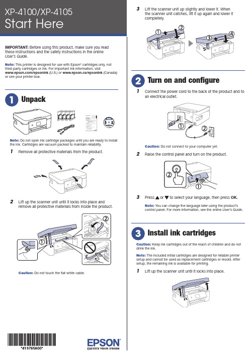
Do not open ink cartridge packages until you are ready to installthe ink. Cartridges are vacuum packed to maintain reliability.emove all protective materials from the product.3 L ift the scanner unit up slightly and lower it. Whenthe scanner unit catches, lift it up again and lower itcompletely.1 C onnect the power cord to the back of the product and toan electrical outlet.Caution: Do not connect to your computer yet.2 R aise the control panel and turn on the product.3 OK.Note: You can change the language later using the product’scontrol panel. For more information, see the online User’s Guide.Caution: Keep ink cartridges out of the reach of children and do notdrink the ink.Note: The included initial cartridges are designed for reliable printersetup and cannot be used as replacement cartridges or resold. Aftersetup, the remaining ink is available for printing.1 L ift up the scanner unit until it locks into place.9 F ollow the on-screen instructions to adjust the printquality of your product.Note:• Y ou need to load paper before you can adjust the print quality.See “Load paper” below for details.• S elect Adjust Later if you want to adjust the print quality later. For more information, see the online User’s Guide.See the online User’s Guide for information about loading capacity, available paper types and sizes, and loading envelopes.1 M ake sure the product is not charging. Then flip thefeeder guard forward, raise the paper support, and tilt itbackwards slightly.2 3 L4 S tightly.5 P6 F ollow the instructions on the LCD screen to select yourpaper settings.• Print from wherever you are, next to your printer or remotely, with Epson Connect™ and Google Cloud Print™. Learn more at /connect (U.S.) or www.epson.ca/connect (Canada).• Use voice-activated assistants to print a variety of creative and everyday items from your Epson product. Simply add your product to an Epson Connect account, then link the account to a voice-activated assistant. See /voice (U.S.) orwww.epson.ca/voice (Canada) for more information.* M ay require the Epson Print Enabler or Mopria Print Service app from Google Play™.Any problems?Network setup was unsuccessful.• M ake sure you select the right network name (SSID).• Restart your router (turn it off and then on), then try toconnect to it again.• T he printer can only connect to a network that supports 2.4 GHz connections. If your router offers both 2.4 GHz and 5 GHz connections, make sure the 2.4 GHz connection is enabled.• I f you see a firewall alert message, click Unblock or Allow to let setup continue.• I f your network has security enabled, make sure you enter your network password (WEP key or WPA passphrase) correctly. Be sure to enter your password in the correct case.AB1# for There are lines or incorrect colors in my printouts.Run a nozzle check to see if there are any gaps in the printout. Then clean the print head, if necessary. See the online User’s Guide for more information.The product’s screen is dark.Make sure your product is turned on, and press any button to wake it from sleep mode.Setup is unable to find my printer after connecting it with a USB cable.Make sure the printer is turned on and that it is securelyconnected as shown:Note:• I f you are using a Mac or your computer does not have a CD/DVD drive, an Internet connection is required to obtain the product software.• T o print from a Chromebook™, go to /support/gcp (U.S.) orwww.epson.ca/support/gcp (Canada) for instructions.Firmware Update Notice: Epson periodically provides firmware updates to address issues of security, performance, minor bug fixes and ensure your printer functions as designed. Your printer was designed to work only with genuine Epson ink cartridges, therefore some updates may affect the functionality of third-party ink.1 M ake sure the product is NOT CONNECTED to yourcomputer.W indows ®: If you see a Found New Hardware screen, click Cancel and disconnect the USB cable.2 I nsert the product CD (Windows only) or download andrun your product’s software package. For the latestsoftware, visit:XP-4100/support/xp4100 (U.S.) www.epson.ca/support/xp4100 (Canada)XP-4105/support/xp4105 (U.S.) www.epson.ca/support/xp4105 (Canada)3 F ollow the instructions on the computer screen to run thesetup program.4 W hen you see the Select Your Connection screen, selectone of the following and follow the on-screen instructions:• Wireless connectionIn most cases, the software installer automatically attempts to set up your wireless connection. If setup is unsuccessful, you may need to enter your network name (SSID) and password.• Direct USB connectionM ake sure you have a USB cable (not included).Mobile and voice-activated printing• Print directly from your iOS device. Simply connect your printer and device to the same network and tap the action icon to select the print option.• Print directly from your Android™ (v4.4 or later) devices*. Simply connect your printer and device to the same networkand tap the menu icon to select the print option.XP-4100/XP-4105 replacement ink cartridges。
Epson 打印机用户指南.pdf_1701920843.434027说明书

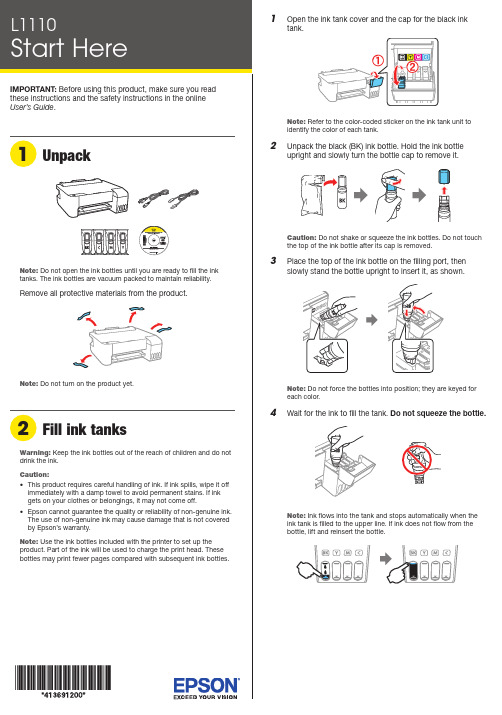
Do not open the ink bottle until you are ready to fill the ink tank. The ink bottle is vacuum packed to maintain reliability.Note: Ink charging takes about 10 minutes. When the powerlight stops flashing, ink charging is complete.C aution: Do not turn off the product, open the printer cover, orload paper while the product is charging or you’ll waste ink.See the online User’s Guide for information about loading capacity, available paper types and sizes, loading envelopes, and using the rear feed slot.1 M ake sure the product is done charging the ink. Open thepaper cassette cover and pull out the paper cassette until2 Slide the edge guides all the way out.3Note: Make sure the paper is loaded against the front of thecassette.Note:• I f you are using a Mac or your computer does not have a CD/DVD drive, an Internet connection is required to obtain theproduct software.• T o print from a Chromebook™, go to/support/gcp (U.S.) orwww.epson.ca/support/gcp (Canada) for instructions.1 M ake sure the product is NOT CONNECTED to yourcomputer.Windows®: If you see a Found New Hardware screen, clickCancel and disconnect the USB cable.2 I nsert the product CD (Windows only) or download andrun your product’s software package. For the latestsoftware, visit /support/etm1170 (U.S.) or www.epson.ca/support/etm1170 (Canada).3 F ollow the instructions on the computer screen to run thesetup program.4 W hen you see the Select Your Connection screen, selectone of the following:• Wireless connectionIn most cases, the software installer automaticallyattempts to set up your wireless connection. If setupis unsuccessful, you may need to enter your networkname (SSID) and password.• Direct USB connectionMake sure you have a USB cable (not included) ready.• Wired network connectionMake sure you have an Ethernet cable (not included).。
Epson 打印机用户手册.pdf_1701927021.181767说明书
Flashing
On
Initial ink charging may not be complete. Be sure to complete the steps in the “Fill ink tanks” and “Turn on and charge the ink” sections.
Paper is out or multiple pages have fed into the paper support. Load paper correctly in the paper support, then press the button.
Setup is unable to find my product after connecting it with a USB cable. Make sure your product is on and securely connected as shown:
5 Pull out the output tray, then raise the paper stoห้องสมุดไป่ตู้per.
4 Slide the edge guides against the paper, but not too
tightly.
Any problems?
There are lines or incorrect colors in my printouts. Run a nozzle check to see if there are any clogged nozzles. Then clean the print head, if necessary. See the online User’s Guide for more information.
Xrite-DTP70和Epson XL 10000XL扫描仪的使用说明说明书

How to use Xrite and Epson ScannerByungseok MinMehul JainElectronic Imaging Systems LaboratorySchool of Electrical EngineeringPurdue UniversityTable of ContentPg. No.Overview 3Chapter 1: Managing X-rite1.1 Software Location 51.2 Designing Test Patterns 5 - 10 1.3 Modifying Test Patterns 11 - 13 1.4 Measuring Test Patterns 14 – 15 1.5 Exercise examples 16 - 18Chapter 2: Managing Scanner2.1 Scanner Details 192.2 Screenshots 20 - 25 2.3 Scanning Procedure 26 - 28OverviewScanner calibration is the process to estimate CIE XYZ values of the printed image from the device dependent RGB values of the scanned image.Spectro-photometer and scanner are used to obtain CIE XYZ value and to scan the image. It is essential to know how to use the devices to obtain correct data.This manual consists as follows.First, it will describe how to use Xrite-DTP70 to measure CIE XYZ values of hardcopy. And then it will describe how to use Epson XL 10000XL scanner with the option we have to choose.The other parts consist of gray balancing and regression model to explain the analytical scanner calibration model.CHAPTER 1 Managing X-rite1.1 Software LocationThe software used to manage X-rite is ‘Colorport 1.0.1’ and can be found in‘C:\Program Files\X-Rite\ColorPort\ColorPort’1.2 Designing Test Patterns in Colorport:Though the X-rite comes with a variety of test patterns, it might be best to design a different one for application in research work. Following steps should be followed while designing a test pattern.unch X-rite by running ‘C:\Program Files\X-rite\ColorPort\ColorPort’2.Select X-Rite DTP 70 from the ‘Measurement Device’ menu. Select CMYKin the color space and select the appropriate paper size and format.Figure 1 shows a screenshot of the application with the above mentionedsettings selected.Figure 1 : Screenshot showing initial settings.3. Select ‘New’ from the Patch Set menu. A window opens up as shown in Figure2.Figure 2 : Screenshot showing window that opens up after New is selected.4. Press ‘+’ sign repeatedly to get desired number of patches. A CMYK value can be given to each of the patches individually, this is optional. If left blank, a value of zero is assumed automatically. Give a name with which the pattern should be saved. Click on ‘Save’ once done with adding patches. Figure 3 shows a screen shot of ‘Customize’ window with 100 patches.5. Once ‘Save’ is pressed, the customization window disappears and the original window shows a preview of how the test pattern looks like. As mentioned earlier, the color of patches is irrelevant and only helps in depicting the visualization of test pattern. To make the designed test pattern match the requirements a few specifications can be customized.6. Click on ‘Properties’ button placed below ‘Measurement Device’. A window opens up as shown in Figure 4. ‘Patch Width’ and ‘Patch Height’ can be altered from 6 mm to 20 mm. These values can be changed to accommodate more or less test patches in a row. The header and trailer length can be altered toincrease/decrease the distance between the test patches and top and bottom red line. Figure 3 : Screenshot showing customization window7. Selecting ‘OK’ closes the properties window and updates the preview window with the change in settings.8. Click on ‘Margins’ in next to the ‘Paper Size’ section in the main window tochange the page margins. This will again give the freedom to increase / decrease the number of test patches in one row. Also, either of ‘Portrait’ and ‘Landscape’ formats can be selected to meet the requirements for the test patch.9. Test patches can be added/ deleted/modified anytime by clicking on ‘Customize’ under the ‘Patch Set’ column.Figure 4 : Screenshot showing Properties window10. Once satisfied with the test pattern, click on ‘Save Target’ and save it as a tiff file in a preferred location.11. There are further possibilities of fine tuning the test pattern. See the next section for more details.Figure 5 shows a test pattern designed using Colorport software.Figure 5: Test Pattern designed using ColorportIt should be noted that the black patches in the first and the last column represent a grid which X-rite uses to approximate the start and the end point. The test pattern above has 12 rows and 28 columns that makes the total number of test patches to be 336.When a test pattern is created using Colorport, several files are generated. One is ‘.tif’ file which is an image representation of the test pattern designed. A ‘.xml’ file is generated which contains all the information about the designed test pattern and can be used for importing and exporting test patterns. ‘.tab’ file is also generated and it contains information about the individual test patches in a test pattern. This file can be used to modify the total number of test patches etc.1.3 Modifying Existing Test Patterns:If a test pattern already exists, it can be modified in two different ways depending on the format of the file of the test pattern.1.3.1 .xml fileIf the test pattern exists in form of a .xml file, then changes can be made to the xml file to meet the requirements. The .xml file contains detailed information about specifications of the test patterns that would be used by X-rite formeasurement purposes. Figure 6 shows a sample .xml file for one of the testpatterns created using Colorport.Figure 6: screenshot showing sample .xml fileAs is clear from Figure 6 above, the .xml file contains information such as patch width, height, page width and height, page margins, etc. These values can be changed individually to meet the requirements. Unfortunately, there is no method of viewing the effects of changes made to .xml file. So, a trial and error method needs to be adopted to make the .xml file work for the test patterns in hand. Once the changes have been made, the file should be saved againas .xml file and imported into Colorport. Steps to Import the file are listed below.Importing/Exporting .xml fileFrom the file menu in Colorport, select ‘Target Manager’. A window opens up as shown in Figure 7. Click on ‘import’ and then give the location of .xml file. Same procedure can be followed for exporting a .xml file.Figure 7: screenshot showing ‘Target Manager’ window1.3.2 .tab file.tab file can be used to import individual test patches within a test pattern to create a new test pattern. To import test patches from a .tab file, follow the following steps:1. Open the .tab file in notepad and save it in .txt format.2. Make sure that the correct color space ( RGB / CMYK etc.) is selected in the menu under ‘Color Space’ column.3. Select ‘New’ from the menu in ‘Patch Set’ column.4. Click on ‘Import Patches’ button in the window that opens up. Figure 8 shows the results of importing test patches.Figure 8: screenshot showing import of test patches from .tab file5. Once the patches have been imported, relevant steps mentioned in section 1.2 can be followed to modify the test pattern as needed.1.4 Measuring Test PatternsOnce the test pattern has been created / modified using any of the steps mentioned in the previous sections, it is ready to be measured with X-rite.1. Click on the ‘Measure Target’ tab in the main window of Colorport software.2. Select X-Rite DTP 70 from the drop down menu under ‘Measurement Device’ and click on connect.3. Select the target that is to be measured in the ‘Target’ column. If the name is not listed in the menu then follow the steps mentioned for importing .xml file in section 1.3.1. Figure 9 shows a screenshot showing the ‘Measure Target’ window with appropriate settings.Figure 9: screenshot showing the measure target window.4. The right half of the window shows preview of the patches to be measured. ‘Measurement Status’ column in the lower left section of the window displays the progress of the current measurement cycle.5. Insert the printout of test pattern in X-rite and hit the orange button on the left side of X-rite. The X-rite then takes measurements6. Once the X-rite has taken measurements, click on the ‘Save Data’ button andchoose the settings in the window that comes up as shown in Figure 10 below.7. Click on ‘Continue’ button and provide a location and name to save the data file.The data file can be opened up in notepad. The data file has three columns and each row corresponds to a patch in the test pattern. For example, if there are 100 patches in the pattern, there will be 100 rows. First row in the date file corresponds to XYZ values of first patch in the first row of test pattern. Second row corresponds to second patch in the first row of the test pattern and so on. Figure 10: screenshot showing the Save Data window.1.5 Exercise examples1.5.1 Q60 measurementKodak Q60 is most common patch to be used for scanner calibration. Figure 11 shows a sample Q60 patch.Figure 11: Sample Q60 patchIn particular, the gray-levels in the bottom part of the Q60 patch are used for gray balancing. Following steps describe the procedure to be carried out for measuring all the color in Q60.1. Measure the width and height of the small square size and the gray boundaries very carefully. Any small error in measurement will bring out critical failure to obtain correct CIE XYZ values of Q60, since the aperture will measure wrong place.2. Based on the measured values, divide the whole patch including boundaries into the set of small squares. The boundary may have the same width as the small square. After all, you should be able to design .tab profile for Q60 and TIFF file that can print out the set of those squares.3. Develop a test profile in Colorport to measure Q60 by Xrite DTP70. The first step will be to develop a profile by Colorport with 18 row and 26 columns of test patches (You will see why it is 18x26). Be sure the width, height, margin and so on.4. After making the profile, the Colorport will produce a TIFF file. Print out the TIFF file, and locate the Q60 on the printed image so that you measure Q60 as if it were the printed image.5. Take the measurements using X-rite and the design developed in Step 3.1.5.2 Cyan patch for scanner calibration1. Determine the size of the patch you want to create.2. Determine the number of small squares with its height and width so that the sum of the length of the square is same as the patch size.3. Develop a profile in Colorport to measure those squares, then you willhave .tab file and tif file.4. Generated tif file will have black reference marks in both left and right side of the patch. Since you are not able to have a color of the patch, you have to refill the color by creating the same tif image by MATLAB or C.By writing your own code, you will have the tif file with the same size, but can fill the color as you want. Please be sure that your new tif file has the black reference marks too. The sample tif file is shown in figure 12.5. Print out the new tif file, and measure by Xrite.Figure 12: Sample tif fileCHAPTER 2 Managing Scanner2.1 Scanner detailsThe scanner being calibrated is Epson Expression 10000XL. The software used for scanning is VueScan (version : 8.1.28).2.2 ScreenshotsThis section presents screenshots of the settings to be used while calibrating the scanner. It is imperative that the same settings be used for measurement purposes. The choices in settings have been explained wherever necessary.2.2.1 Input TabThe settings shown in Figure 11 below are for use with Auto Document Feeder. It is important to set the bits per pixel to 24 bit RGB and Scan resolution to 600 dpi.Figure 13: screenshot of Vuescan’s ‘Input’ Tab2.2.2 Crop TabFigure 14: screenshot of Vuescan’s ‘Crop’ TabIt should be noted that most of the values will be different depending on the test pattern being scanned. For more info please see section number 2.3.1The values in ‘Border %’ , ‘Buffer %’, ‘X images’, ‘Y images’ and ‘Lock aspect ratio’ should be used as it is for the scanner settings.2.2.3Filter TabFigure 15: screenshot of Vuescan’s ‘Filter’ TabUnder the filter tab, set all the values as shown above. The values are chosen in such manner so as to minimize the software’s modifications in the actual measurements.Figure 16: screenshot of Vuescan’s ‘Color’ TabAll of the values shown in Figure 16 above should be carefully used as it is, while configuring the software.There are a variety of options present under ‘Color balance’ menu such as manual, neutral, tungsten etc. It was found out that ‘None’ works the best for calibration and measurement purposes.Selecting the correct color spaces is crucial too, and an incorrect choice might significantly alter the RGB measurements.Figure 17: screenshot of Vuescan’s ‘Output’ TabThe output files should be saved in ‘.tif’ format with ‘compression off’ and the tiff file type should be 24 bit RGB.2.2.6 Preferences TabAll the values shown in Figure 18 can be changed as per convenience and need. Figure 18: screenshot of Vuescan’s ‘Preferences’ Tab2.3 Scanning ProcedureOnce the values discussed in section 2.2 have been entered into Vuescan, it needs to be configured for scanning a particular area of the test pattern. The procedure is discussed in the next section.2.3.1 Previewing the scan area:1. Slide the paper into the auto document feeder(ADF) of the scanner.2. Click on the ‘Crop’ tab in the Vuescan software window and make sure‘Preview area’ has been set to maximum.3. An extra sheet of paper must be put below the test pattern being previewed. Skipping this step would result in an error.4. Click on ‘Preview’ button on bottom left of the screen. The ADF then feeds the test pattern and the extra sheet of paper in to the scanner. Figure 19 on the next page displays a snapshot of the preview screen.5. Select the crop area by adjusting the dotted lines. The image can be rotated by clicking on the input tab and then making changes in the ‘rotation’ menu.6. Once satisfied with the crop area and other settings, go to File menu and save the settings by selecting ‘Save options’. The settings file is saved as a ‘.ini’ file.7. After saving the file, close the Vuescan software, remove the last sheet of paper from the scanner and re-open the Vuescan software.The test patterns are now ready to be scanned. Figure 19: screenshot of Vuescan’s Preview window2.3.2 Scanning the Test Patterns1. Slide the stack of papers into the auto document feeder(ADF) of the scanner.2. Insert an extra sheet of paper in the end. This step is important, if not followed it would result in last test pattern not being scanned.3. In the Vuescan software, go to file menu and select ‘load options’. Load the ‘.ini’ file that was saved while setting the crop area ( see section 2.3.1).4. Set the appropriate output file name by going to output tab in the software window. Inserting a ‘number+’ symbol with the name starts the file name from that number and increments the number each time by 1. For example, specifying the file name as ‘magenta1+.tif’ would save the first file as ‘magenta1.tif’ the second file as ‘magenta2.tif’ and so on.5. After the scanner has finished scanning, the files can be accessed and are ready to be used.CHAPTER 3 Gray Balancing3.1 IntroductionGray balancing is a process by which a power curve relationship is developed between measured luminance (Y) and RGB values for a monochrome test pattern. The Power curve is used to convert RGB values to linearized RGB values.3.2 Procedure3.2.1 Data AcquisitionFor gray balancing purposes, it is recommended that a Q60 patch be used. It is an industrial standard and is used in wide variety of applications. Figure 18 shows a sample Q60 patch.Figure 18: Sample Q60 patchThe gray-levels in the bottom part of the Q60 patch should be used for gray balancing.Following steps describe the procedure to be carried out for gray balancing.1. Develop a test pattern in Colorport which will measure the gray patches in the Q60 test pattern. Since, Q60 is a lot different from standard test patterns measured by X-rite, a quick solution might be to develop a test pattern in Colorport with 1 row and 25 columns of test patches. The patch width, height and page margins should be carefully adjusted to match the requirements. This pattern then can be used as a guiding outline for measuring the gray patches in Q60. For more information on how to design a test pattern in Colorport, please refer to section 1.2.2. Take the measurements using X-rite and the design developed in Step 1.3. Scan the Q60 patch using Epson 10000XL scanner. Crop the scanned image to retain only the gray test patches. Figure 19 shows an image of the scanned Q60 patch.Figure 19: Scanned Q60 patch3.2.2 CalculationNow that the data has been acquired, a power curve relationship needs to be developed between the measured luminance and measured RGB values.1. Scale the measured RGB data by dividing it with 255 so that the data ranges from 0 to 1.2. Scale the measured Y values by a factor of (255/100).3. Use the inbuilt Matlab tool ‘cftool’ to fit a power curve. Figure 20 shows a snapshot of cftool.Figure 20: cftool window in Matlab.4. Click on ‘Data’ button and assign the scaled R values to x axis and scaled Y values to y axis.5. Click on the ‘Fitting’ button and in the window that opens up, choose ‘Power’ for the type of fit and choose ‘a*x^b +c’ in the section right below the type of fit column. Figure 21 shows a snapshot of settings to be chosen.Figure 21: Fitting window in cftool ( Matlab)6. Click on Apply to fit the curve. The Results section shows the equation of the fitted power curve and the associated rmsE value. This value should be as low as possible.7. Repeat steps 4,5 and 6 for green and blue components of the measured data and find the power curve equations that are the best fit for the data.This concludes the process of gray balancing . The equations developed in this section will be used in the next step called ‘ Matrix Transformation’.Figure 22 shows a plot of the gray balancing curves developed for a test case.Figure 21: Gray balancing curvesCHAPTER 4 Matrix Transformations4.1 IntroductionMatrix Transformation is a method of finding a 3 X 3 matrix for each of the color channels (Cyan, Magenta and Yellow). Data is first converted to linearized RGB using the gray balancing technique described in Chapter 3. Matrix is thencalculated by using functions in Matlab to divide the LRGB values by measured XYZ values.4.2 Procedure1. Generate a set of test patterns consisting of patterns for different gray levels for a single color channel. The set should contain sufficient number of patterns varying from lightest to darkest gray level for that color channel. This can be done using Matlab or C. Figure 22 shows test patterns that were used forcalibrating Epson 10000 XL2. Create the pattern in Colorport that will measure the generated test patterns.3. Measure the test patterns using X-rite and save all the data files. Figure 22: Test Pattern generated for matrix transformation4. Scan all the test patterns and extract the RGB values using Matlab or equivalent.5. For the measured RGB values, use the power curves calculated during Gray Balancing ( see chapter 3) to calculate the corresponding linearized RGB values.6. Once the LRGB values have been calculated, use ‘\’ ( left matrix divide operator) to divide the LRGB values with the measured XYZ values.7. The operation in Step 6 results in a 3 x 3 matrix which is the transformation matrix for that color channel.8. Now that the matrix has been calculated, it is important to check the validity of results.9. For this, generate a separate set of test patterns for that color channel and scan them to find out the RGB values.10. Convert the measured RGB values to LRGB values and use the 3x3 matrix calculated in step 7 to estimate the XYZ values.11. Find out the error between the estimated and actual XYZ values by first converting these values to LAB format and then calculating the deltaE.12. The deltaE value should be as small as possible. Typically it should be less than 0.513. Repeat steps 1 – 12 for the remaining two color channels.The 3x3 matrices have now been calculated and this concludes the process of scanner calibration.。
Epson 投影仪用户指南说明书
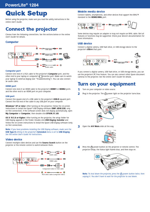
Quick SetupBefore using the projector, make sure you read the safety instructions in the online User’s Guide .Connect the projectorChoose from the following connections. See the sections below or the online User’s Guide for details.ComputerComputer portComputer port, and the an audio cable.HDMI portConnect one end of an HDMI cable to the projector’s HDMI1 or HDMI2 ports and the other end to an HDMI port on your computer.USB portConnect the square end of a USB cable to the projector’s USB-B (square) port. Connect the flat end of the cable to any USB port on your computer.Windows ® XP or later: After turning on the projector, follow the on-screen instructions to install the Epson ® USB Display software (EMP_UDSE.EXE ; only on first connection). If the software screen does not display automatically, open My Computer or Computer , then double-click EPSON_PJ_UD .OS X 10.5.8 or higher: After turning on the projector, the setup folder for USB Display appears in the Finder. Double-click USB Display Installer andfollow the on-screen instructions to install the Epson USB Display software (only on first connection).Note: If you have problems installing the USB Display software, make sure the USB Type B setting in the projector’s Extended menu is set to USB Display . See the online User’s Guide for instructions.Video deviceConnect multiple video devices and use the Source Search button on theprojector or the remote control to switch between them.RCA video cable (composite video)Mobile media deviceConnect tablets, smartphones, and other devices that support the MHL™ standard to the HDMI2/MHLport.Some devices may require an adapter or may not require an MHL cable. Not all features or functions may be supported. Check your device’s documentation for more information.USB deviceConnect a digital camera, USB flash drive, or USB storage device to the projector’s USB-A(flat) port.If you connect a digital camera, USB flash drive, or USB storage device, you can use the projector’s PC Free feature. You can also connect other Epson document cameras to the projector. See the online User’s Guide for details.Turn on your equipment1 Turn on your computer or video source.2Plug in the projector. Thepower light on the projector turns blue.3O4 PNote: To shut down the projector, press the power button twice, thenunplug it. You don’t have to wait for the projector to cool down.12845 U se the arrow buttons on the remote control to highlight any of theoptions on the Home screen that appears, then press to select it. Youcan display a QR code, switch between projection sources, and quicklyaccess various adjustment options from this screen.6 T he default language of the menu system is English. To select anotherlanguage, press the Menu button on the projector or remote control.Select Extended and press . Select Language and press . Selectyour language and press . Press the Menu button to exit the menusystem.Adjust the image1 I f you don’t see an image, press the Source Search button on theprojector or the remote control to select the image source.Note: If you still see a blank screen or have other display problems, see2 T3 To reduce or enlarge the image, turn the zoom ring.4 Turn the focus ring to sharpen the image.5 I f your image looks like or, you may have placed the projectoroff to one side of the screen at an angle. Place the projector directly infront of the center of the screen, facing the screen squarely. If you can’tmove the projector, use the horizontal keystone slider on the projector tocorrect the image shape.,Using the remote controlMake sure the batteries are installed as shown (two AA batteries).Choose which sourceto displayTurn projectoron and offAccess projectormenusTurn off projectordisplayAccess the HomescreenNavigate projectormenusFor more information on using the remote control, see the onlineUser’s Guide.Project wirelesslyFollow the steps here to connect the projector over a wireless network.If you’re projecting from a computer, it must have a wireless card or built-in wireless interface, and be running Windows 10, Windows 8, Windows 7,Windows Vista®, Windows XP Professional x64, or Windows XP, or OS X 10.5.8to 10.10.x.1 P ress the Menu button on the remote control, select the Networkmenu, and press .2 Choose Network Configurationand press .3 Select the Wireless LAN menu and press .4 C hoose Connection Mode, press , select Quick for a directconnection to a computer, tablet, or smartphone, then press again.When you’re finished, press Esc to return to the Wireless LAN menu.Note: For instructions on setting up an Advanced connection for aconnection to a router or access point, see the online User’s Guide.5 T o prevent the SSID and IP address from appearing on the networkstandby screen, set the SSID Display and IP Address Display settings to Off.6 W hen you’re finished selecting settings in the Wireless LAN menu, pressEsc.7 S elect Complete and press , then select Yes and press again tosave your settings.Install network softwareInstall links to download the network software and manuals from the projector CD. Downloads require an Internet connection. You can also install the software and manuals from the Epson website, as described in “Where to get help.”To project over the network, install the EasyMP® Network Projection software on each computer you will project from. To monitor and control your projector over the network, install the EasyMP Monitor software (Windows only). To project from multiple PCs over the network, install the EasyMP Multi PC Projection software.Click the icons on your desktop to download and install the software and their manuals. See the manuals for instructions on installing and using the software.Project wirelessly from a mobile deviceYou can connect your mobile device and projector using Epson iProjection™ and a QR code. Make sure the latest version of Epson iProjection is installed on your device.Install the Epson iProjection appTo project from an iOS or Android™ device,download and install the Epson iProjection app.Visit /projectorapp (U.S.) orepson.ca/projectorapp (Canada) for more information.Direct wireless connectionMake sure your device and Epson projector are not connected to a network and your Epson projector’s Connection Mode is set to Quick.1Tap iProjection on your device’s Home screen.2 Tap Projectorto open the Search Projector menu.3 Tap Read QR code.4 P oint your device’s camera at the QR code your projector displays; theQR code is read automatically.5 Tap OK to register your projector’s Wi-Fi profile.6 Tap Install to install your projector’s Wi-Fi profile.7 Tap Install Now at the Unsigned Profile notification.8 Tap Done to exit the Profile Installed screen.9 Tap OK to confirm the connection to the projector.10 N ote the projector network name (SSID) shown on your device’s screen.Then go to the Wi-Fi settings on your device to select that network.Your device and Epson projector are now work connectionMake sure your projector and mobile device are connected to the same network.1Tap iProjection on your device’s Home screen.2 Tap Projectorto open the Search Projector menu.3 Tap Read QR code.4 P oint your device’s camera at the QR code your projector displays; theQR code is read automatically.Your device and Epson projector are now connected. TroubleshootingIf you see a blank screen or the No signal message after turning on your computer or video device, check the following:•M ake sure the Status light on the projector is blue and not flashing, and the A/V Mute slide is open.•P ress the Source Search button on the projector or the remote control to switch to the correct image source, if necessary.•P ress the Home button on the projector or remote control to verify the source input and settings.•I f you’re using a Windows laptop, press the function key on your keyboard that lets you display on an external monitor. It may be labeled CRT/LCD or have an icon such as . You may have to hold down the Fn key while pressing it (such as Fn + F7). Wait a moment for the display to appear.•I f you’re using a Mac laptop, open System Preferences and select Displays. Click the Arrangement tab and select the Mirror Displayscheckbox.Where to get helpManualsFor more information about using the projector, click the icons on your desktop to access the online manuals (requires an Internet connection). If you don’t see icons to the manuals, you can install them from the projector CD or go to the Epson website, as described below.Telephone support servicesTo use the Epson® PrivateLine® Support service, call (800) 637-7661. This service is available for the duration of your warranty period. You may also speak with a support specialist by calling (562) 276-4394 (U.S.) or (905) 709-3839 (Canada). Support hours are 6 AM to 8 PM, Pacific Time, Monday through Friday, and7 AM to 4 PM, Pacific Time, Saturday. Days and hours of support are subject to change without notice. Toll or long distance charges may apply.Internet supportVisit /support (U.S.) or epson.ca/support (Canada) for solutions to common problems. You can download utilities and documentation, get FAQs and troubleshooting advice, or e-mail Epson.For more information on wireless projection, visit/wirelessprojectors.RegistrationRegister today to get product updates and exclusive offers. You can use the CD included with your projector or register online at /webreg.Optional accessoriesFor a list of optional accessories, see the online User’s Guide.You can purchase screens or other accessories from an Epson authorized reseller.To find the nearest reseller, call 800-GO-EPSON (800-463-7766). Or you canpurchase online at (U.S. sales) or epson.ca (Canadian sales).Wireless noticeContains wireless LAN 802.11b/g/n moduleModel: WN7122BEPThis document provides safety instructions and describes the specifications. Read thisdocument carefully before use to ensure your safety and product performance.The grantee is not responsible for any changes or modifications not expressly approvedby the party responsible for compliance. Such modifications could void the user’sauthority to operate the equipment. This equipment should be installed and operatedkeeping the radiator at least 7.9 inches (20 cm) or more away from person’s body. Thisdevice is restricted to indoor operations only.EPSON, PowerLite, and EasyMP are registered trademarks, Epson iProjection is a trademark, and EPSON ExceedYour Vision is a registered logomark of Seiko Epson Corporation. PrivateLine is a registered trademark andEpson Connection is a service mark of Epson America, Inc.Mac and OS X are trademarks of Apple Inc., registered in the U.S. and other countries.Android is a trademark of Google Inc.General Notice: Other product names used herein are for identification purposes only and may be trademarksof their respective owners. Epson disclaims any and all rights in those marks.This information is subject to change without notice.© 2015 Epson America, Inc., 9/15Printed in XXXXXX CPD-42655R1。
EPSON指导教程(2024)

2024/1/30
1
目 录
2024/1/30
• EPSON品牌及产品概述 • EPSON打印机使用指南 • EPSON扫描仪操作教程 • EPSON投影仪使用教程 • EPSON数码相机操作指南 • EPSON墨水及耗材选购指南
2
01 EPSON品牌及产 品概述
2024/1/30
回放功能
支持SD卡和内置存储,可将照 片和视频保存到相机内存或外部 存储卡中。
31
拍摄技巧与后期处理建议
01
02
03
04
光线选择
选择合适的光线条件进行拍摄 ,避免过强或过弱的光线影响
照片质量。
2024/1/30
对焦技巧
使用相机自动对焦功能,确保 拍摄主体清晰锐利;在需要时 ,可使用手动对焦进行调整。
03
扫描参数设置
包括彩色扫描、黑白扫描、灰度 扫描、文字识别(OCR)等功能 ,可根据需求选择。
根据文档类型和扫描需求,合理 设置扫描参数,如分辨率、亮度 、对比度等。
2024/1/30
19
扫描仪故障排除与解决方案
常见故障及原因
包括设备无法识别、扫描图像不清晰、扫描速度慢等 问题,分析可能的原因。
投影仪安装与调试步骤
2024/1/30
01
调整投影仪的亮度和对比度,以 获得清晰的投影效果。
02
如果需要,可以使用投影仪的梯 形校正功能,调整投影画面的形 状。
25
投影操作及功能展示
01
投影操作
02
打开投影仪,选择输入信号源。
2024/1/30
03
使用遥控器或投影仪面板上的按键进行操作。
26
- 1、下载文档前请自行甄别文档内容的完整性,平台不提供额外的编辑、内容补充、找答案等附加服务。
- 2、"仅部分预览"的文档,不可在线预览部分如存在完整性等问题,可反馈申请退款(可完整预览的文档不适用该条件!)。
- 3、如文档侵犯您的权益,请联系客服反馈,我们会尽快为您处理(人工客服工作时间:9:00-18:30)。
Epson10000系列喷墨打印机使用手册浙江恒晟图文制作有限公司2005-3-23基本设置进行打印机驱动程序设置 取消打印进行打印机驱动程序设置要进行基本设置以打印您的文档,请访问打印机驱动程序中的主菜单和打印纸菜单。
在打印纸菜单中,您可以在卷纸上为打印、自动旋转、自动裁切和打印页面线进行特殊设置。
有关打印机软件的详细信息,请按下驱动程序设置窗口中的帮助按钮以参见用户帮助。
主菜单单击文件菜单上的打印。
将出现打印对话框。
确保选择您的打印机然后单击属性或选件。
您可能需要单击这些按钮的组合。
将出现驱动程序设置窗口。
单击主窗口菜单以显示主菜单。
从介质类型列表中选择打印机中装入的介质。
打印纸菜单注意:介质类型设置决定了其他的可用设置,所以您始终应该首先进行这个设置。
在墨水框中,如果您使用UltraChrome墨水,则选择彩色/黑白照片以打印彩色,或选择黑色以打印草图或仅黑色文本。
如果您使用ColorFast墨水,则选择彩色以用彩色打印,或选择黑色以用黑白打印。
确保选择模式框中的自动单选按钮。
注意:当选择自动时,打印机驱动程序将控制所有基于当前介质类型设置和墨水设置的详细设置。
如果出现滑动块,则调整模式框中的速度和质量。
根据哪个更重要将滑动块向左或向右拖动。
这个设置通常根据您的介质类型设置而自动确定。
注意:根据选择的介质类型不同,滑动块可能出现在模式窗口中。
单击打印纸图标以显示打印纸菜单。
版面菜单从纸张来源列表中选择打印机中装入的打印纸类型。
从打印纸尺寸列表中选择打印机中装入的打印纸尺寸。
注意:大部分Windows应用程序具有覆盖打印机驱动程序中设置的打印纸尺寸设置的功能。
当使用卷纸时,设置所需的卷纸选项。
请参见卷纸选项。
进行方向、份数和可打印区域设置。
单击版面图标以显示版面菜单。
选择缩小/放大并且如果需要的话调整打印图像的尺寸。
注意:当从纸张来源列表中选择卷纸(横幅)时,这个功能不可用。
打印时,将出现显示打印过程和打印机状态的EPSON进程表。
进程表取消打印要取消进程中的打印,请按下EPSON进程表上的停止按钮。
您也可以暂停或重新开始打印。
要暂停打印,请按下暂停按钮。
要继续打印,请再次按下这个按钮。
单击窗口底部的确定按钮。
屏幕将返回到应用程序的打印设置对话框(或类似的对话框)。
单击打印以打印文档。
告诫:当您停止进程中的打印时,为了获得较佳效果,您需要再次从开始处开始打印。
否则打印图像中可能会出现不对齐或条纹。
检查打印机和打印作业状态使用进程表使用EPSON假脱机管理器(仅适用于Windows Me,98和95) 使用EPSON Status Monitor 3使用进程表当您向打印机发送打印作业时,将打开如下图所示的进程表。
当打印机和计算机之间建立双向通信时,进程表指示当前打印作业的进程并提供打印机状态信息。
这个进程表也显示了有关更好打印和出错消息的有用提示,说明如下所示。
EPSON打印提示获得大部分EPSON打印机驱动程序之外的提示出现在进程表窗口底部。
每30秒钟出现一条新提示。
有关显示提示的详细信息,请单击详细按钮。
注意:当速度和进程对话框中的显示进程表设置关闭时,将不会出现进程表。
有关详细信息,请参见使用速度和进程。
使用EPSON假脱机管理器(仅适用于Windows Me,98和95)EPSON假脱机管理器类似于Windows打印管理器。
如果EPSON假脱机管理器一次接收到两个或多个打印作业,按接收的顺序将它们排成一列(或打印队列)。
当打印作业到达列的顶部时,EPSON假脱机管理器将打印作业发送到打印机中。
当它在任务栏上出现之后,单击PSON Stylus Pro 10600 UC (对于UltraChrome墨水的用户)、EPSON Stylus Pro 10600 CF (对于ColorFast墨水的用户)或EPSON Stylus Pro 10600 DYE (对于Dye墨水的用户)按钮。
您可以看到队列中打印作业的状态和信息。
您也可以使用假脱机管理器取消、暂停和继续或重新开始选择的打印作业。
使用EPSON Status Monitor 3EPSON Status Monitor3显示了打印机状态的详细信息。
访问EPSON Status Monitor 3这是访问EPSON Status Monitor 3的两种方法。
双击Windows任务栏上的打印机形状快捷图标。
要将快捷图标添加到任务栏上,请参见进行监视参数设置。
打开打印机驱动程序,单击应用工具菜单,然后单击EPSON Status Monitor3。
当您访问EPSON Status Monitor 3时,将出现下列窗口。
注意:在使用EPSON Status Monitor3之前,确保阅读自述文件。
要打开这个文件,单击开始,指向程序或所有程序和EPSON 或EPSON打印机,然后单击EPSON Stylus Pro 10600 UC Readme (对于UltraChrome墨水用户)、EPSON Stylus Pro 10600 CF Readme (对于ColorFast墨水用户)或EPSON Stylus Pro 10600 DYE (对于dye墨水用户)。
查看EPSON Status Monitor 3中的信息EPSON Status Monitor 3提供以下信息:当前状态:EPSON Status Monitor 3为您提供了详细的打印机状态信息、图形显示和状态消息。
如果墨量低或用完,EPSON Status Monitor 3窗口中将出现如何做按钮。
单击如何做来显示墨盒更换说明。
信息:EPSON Status Monitor 3提供了剩余墨水量的图形显示。
进行监视参数设置监视参数对话框允许您指定EPSON Status Monitor 3. 的监视功能。
按照以下步骤进行操作。
按照访问打印机软件中的说明打开打印机软件。
单击应用工具菜单,然后单击速度和进程按钮。
将出现速度和进程对话框。
单击监视参数按钮。
将出现监视参数对话框。
进行下列设置。
选择通知显示当前出错项目通知设置。
选择适当的复选框以指定您希望接收通知的出错类型。
选择快捷键图标选择快捷键图标复选框以便有一个放置在Windows任务栏上的快捷图标。
单击任务栏上的快捷图标将打开EPSON Status Monitor 3。
要选择显示哪个图标,从给出的选择中单击您的首选图标。
您所做的选择将显示在右边。
允许监视共享打印机当选择这个复选框时,其他计算机可以监视共享打印机。
打印机 ID #1: 50-50-50-50-50-50 打印机 ID #2: 50-50-50-50-50-50速度和进程您可以在这个对话框中进行有关打印速度和进程的设置。
要启用速度和进程按钮,请打开打印机软件窗口。
在打印机中装入打印纸,然后单击打印机和选件信息对话框中的设置页按钮。
将打印出类似于下面的打印机和选件信息。
确保应用工具中的信息与打印的信息匹配。
如果不匹配,则调整屏幕上的信息以匹配打印的信息。
单击确定,保存您的设置并退出此菜单。
注意:要启用 速度和进程按钮,请单击开始、设置、打印机,用鼠标右键单击您的打印机图标,单击属性,然后单击应用工具菜单。
可用设置如下。
高速复制要快速打印文档的多个副本,请选择高速复制。
显示进程表要监视打印作业的进程,请选择显示进程表。
EPSON打印机端口(仅适用于Windows Me,98和95)要加快EPSON打印机的数据传输率,请选择打印机端口。
如果您的计算机支持ECP模式,请启用DMA传输以加快打印。
有关详细信息,请参见使用速度和进程。
始终是假脱机RAW数据类型(仅适用于Windows XP,2000和NT)选择这个复选框以便处理基于NT客户假脱机文档,此文档使用RAW格式而不是EMF(图元文件)格式(基于NT应用程序使用默认的EMF格式)。
如果没有正确打印EMF格式的假脱机文档,请尝试使用这个选项。
假脱机RAW数据类型比EMF需要更少的资源,所以一些问题(没有足够的内存/磁盘空间用于打印、低打印速度等等)可以通过选择始终是假脱机RAW数据类型复选框来解决。
当为假脱机RAW数据类型时,进程表显示的打印进程可能与实际的打印进程不同。
使用Windows 打印提高打印速度常用技巧使用速度和进程端口配置(仅适用于Windows NT 4.0)常用技巧使用更高打印质量设置打印彩色图像比用标准打印质量打印黑白图像需要更长的时间,因为高质量彩色文档中的数据量更大。
由于这个原因,所以如果您需要提高打印速度,则在使用彩色和打印质量设置中选择很重要。
即使您的文档需要最高打印质量和广泛使用色彩,也仍然可以通过调整其他打印条件来优化打印速度。
记住更改某些条件以增加打印速度可能会降低打印质量。
下表显示了影响打印速度和打印质量的相互因素(增加一个将降低其他的)。
下表显示了仅与打印速度有关的因素。
打印质量 打印速度降低 提高 更高 更慢 打印机驱动程序菜单 打印机驱动程序设置打印质量 标准- 360dpi SuperFine - 1440 dpi 高级对话框高速开 关 数据特征图像尺寸 小 大 -分辨率低高打印速度提高 减慢 打印机驱动程序菜单 打印机驱动程序设置墨水 黑色 彩色 高级对话框、主菜单 水平翻转*关 开 高级对话框 数据特征 多种颜色 灰度级 全色 - 硬件资源系统速度快慢 -硬盘驱动器剩余空间 大 小 可用内存大 小 软件状态运行应用程序 一个多个 -虚拟内存不使用使用*根据打印机驱动程序和您正在使用应用程序的不同而不同。
使用速度和进程您可以在速度和进程对话框中进行打印速度设置。
要访问这个对话框,单击打印机软件应用工具菜单上的速度和进程。
高速复制更快的打印文档的多个副本。
显示进程表当打印时显示打印进程。
EPSON打印机端口(仅适用于Windows Me,98和95) 提高EPSON打印机的数据传输率。
启用DMA传输(仅适用于Windows Me,98和95)如果您的计算机有一个支持ECP模式的并行端口,您可以启用DMA传输以帮助加快打印。
请参见您的计算机手册以确定是否有ECP支持和DMA传输。
决定是否需要启用DMA传输,比较下表中EPSON打印机端口设置的信息,采取推荐的措施。
如果您需要启用DMA传输,则按照这些步骤进行操作。
信息措施启用高速(DMA)传输 已经启用DMA传输。
单击确定以关闭对话框。
对于更高的数据传输,使用DMA传输。
按照这个表格下面的步骤以启用DMA传输。
(无信息)系统的并行端口设置不允许DMA传输。
但是,如果您使用计算机B IOS设置程序将并行端口设置更改为ECP 或增强,您也许可以使用DMA传输。