毕业设计外文翻译-基于MATLAB的TD-SCDMA通信系统的调制与解调仿真程序设计
外文翻译---6 数字数据传输:接口和调制解调器

英文资料及中文翻译6 TRANSMISSIONS OF DIGITAL DATA:INTERFACES AND MODEMS(From Introduction to Data Communications and Net Working,Behrouz Forouzan)Once we have encoder our information into a format that can be transmitted, the next step is to investigate the transmission process itself. Information-processing equipment such as PCs generate encoded signals but ordinarily require assistance to transmit those signals over a communication link. For example, a PC generates a digital signal but needs an additional device to modulate a carrier frequency before it is sent over a telephone line. How do we relay encoded data from the generating device to the next device in the process? The answer is a bundle of wires, a sort of mini communication link, called an interface.Because an interface links two devices not necessarily made by the same manufacturer, its characteristics must be defined and standards must be established. Characteristics of an interface include its mechanical specifications (how many wires are used to transport the signal); its electrical specifications (the frequency, amplitude, and phase of the expected signal); and its functional specifications (if multiple wires are used, what does each one do?). These characteristics are all described by several popular standards and are incorporated in the physical layer of the OSI model.6.1 DIGITAL DATA TRANSMISSIONOf primary concern when considering the transmission of data from one device to another is the wiring. And of primary concern when considering the wiring is the data stream. Do we send one bit at a time, or do we group bits into larger groups and, if so, how? The transmission of binary data across a link can be accomplished either in parallel mode or serial mode. In parallel mode, multiple bits are sent with each clock pulse. In serial mode, one bit is sent with each clock pulse. While there is only one way to send parallel data, there are two subclasses of serial transmission: synchronous and asynchronous (see Figure 6-1).Parallel TransmissionBinary data, consisting of 1s and 0s, may be organized into groups of n bits each. Computers produce and consume data in groups of bits much as we conceive of and use spoken language in the form of words rather than letters. By grouping, we cansend data n bits at a time instead of one. This is called parallel transmission.The mechanism for parallel transmissionis a conceptually simple one: use n wires to send n bits at one time. That way each bit has its own wire, and all n bits of one group can be transmitted with each clock pulse from one device to another. Figure 6-2 shows how parallel transmission works for n=8.Typically the eight wires are bundled in a cable with a connector at each end.Figure 6-2 Parallel transmissionThe advantage of parallel transmission is speed. All else being equal, parallel transmission can increase the transfer speed by a factor of n over serial transmission. But there is a significant disadvantage:cost. Parallel transmission requires n communication lines (wires in the example) just to transmit the data stream. Because this is expensive, parallel transmission is usually limited to short distances, up to a maximum of say 25 feet.Serial TransmissionIn serial transmission one bit follows another, so we need only one communication channel rather than n to transmit data between two communicating devices .The advantage of serial over parallel transmission is that with only one communication channel, serial transmission reduces the cost of transmission over parallel by roughly a factor of n.Since communication within devices is parallel, conversion devices are required at the interface between the sender and the line (parallel-to-parallel).Serial transmission occurs in one of two ways: asynchronous or synchronous. Asynchronous TransmissionAsynchronous transmission is so named because the timing of a signal is unimportant. Instead, information is received and translated by agreed-upon patterns. As long as those patterns are followed, the receiving device can retrieve the information without regard to the rhythm in which it is sent. Patterns are based on grouping the bit stream into bytes. Each group, usually eight bits, is sent along the link as a unit. The sending system handles each group independently, relaying it to the link whenever ready, without regard to a timer.Without a synchronizing pulse, the receiver cannot use timing to predict when the next group will arrive. To alert the receiver to the arrival of a new group, therefore, an extra bit is added to the beginning of each byte. This bit, usually a 0, is called the start bit. To let the receiver know that the byte is finished, one or more additional bits are appended to the end of the byte. These bits, usually 1s, are called stop bits. By this method, each byte is increased in size to at least 10 bits, of which 8 are information and 2 or more are signals to the receiver. In addition, the transmission of each byte may then be followed by a gap of varying duration. This gap can be represented either by an idle channel or by a stream of additional stop bits.In asynchronous transmission we send one start bit (0) at the beginning and one or more stop bits (1s) at the end of each byte. There may be a gap between each byte.The start and stop bits and the gap alert the receiver to the beginning and end of each byte and allow it to synchronize with the data stream. This mechanism is called asynchronous because, at the byte level, sender and receiver do not have to be synchronized. But within each byte, the receiver must still be synchronized with the incoming bit stream. This is, some synchronization is required, but only for the duration of a single byte. The receiving device resynchronizes at the onset of each new byte. When the receiver detects a start bit, it sets a timer and begins counting bits as they come in. after n bits the receiver looks for a stop bit. As soon as it detects the stop bit, it ignores any received pulses until it detects the next start bit.Asynchronou s here means “asynchronous at the byte level,” but the bits are still synchronized; their durations are the same.The addition of stop and start bits and the insertion of gaps into the bit stream make asynchronous transmission slower than forms of transmission that can operate without the addition of control information. But it is cheap and effective, two advantages that make it an attractive choice for situations like low-speed communication. For example, the connection of a terminal to a computer is a natural application for asynchronous transmission. A user types only one character at a time, types extremely slowly in data processing terms, and leaves unpredictable gaps of time between each character.Synchronous TransmissionIn synchronous transmission, the bit stream is combined into longer “frames,” which may contain multiple bytes. Each byte, however, is introduced onto the transmission link without a gap between it and the next one. It is left to the receiver to separate the bit stream into bytes for decoding purposes. In other words, data are transmitted as an unbroken string of 1s and 0s, and the receiver separates that string into the bytes, or characters, it needs to reconstruct the information.In synchronous transmission we send bits one after another without start/stop bits or gaps. It is the responsibility of the receiver to group the bits.Without gaps and start/stop bits, there is no built-in mechanism to help the receiving device adjust its bit synchronization in midstream. Timing becomes very important, therefore, because the accuracy of the received information is completely dependent on the ability of the receiving device to keep an accurate count of the bits as they come in.The advantage of synchronous transmission is speed. With no extra bits or gaps to introduce at the sending end and remove at the receiving end and, by extension, with fewer bits to move across the link, synchronous transmission is faster than asynchronous transmission is faster than asynchronous transmission. For this reason, it is more useful for high-speed applications like the transmission of data from one computer to another. Byte synchronization is accomplished in the data link layer.6.2 DTE-DCE INTERFACAt this point we must clarify two terms important to computer networking: data terminal equipment (DTE). There are usually four basic functional units involved in the communication of data: a DTE and DCE on one end and a DCE and DTE on theother end. The DTE generates the data and passes them, along with any necessary control characters, to a DCE. The DCE does the job of converting the signal to a format appropriate to the transmission medium and introducing it onto the network link. When the signal arrives at the receiving end, this process is reversed.Data Terminal Equipment (DTE)Data terminal equipment (DTE) includes any unit that functions either as a source of or as a destination for binary digital data. At the physical layer, if can be a terminal, microcomputer, computer, printer, fax machine, or any other device that generates or consumes digital data. DTEs do not often communicate directly with one another, they generate and consume information but need an intermediary to be able to communicate. Think of a DTE as operating the way your brain does when you talk. Let’s say you have an idea that you want to communicate to a friend. Your brain creates the idea but cannot transmit that idea to your friend’s brain by itself. Unfortunately or fortunately, we are not a species of mind readers. Instead, your brain passes the idea to your vocal chords and mouth, which convert it to sound waves that can travel through the air or over a telephone line to your friend’s ear and from there to his or her brain, where it is converted back into information. In this model, your brain and your friend’s brain are DTEs. Your vocal chords and mouth are your DCE. His or her ear is also a DCE. The air or telephone wire is your transmission medium.A DTE is any device that is a source of or destination for binary digital data. Data Circuit-Terminating Equipment (DCE)Data circuit-terminating equipment (DCE) includes any functional unit that transmits or receives data in the form of an analog or digital signal through a network. At the physical layer, a DCE takes data generated by a DTE, converts them to an appropriate signal, and then introduces the signal onto the telecommunication link. Commonly used DCEs at this layer include modems . In any network, a DTE generates digital data and passes it to a DCE; the DCE converts the data to a form acceptable to the transmission medium and sends the converted signal to another DCE on the network. The second DCE takes the signal off the line, converts it to a form usable by its DTE, and delivers it. To make this communication possible, both the sending and receiving DCEs must use the same encoding method, much the way that if you want to communicate to someone who understands only Japanese, you must speak Japanese. The two DTEs do not need to be coordinated with each other, but each of them must be coordinated with its own DCE and the DCEs must becoordinated so that data translation occurs without loss of integrity.A DCE is any device that transmits or receives data in the form of an analog or digital signal through a network.6 数字数据传输:接口和调制解调器(选自«数据通信与网络», Behrouz Forouzan著)我们将信息编码成可以传输的格式,下一步就是探讨传输过程了。
基于matlab的cdma通信系统的仿真设计课程论文
东华大学研究生课程论文封面教师填写:本人重声明:我恪守学术道德,崇尚严谨学风。
所呈交的课程论文,是本人独立进行研究工作所取得的成果。
除文中已明确注明和引用的容外,本论文不包含任何其他个人或集体已经发表或撰写过的作品及成果的容。
论文为本人亲自撰写,我对所写的容负责,并完全意识到本声明的法律结果由本人承担。
论文作者签名:基于matlab的cdma通信系统的仿真设计摘要:CDMA(Code Division Multiple Access)又称码分多址,是在无线通信上的使用技术,更是第三代移动通信的核心技术。
CDMA技术早在第二次世界大战期间因战争的需要而研究开发,但长期以来一直被用于军事领域,直到近些年才开始用于民用领域,在中国,也就是近几年刚开始盛行。
目前,实现第三代蜂窝网(通称3G)目标的方案主要有3种,即欧洲提出的W-CDMA,美国提出的CDMA2000,和我国提出的TD-SCDMA。
它们的共同特点是都采用了码分多址(CDMA)技术。
码分多址包含两种基本技术:一是码分技术,其基础是扩频技术;二是多址技术。
扩频技术优点很多,比如能够提高抗窄带干扰的能力、将信号藏在噪声中,防窃听、能使多个用户共用同一频带等等。
在我国,CDMA正处于刚刚盛行阶段,市场前景非常广阔,因此,CDMA是一个非常有研究价值的课题。
通过使用Matlab仿真CDMA了解其原理,为以后继续学习CDMA或从事相关职业打下坚实的基础。
本课题主要研究容包括:将两路信号扩频后混合在一起,调制解调,加入噪声,最后通过一定方法将两路信号分离出来,使误码率尽量小,通过波形、频谱图等,对系统进行了性能分析,并作了进一步改进与调试。
仿真结果证明了整个设计系统的正确性。
关键词: CDMA;扩频;matlab仿真The analysis and simulation of communication system based on MatlabAbstractA technology in wireless communication was called Code Division Multiple Access(Referred to CDMA) and it is the Core technology in 3G. CDMA technology was developed During World War II for the need of war. But it has been used in the military areas for a long time and was used in civilian areas until resent years. In china, it is in a few years that this technology began to thrive.At present, there are three methods to implement CDMA technology: W-CDMA put forward by Europe, CDMA2000 put forward by America and TD-SCDMA put forward by China. The common feature of these three technologies is CDMA.In fact, CDMA is composed of two technologies: CD and MA. The former is based on spread spectrum which has many advantages such as the abilityto improve the suppression of narrowband interference, hiding signals in the background noise, the prevention of information eavesdropping,enabling many users to use one frequency band and so on.At our country, the market prospects of CDMA are very bright just because of the beginning of its prevailing .As result, this technology is an issue deserved to research. By grasping the basic theory of it through simulating CDMA via Matlab, I can lay the foundation for studying it deeper later.This paper includes the following contents: spread spectrum, mingling two signals, modulation, demodulation, adding noise, separating the two signals, minimizing error rate. Analyse performance through waveform, spectrum scope and making a further improvement. The simulation result proves the correctness of this designed system.Key words: CDMA, spread spectrum, Matlab simulation1 绪论1.1背景介绍CDMA技术的出现源自于人类对更高质量无线通信的需求。
毕业设计开题报告-基于MATLAB的TD-SCDMA通信系统的调制与解调仿真程序设计

* * 大学本科毕业设计(论文)开题报告课题名称:基于MATLAB的TD-SCDMA通信系统的调制与解调仿真程序设计学院(系):信息科学与工程学院年级专业: *******学生姓名: *******指导教师: *******完成日期: ********一、综述本课题国内外研究动态,说明选题的依据和意义(1)国内外关于TD-SCDMA的概况综述:TD-SCDMA的发展过程始于1998年初,在当时的邮电部科技司的直接领导下,由原电信科学技术研究院组织队伍在SCDMA技术的基础上,研究和起草符合IMT-2000要求的我国的TD-SCDMA建议草案。
该标准草案以智能天线、同步码分多址、接力切换、时分双工为主要特点,于ITU征集IMT-2000第三代移动通信无线传输技术候选方案的截止日1998年6月30日提交到ITU,从而成为IMT-2000的15个候选方案之一。
ITU综合了各评估组的评估结果。
在1999年11月赫尔辛基ITU-RTG8/1第18次会议上和2000年5月伊斯坦布尔的ITU-R全会上,TD-SCDMA被正式接纳为CDMATDD制式的方案之一[1]。
CWTS(中国无线通信标准研究组)作为代表中国的区域性标准化组织,从1999年5月加入3GPP以后,经过4个月的充分准备,并与3GPPPCG(项目协调组)、TSG(技术规范组)进行了大量协调工作后,在同年9月向3GPP建议将TD-SCDMA纳入3GPP标准规范的工作内容。
1999年12月在法国尼斯的3GPP 会议上,我国的提案被3GPPTSGRAN(无线接入网)全会所接受,正式确定将TD-SCDMA纳入到Release 2000(后拆分为R4和R5)的工作计划中,并将TD-SCDMA简称为LCRTDD(Low Code Rate,即低码片速率TDD方案)。
经过一年多的时间,经历了几十次工作组会议几百篇提交文稿的讨论,在2001年3月棕榈泉的RAN全会上,随着包含TD-SCDMA标准在内的3GPPR4版本规范的正式发布,TD-SCDMA在3GPP中的融合工作达到了第一个目标。
基于matlab仿真的数字调制与解调设计本科毕业设计(论文)
摘要数字调制是通信系统中最为重要的环节之一,数字调制技术的改进也是通信系统性能提高的重要途径。
本文首先分析了数字调制系统的几种基本调制解调方法,然后,运用Matlab设计了这几种数字调制解调方法的仿真程序,主要包括PSK,DPSK和16QAM。
通过仿真,分析了这三种调制解调过程中各环节时域和频域的波形,并考虑了信道噪声的影响。
通过仿真更深刻地理解了数字调制解调系统基本原理。
最后,对三种调制解调系统的性能进行了比较。
关键词:数字调制;分析与仿真;Matlab。
AbstractDigital modulation is one of the most important part in communication system, and the improvement of digital modulation technology is an important way for the improvement of communication system capability. In this paper, some usual methods of digital modulation are introduced firstly. Then their simulation programs are built by using MATLAB, they mainly include PSK,DPSK,16QAM. Through simulation, we analyzed the time and frequency waveform for every part of these three modulations, and also consider the effect of the channel noise. Through the simulation, we understand the basic theory of modulation and demodulation more clearly. At last, the capability of these digital modulations have been compared.Keywords: Digital modulation; analysis; simulation; MATLAB.目录第一章引言 (1)1.1研究背景 (1)1.2通信的发展现状和趋势 (1)1.3研究目的与意义 (2)1.4本文内容安排 (2)第二章数字调制解调相关原理 (3)2.1二进制相移键控(2P S K) (3)2.2二进制差分相移键控(2D P S K) (5)2.3正交振幅调制(Q A M) (8)第三章数字调制解调仿真 (10)3.12PSK调制和解调仿真 (10)3.22DPSK调制和解调仿真 (14)3.316QAM调制和解调仿真 (18)3.4各种调制比较 (24)第四章结束语 (25)参考文献 (26)致谢 (27)附录 (28)第一章引言1.1 研究背景随着通信系统复杂性的增加,传统的手工分析与电路板试验等分析设计方法已经不能适应发展的需要,通信系统计算机模拟仿真技术日益显示出其巨大的优越性。
基于matlab的调制解调与信道编译码仿真
基于MATLAB 的调制解调与信道编译码仿真摘要:随着信息时代的步伐,通信技术得到了全面的发展,信息技术已成为了21世纪最强大的国际化动力。
在通信技术中,信息的调制、解调和误码纠错都占有重要的地位。
MATLAB 作为一款功能强大的数学工具软件,在通信领域中得到了很广泛的应用。
本文基于MATLAB 对信号进行模拟仿真设计,实现对二进制相移键控、循环码的纠错仿真、BPSK 的调制解调等进行仿真设计。
关键字:MATLAB 、调制解调、2PSK 、BPSK 、重复码。
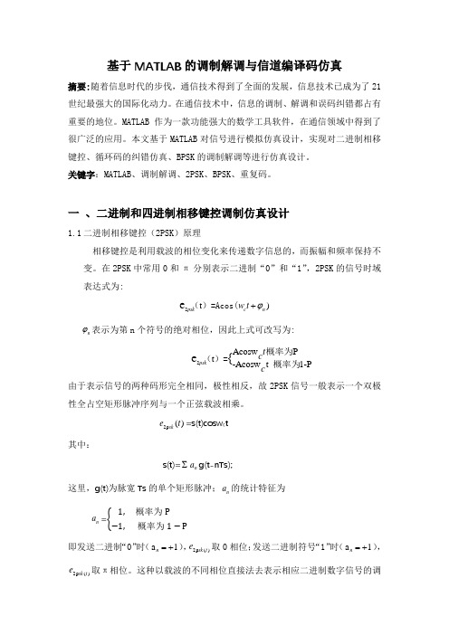
一 、二进制和四进制相移键控调制仿真设计1.1 二进制相移键控(2PSK )原理相移键控是利用载波的相位变化来传递数字信息的,而振幅和频率保持不变。
在2PSK 中常用0和π分别表示二进制“0”和“1”,2PSK 的信号时域表达式为:2t )e c pskn w t ϕ+()=Acos( n ϕ表示为第n 个符号的绝对相位,因此上式可改写为:2Acosw t -Acosw t 1-P Pe {psk c c t ()=概为概率为率 由于表示信号的两种码形完全相同,极性相反,故2PSK 信号一般表示一个双极性全占空矩形脉冲序列与一个正弦载波相乘。
2p ()sk e t =s(t)cosw c t其中:s(t)=∑n a g(t-nTs);这里,g(t)为脉宽Ts 的单个矩形脉冲;n a 的统计特征为 n a =概率为 概率为即发送二进制“0”时(a 1n =+),2p ()sk t e 取0相位;发送二进制符号“1”时(a 1n =+),2p()sk t e 取π相位。
这种以载波的不同相位直接法去表示相应二进制数字信号的调制方式,称为二进制绝对相移方式。
2PSK信号时间波形2PSK信号的调制原理如下图所示,与2ASK的产生方法相比,只是对s(t)的要求不同,在2ASK中s(t)是单极性的,而在2PSK中s(t)是双极性的基带信号。
(a)模拟调制方法(b)键控法2PSK信号的解调通常采用相干解调法,解调原理如下原理框图所示,在相干解调中,如何得到与接受的2PSK信号同频同相的相干载是关键问题,后续进一步介绍。
毕业设计(论文)基于matlab的数字基带通信系统仿真
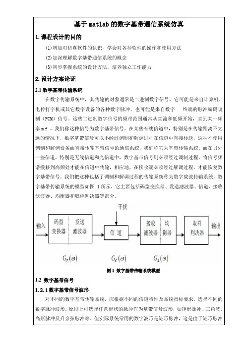
基于matlab的数字基带通信系统仿真1.课程设计的目的(1)增加对仿真软件的认识,学会对各种软件的操作和使用方法(2)加深理解数字基带通信系统的概念(3)初步掌握系统的设计方法,培养独立工作能力2.设计方案论证2.1数字基带传输系统在数字传输系统中,其传输的对象通常是二进制数字信号,它可能是来自计算机、电传打字机或其它数字设备的各种数字脉冲,也可能是来自数字终端的脉冲编码调制(PCM)信号。
这些二进制数字信号的频带范围通常从直流和低频开始,直到某一频率m f ,我们称这种信号为数字基带信号。
在某些有线信道中,特别是在传输距离不太远的情况下,数字基带信号可以不经过调制和解调过程在信道中直接传送,这种不使用调制和解调设备而直接传输基带信号的通信系统,我们称它为基带传输系统。
而在另外一些信道,特别是无线信道和光信道中,数字基带信号则必须经过调制过程,将信号频谱搬移到高频处才能在信道中传输,相应地,在接收端必须经过解调过程,才能恢复数字基带信号。
我们把这种包括了调制和解调过程的传输系统称为数字载波传输系统。
数字基带传输系统的模型如图 1所示,它主要包括码型变换器、发送滤波器、信道、接收滤波器、均衡器和取样判决器等部分。
图1 数字基带传输系统模型1.2 数字基带信号1.2.1数字基带信号波形对不同的数字基带传输系统,应根据不同的信道特性及系统指标要求,选择不同的数字脉冲波形。
原则上可选择任意形状的脉冲作为基带信号波形,如矩形脉冲、三角波、高斯脉冲及升余弦脉冲等。
但实际系统常用的数字波形是矩形脉冲,这是由于矩形脉冲纤数字传输系统中的线路传输码型。
此外,CMI 码和曼彻斯特码一样都是将一位二进制码用一组两位二进制码表示,因此称其为1B2B 码。
(5)4B/3T 码4B/3T 码是1B/1T 码的改进型它把4 个二进制码元变换为3个三进制码元。
显然,在相同信息速率的条件下,4B/3T 码的码元传输速率要比1B/1T 码的低,因而提高了系统的传输效率。
数据通信 毕业论文外文文献英文翻译

郑州轻工业学院本科毕业设计(论文)——英文翻译题目差错控制编码解决加性噪声的仿真学生姓名专业班级通信工程05-2 学号 12院(系)计算机与通信工程学院指导教师完成时间 2009年4月26日英文原文:Data communicationsGildas Avoine and Philippe OechslinEPFL, Lausanne, Switzerlandfgildas.avoine, philippe.oechsling@ep.chAbstractData communications are communications and computer technology resulting from the combination of a new means of communication. To transfer information between the two places must have transmission channel, according to the different transmission media, there is wired data communications and wireless data communications division. But they are through the transmission channel data link terminals and computers, different locations of implementation of the data terminal software and hardware and the sharing of information resources.1 The development of data communicationsThe first phase: the main language, through the human, horsepower, war and other means of transmission of original information.Phase II: Letter Post. (An increase means the dissemination of information)The third stage: printing. (Expand the scope of information dissemination)Phase IV: telegraph, telephone, radio. (Electric to enter the time)Fifth stage: the information age, with the exception of language information, there are data, images, text and so on.1.1 The history of modern data communicationsCommunication as a Telecommunications are from the 19th century, the beginning Year 30. Faraday discovered electromagnetic induction in 1831. Morse invented telegraph in 1837. Maxwell's electromagnetic theory in 1833. Bell invented the telephone in 1876. Marconi invented radio in 1895. Telecom has opened up in the new era. Tube invented in 1906 in order to simulate the development of communications.Sampling theorem of Nyquist criteria In 1928. Shannong theorem in 1948. The invention of the 20th century, thesemiconductor 50, thereby the development of digital communications. During the 20th century, the invention of integrated circuits 60. Made during the 20th century, 40 the concept of geostationary satellites, but can not be achieved. During the 20th century, space technology 50. Implementation in 1963 first synchronized satellite communications. The invention of the 20th century, 60 laser, intended to be used for communications, was not successful. 70 The invention of the 20th century, optical fiber, optical fiber communications can be developed.1.2 Key figuresBell (1847-1922), English, job in London in 1868. In 1871 to work in Boston. In 1873, he was appointed professor at Boston University. In 1875, invented many Telegram Rd. In 1876, invented the telephone. Lot of patents have been life. Yes, a deaf wife.Marconi (1874-1937), Italian people, in 1894, the pilot at his father's estate. 1896, to London. In 1897, the company set up the radio reported. In 1899, the first time the British and French wireless communications. 1916, implementation of short-wave radio communications. 1929, set up a global wireless communications network. Kim won the Nobel Prize. Took part in the Fascist Party.1.3 Classification of Communication SystemsAccording to type of information: Telephone communication system, Cable television system ,Data communication systems.Modulation by sub: Baseband transmission,Modulation transfer.Characteristics of transmission signals in accordance with sub: Analog Communication System ,Digital communication system.Transmission means of communication system: Cable Communications,Twisted pair, coaxial cable and so on.And long-distance telephone communication. Modulation: SSB / FDM. Based on the PCM time division multiple coaxial digital base-band transmission technology. Will gradually replace the coaxial fiber.Microwave relay communications:Comparison of coaxial and easy to set up, low investment, short-cycle. Analog phone microwave communications mainly SSB / FM /FDM modulation, communication capacity of 6,000 road / Channel. Digital microwave using BPSK, QPSK and QAM modulation techniques. The use of 64QAM, 256QAM such as multi-level modulation technique enhance the capacity of microwave communications can be transmitted at 40M Channel 1920 ~ 7680 Telephone Rd PCM figure.Optical Fiber Communication: Optical fiber communication is the use of lasers in optical fiber transmission characteristics of long-distance with a large communication capacity, communication, long distance and strong anti-interference characteristics. Currently used for local, long distance, trunk transmission, and progressive development of fiber-optic communications network users. At present, based on the long-wave lasers and single-mode optical fiber, each fiber road approach more than 10,000 calls, optical fiber communication itself is very strong force. Over the past decades, optical fiber communication technology develops very quickly, and there is a variety of applications, access devices, photoelectric conversion equipment, transmission equipment, switching equipment, network equipment and so on. Fiber-optic communications equipment has photoelectric conversion module and digital signal processing unit is composed of two parts.Satellite communications: Distance communications, transmission capacity, coverage, and not subject to geographical constraints and high reliability. At present, the use of sophisticated techniques Analog modulation, frequency division multiplexing and frequency division multiple access. Digital satellite communication using digital modulation, time division multiple road in time division multiple access.Mobile Communications: GSM, CDMA. Number of key technologies for mobile communications: modulation techniques, error correction coding and digital voice encoding. Data Communication Systems.1.4 Five basic types of data communication system:(1)Off-line data transmission is simply the use of a telephone or similar link to transmit data without involving a computer system.The equipment used at both ends of such a link is not part of a computer, or at least does not immediately make the data available for computer process, that is, the data when sent and / or received are 'off-line'.This type of data communication is relatively cheap and simple.(2)Remote batch is the term used for the way in which data communication technology is used geographically to separate the input and / or output of data from the computer on which they are processed in batch mode.(3)On-line data collection is the method of using communications technology to provide input data to a computer as such input arises-the data are then stored in the computer (say on a magnetic disk) and processed either at predetermined intervals or as required.(4)Enquiry-response systems provide, as the term suggests, the facility for a user to extract information from a computer.The enquiry facility is passive, that is, does not modify the information stored.The interrogation may be simple, for example, 'RETRIEVE THE RECORD FOR EMPLOYEE NUMBER 1234 'or complex.Such systems may use terminals producing hard copy and / or visual displays.(5)Real-time systems are those in which information is made available to and processed by a computer system in a dynamic manner so that either the computer may cause action to be taken to influence events as they occur (for example as in a process control application) or human operators may be influenced by the accurate and up-to-date information stored in the computer, for example as in reservation systems.2 Signal spectrum with bandwidthElectromagnetic data signals are encoded, the signal to be included in the data transmission. Signal in time for the general argument to show the message (or data) as a parameter (amplitude, frequency or phase) as the dependent variable. Signal of their value since the time variables are or not continuous, can be divided into continuous signals and discrete signals; according to whether the values of the dependent variable continuous, can be divided into analog signals and digital Signal.Signals with time-domain and frequency domain performance of the two most basic forms and features. Time-domain signal over time to reflect changing circumstances. Frequency domain characteristics of signals not only contain the same information domain, and the spectrum of signal analysis, can also be a clear understanding of the distribution ofthe signal spectrum and share the bandwidth. In order to receive the signal transmission and receiving equipment on the request channel, Only know the time-domain characteristics of the signal is not enough, it is also necessary to know the distribution of the signal spectrum. Time-domain characteristics of signals to show the letter .It’s changes over time. Because most of the signal energy is concentrated in a relatively narrow band, so most of our energy focused on the signal that Paragraph referred to as the effective band Bandwidth, or bandwidth. Have any signal bandwidth. In general, the greater the bandwidth of the signal using this signal to send data Rate on the higher bandwidth requirements of transmission medium greater. We will introduce the following simple common signal and bandwidth of the spectrum.More or less the voice signal spectrum at 20 Hz ~ 2000 kHz range (below 20 Hz infrasound signals for higher than 2000 KHz. For the ultrasonic signal), but with a much narrower bandwidth of the voice can produce an acceptable return, and the standard voice-frequency signal gnal 0 ~ 4 MHz, so the bandwidth of 4 MHz.As a special example of the monostable pulse infinite bandwidth. As for the binary signal, the bandwidth depends on the generalThe exact shape of the signal waveform, as well as the order of 0,1. The greater the bandwidth of the signal, it more faithfully express the number of sequences.3 The cut-off frequency channel with bandwidthAccording to Fourier series we know that if a signal for all frequency components can be completely the same through the transmission channel to the receiving end, then at the receiving frequency components of these formed by stacking up the signal and send the signal side are exactly the same, That is fully recovered from the receiving end of the send-side signals. But on the real world, there is no channel to no wear and tear through all the Frequency components. If all the Fourier components are equivalent attenuation, then the signal reception while Receive termination at an amplitude up Attenuation, but the distortion did not happen. However, all the transmission channel and equipment for different frequency components of the degree of attenuation is differentSome frequency components almost no attenuation, and attenuation of some frequency components by anumber, that is to say, channel also has a certain amount of vibrationIncrease the frequency characteristics, resulting in output signal distortion. Usually are frequency of 0 Hz to fc-wide channel at Chuan harmonic lost during the attenuation does not occur (or are a very small attenuation constant), whereas in the fc frequency harmonics at all above the transmission cross Decay process a lot, we put the signal in the transmission channel of the amplitude attenuation of a component to the original 0.707(that is, the output signal Reduce by half the power) when the frequency of the corresponding channel known as the cut-off frequency (cut - off frequency).Cut-off frequency transmission medium reflects the inherent physical properties. Other cases, it is because people interested in Line filter is installed to limit the bandwidth used by each user. In some cases, because of the add channel Two-pass filter, which corresponds to two-channel cut-off frequency f1 and f2, they were called up under the cut-off frequency and the cut-off frequency.This difference between the two cut-off frequency f2-f1 is called the channel bandwidth. If the input signal bandwidth is less than the bandwidth of channel, then the entire input signal Frequency components can be adopted by the Department of channels, which the letter Road to be the output of the output waveform will be true yet. However, if the input signal bandwidth greater than the channel bandwidth, the signal of a Frequency components can not be more on the channel, so that the signal output will be sent with the sending end of the signal is somewhat different, that is produced Distortion. In order to ensure the accuracy of data transmission, we must limit the signal bandwidth.4 Data transfer rateChannel maximum data transfer rate Unit time to be able to transfer binary data transfer rate as the median. Improve data transfer rate means that the space occupied by each Reduce the time that the sequence of binary digital pulse will reduce the cycle time, of course, will also reduce the pulse width.The previous section we already know, even if the binary digital pulse signal through a limited bandwidth channel will also be the ideal generated wave Shape distortion, and when must the input signal bandwidth, the smaller channel bandwidth, output waveformdistortion will be greater. Another angle Degree that when a certain channel bandwidth, the greater the bandwidth of the input signal, the output signal the greater the distortion, so when the data transmissionRate to a certain degree (signal bandwidth increases to a certain extent), in the on-channel output signal from the receiver could not have been Distortion of the output signal sent to recover a number of sequences. That is to say, even for an ideal channel, the limited bandwidth limit System of channel data transfer rate.At early 1924, H. Nyquist (Nyquist) to recognize the basic limitations of this existence, and deduced that the noise-free Limited bandwidth channel maximum data transfer rate formula. In 1948, C. Shannon (Shannon) put into the work of Nyquist 1 Step-by-step expansion of the channel by the random noise interference. Here we do not add on to prove to those now seen as the result of a classic.Nyquist proved that any continuous signal f (t) through a noise-free bandwidth for channel B, its output signal as a Time bandwidth of B continuous signal g (t). If you want to output digital signal, it must be the rate of g (t) for interval Sample. 2B samples per second times faster than are meaningless, because the signal bandwidth B is higher than the high-frequency component other than a letter has been Road decay away. If g (t) by V of discrete levels, namely, the likely outcome of each sample for the V level of a discrete one, The biggest channel data rate Rm ax as follows:Rmax = 2Blog 2 V (bit / s)For example, a 3000 Hz noise bandwidth of the channel should not transmit rate of more than 6,000 bits / second binary digital signal.In front of us considered only the ideal noise-free channel. There is noise in the channel, the situation will rapidly deteriorate. Channel Thermal noise with signal power and noise power ratio to measure the signal power and noise power as the signal-to-noise ratio (S ignal - to -- Noise Ratio). If we express the signal power S, and N express the noise power, while signal to noise ratio should be expressed as S / N. However, people Usually do not use the absolute value of signal to noise ratio, but the use of 10 lo g1 0S / N to indicate the units are decibels (d B). For the S / N equal 10 Channel, said its signal to noise ratio for the 1 0 d B; the same token, if the channel S / N equal to one hundred, then the signal to noiseratio for the 2 0 d B; And so on. S hannon noise channel has about the maximum data rate of the conclusions are: The bandwidth for the BH z, signal to noise ratio for the S / N Channel, the maximum data rate Rm ax as follows:Rmax = Blog 2 (1 + S / N) (bits / second)For example, for a bandwidth of 3 kHz, signal to noise ratio of 30 dB for the channel, regardless of their use to quantify the number of levels, nor Fast sampling rate control, the data transfer rate can not be greater than 30,000 bits / second. S h a n n o n the conclusions are derived based on information theory Out for a very wide scope, in order to go beyond this conclusion, like you want to invent perpetual motion machine, as it is almost impossible.It is worth noting that, S hannon conclusions give only a theoretical limit, and in fact, we should be pretty near the limit Difficult.SUMMARYMessage signals are (or data) of a magnetic encoder, the signal contains the message to be transmitted. Signal according to the dependent variable Whether or not a row of values, can be classified into analog signals and digital signals, the corresponding communication can be divided into analog communication and digital communication.Fourier has proven: any signal (either analog or digital signal) are different types of harmonic frequencies Composed of any signal has a corresponding bandwidth. And any transmission channel signal attenuation signals will, therefore, Channel transmission of any signal at all, there is a data transfer rate limitations, and this is Chengkui N yquist (Nyquist) theorem and S hannon (Shannon) theorem tells us to conclusions.Transmission medium of computer networks and communication are the most basic part of it at the cost of the entire computer network in a very Large proportion. In order to improve the utilization of transmission medium, we can use multiplexing. Frequency division multiplexing technology has many Road multiplexing, wave division multiplexing and TDM three that they use on different occasions.Data exchange technologies such as circuit switching, packet switching and packetswitching three have their respective advantages and disadvantages. M odem are at Analog phone line for the computer's binary data transmission equipment. Modem AM modulation methods have, FM, phase modulation and quadrature amplitude modulation, and M odem also supports data compression and error control. The concept of data communications Data communication is based on "data" for business communications systems, data are pre-agreed with a good meaning of numbers, letters or symbols and their combinations.参考文献[1]C.Y.Huang and A.Polydoros,“Two small SNR classification rules for CPM,”inProc.IEEE Milcom,vol.3,San Diego,CA,USA,Oct.1992,pp.1236–1240.[2]“Envelope-based classification schemes for continuous-phase binary Frequency-shift-keyed modulations,”in Pr oc.IEEE Milcom,vol.3,Fort Monmouth,NJ,USA,Oct.1994,pp. 796–800.[3]A.E.El-Mahdy and N.M.Namazi,“Classification of multiple M-ary frequency-shift keying over a rayleigh fading channel,”IEEE m.,vol.50,no.6,pp.967–974,June 2002.[4]Consulative Committee for Space Data Systems(CCSDS),Radio Frequency and Modulation SDS,2001,no.401.[5]E.E.Azzouz and A.K.Nandi,“Procedure for automatic recognition of analogue and digital modulations,”IEE mun,vol.143,no.5,pp.259–266,Oct.1996.[6]A.Puengn im,T.Robert,N.Thomas,and J.Vidal,“Hidden Markov models for digital modulation classification in unknown ISI channels,”in Eusipco2007,Poznan,Poland, September 2007,pp.1882–1885.[7]E.Vassalo and M.Visintin,“Carrier phase synchronization for GMSK signals,”I nt.J.Satell. Commun.,vol.20,no.6,pp.391–415,Nov.2002.[8]J.G.Proakis,Digital Communications.Mc Graw Hill,2001.[9]L.Rabiner,“A tutorial on hidden Markov models and selected applications in speechrecognition,”Proc.IEEE,vol.77,no.2,pp.257–286,1989.英文译文:数据通信Gildas Avoine and Philippe OechslinEPFL, Lausanne, Switzerlandfgildas.avoine, philippe.oechsling@ep.ch摘要数据通信是通信技术和计算机技术相结合而产生的一种新的通信方式。
基于MATLAB的PSK调制与解调的仿真
基于MATLAB的PSK调制与解调的仿真一、课题说明现代社会发展要求通信系统功能越来越强,性能越来越高,构成越来越复杂;另一方面,要求通信系统技术研究和产品开发缩短周期,降低成本,提高水平。
这样尖锐对立的两个方面的要求,只有通过使用强大的计算机辅助分析设计技术和工具才能实现。
通信系统仿真贯穿通信系统工程设计的全过程,对通信系统的发展起着举足轻重的作用。
本报告针对通信系统仿真的探讨主要做了以下的工作:(1)介绍了通信系统仿真的相关内容,包括通信系统仿真的一般步骤。
(2)对通信系统中的主要环节,如模拟信号的数字传输系统进行了详细的阐述。
(3)在理解通信系统理论的基础上,利用Simulink强大的仿真功能,对PSK通信系统进行了模型构建、系统设计、仿真演示、结果显示,并且给出了具体的分析。
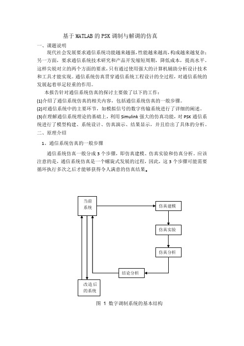
二、原理介绍1、通信系统仿真的一般步骤通信系统仿真一般分成3个步骤,即仿真建模、仿真实验和仿真分析。
应该注意的是,通信系统仿真是一个螺旋式发展的过程,因此,这3个步骤可能需要循环执行多次之后才能够获得令人满意的仿真结果。
图1 数字调制系统的基本结构2、数字频带传输系统在数字基带传输系统中,为了使数字基带信号能够在信道中传输,要求信道应具有低通形式的传输特性。
然而,在实际信道中,大多数信道具有带通传输特性,数字基带信号不能直接在这种带通传输特性的信道中传输。
必须用数字基带信号对载波进行调制,产生各种已调数字信号。
图2 数字调制系统的基本结构3、PSK调制系统3.1 2PSK数字调制原理在二进制数字调制中,当正弦载波的相位随二进制数字基带信号离散变化时,则产生二进制移相键控(2PSK)信号. 通常用已调信号载波的0°和180°分别表示二进制数字基带信号的 1 和0.3.2 2PSK原理图图32PSK信号的调制原理图图42PSK信号的解调原理图三、数字通信2PSK系统建模1、建模基本步骤通信系统仿真的基本步骤如下:(1)建立数学模型:根据通信系统的基本原理,确定总的系统功能,并将各部分功能模块化,找出各部分之间的关系。
- 1、下载文档前请自行甄别文档内容的完整性,平台不提供额外的编辑、内容补充、找答案等附加服务。
- 2、"仅部分预览"的文档,不可在线预览部分如存在完整性等问题,可反馈申请退款(可完整预览的文档不适用该条件!)。
- 3、如文档侵犯您的权益,请联系客服反馈,我们会尽快为您处理(人工客服工作时间:9:00-18:30)。
Review of UMTS1.1 UMTS Network ArchitectureThe European/Japanese 3G standard is referred to as UMTS. UMTS is one of a number of standards ratified by the ITU-T under the umbrella of IMT-2000. It is currently the dominant standard, with the US CDMA2000 standard gaining ground, particularly with operators that have deployed cdmaOne as their 2G technology. At time of writing,Japan is the most advanced in terms of 3G network deployment. The three incumbent operators there have implemented three different technologies: J-Phone is using UMTS,KDDI has a CDMA2000 network, and the largest operator NTT DoCoMo is using a system branded as FOMA (Freedom of Multimedia Access). FOMA is based on the original UMTS proposal, prior to its harmonization and standardization.The UMTS standard is specified as a migration from the second generation GSM standard to UMTS via the General Packet Radio System (GPRS) and Enhanced Data for Global Evolution (EDGE), as shown in Figure. This is a sound rationale since as of April 2003, there were over 847 Million GSM subscribers worldwide1, accounting for68% of the global cellular subscriber figures. The emphasis is on keeping as much ofthe GSM network as possible to operate with the new system.We are now well on the road towards Third Generation (3G), where the network will support all traffic types: voice, video and data, and we should see an eventual explosion in the services available on the mobile device. The driving technology for this is the IP protocol. Many cellular operators are now at a position referred to as 2.5G, with the deployment of GPRS, which introduces an IP backbone into the mobile core network.The diagram below, Figure 2, shows an overview of the key components in a GPRS network, and how it fits into the existing GSM infrastructure.The interface between the SGSN and GGSN is known as the Gn interfaceand uses the GPRS tunneling protocol (GTP, discussed later). The primary reason for the introduction of this infrastructure is to offer connections to external packet networks, such as the Internet or a corporate Intranet.This brings the IP protocol into the network as a transport between the SGSN and GGSN. This allows data services such as email or web browsing on the mobile device,with users being charged based on volume of data rather than time connected.The dominant standard for delivery of 3G networks and services is the Universal Mobile Telecommunications System, or UMTS. The first deployment of UMTS is the Release ’99 architecture, shown below in Figure 3.In this network, the major change is in the radio access network (RAN) with the introduction of CDMA technology for the air interface, and ATM as a transport in the transmission part. These changes have been introduced principally to support the transport of voice, video and data services on the same network. The core network remains relatively unchanged, with primarily software upgrades. However, the IP protocol pushes further into the network with the RNC now communicating with the 3G SGSN using IP.The next evolution step is the Release 4 architecture, Figure 4. Here, the GSM core is replaced with an IP network infrastructure based around V oice over IP technology.The MSC evolves into two separate components: a Media Gateway (MGW) and an MSC Server (MSS). This essentially breaks apart the roles of connection and connection control. An MSS can handle multiple MGWs, making the network more scaleable.Since there are now a number of IP clouds in the 3G network, it makes sense to merge these together into one IP or IP/ATM backbone (it is likely both options will be available to operators.) This extends IP right across the whole network, all the way to the BTS.This is referred to as the All-IP network, or the Release 5 architecture, as shown in Figure 5. The HLR/VLR/EIR are generalised and referred to as the HLR Subsystem(HSS).Now the last remnants of traditional telecommunications switching are removed, leaving a network operating completely on the IP protocol, and generalised for the transport of many service types. Real-time services are supported through the introduction of a new network domain, the IP Multimedia Subsystem (IMS).Currently the 3GPP are working on Release 6, which purports to cover all aspects not addressed in frozen releases. Some call UMTS Release 6 4G and it includes such issues as interworking of hot spot radio access technologies such as wireless LAN1.2 UMTS FDD and TDDLike any CDMA system, UMTS needs a wide frequency band in which to operate to effectively spread signals. The defining characteristic of the system is the chip rate, where a chip is the width of one symbol of the CDMA code. UMTS uses a chip rate of 3.84Mchips/s and this converts to a required spectrum carrier of 5MHz wide. Since this is wider than the 1.25MHz needed for the existi ng cdmaOne system, the UMTS air interface is termed ‘wideband’ CDMA.There are actually two radio technologies under the UMTS umbrella: UMTS FDD and TDD. FDD stands for Frequency Division Duplex, and like GSM, separates traffic in the uplink and downlink by placing them at different frequency channels. Therefore an operator must have a pair of frequencies allocated to allow them to run a network, hence the term ‘paired spectrum’. TDD or Time Division Duplex requires only one frequency channel, and uplink and downlink traffic are separated by sending them at different times. The ITU-T spectrum usage, as shown in Figure 6, for FDD is 1920- 980MHz for uplink traffic, and 2110-2170MHz for downlink. The minimum allocation an operator needs is two paired 5MHz channels, one for uplink and one for downlink, at a separation of 190MHz. However, to provide comprehensive coverage and services, it is recommended that an operator be given three channels. Considering the spectrum allocation, there are 12 paired channels available, and many countries have now completed the licencing process for this spectrum, allocating between two and four channels per licence. This has tended to workout a costly process for operators, since the regulatory authorities in some countries, notably in Europe, have auctioned these licences to the highest bidder. This has resulted in spectrum fees as high as tens of billions of dollars in some countries.The Time Division Duplex (TDD) system, which needs only one 5MHz band in which to operate, often referred to as unpaired spectrum. The differences between UMTS FDD and TDD are only evident at the lower layers, particularly on the radio interface. At higher layers, the bulk of the operation of the two systems is the same. As the name suggests, the TDD system separates uplink and downlink traffic by placing them in different time slots. As will be seen later, UMTS uses a 10ms frame structure which is divided into 15 equal timeslots. TDD can allocate these to be either uplink or downlink,with one or more breakpoints between the two in a frame defined. In this way, it is well suited to packet traffic, since this allows great flexibility in dynamically dimensioning for asymmetry in traffic flow.The TDD system should not really be considered as an independent network, but rather as a supplement for an FDD system to provide hotspot coverage at higher data rates. It is rather unsuitable for large scale deployment due to interference between sites, since a BTS may be trying to detect a weak signal from a UE, which is blocked out by a relatively strong signal at the same frequency from a nearby BTS. TDD is ideal for indoor coverage over small areas.Since FDD is the main access technology being developed currently, the explanations presented here will focus purely on this system.1.3 UMTS Bearer ModelThe procedures of a mobile device connecting to a UMTS network can be split into two areas: the access stratum (AS) and the non-access stratum (NAS). The access stratum involves all the layers and subsystems that offer general services to the non-access stratum. In UMTS, the access stratum consists of all of the elements in the radio access network, including the underlying ATMtransport network, and the various mechanisms such as those to provide reliable information exchange. All of the non-access stratum functions are those between the mobile device and the core network, for example, mobility management. Figure 7 shows the architecture model. The AS interacts with the NAS through the use of service access points (SAPs).UMTS radio access network (UTRAN) provides this separation of NAS and AS functions, and allows for AS functions to be fully controlled and implemented within the UTRAN. The two major UTRAN interfaces are the Uu, which is the interface between the mobile device, or User Equipment (UE) and the UTRAN, and the Iu, which is the interface between the UTRAN and the core network. Both of these interfaces can be divided into control and user planes each with appropriate protocol functions.A Bearer Service is a link between two points, which is defined by a certain set of characteristics. In the case of UMTS, the bearer service is delivered using radio access bearers.A Radio access bearer (RAB) is defined as the service that the access stratum (i.e.UTRAN) provides to the non-access stratum for transfer of user data between the User Equipment and Core Network. A RAB can consist of a number of subflows, which are data streams to the core network within the RAB that have different QoS characteristics,such as different reliabilities. A common example of this is different classes of bits with different bit error rates can be realised as different RAB subflows. RAB subflows are established and released at the time the RAB is established and released, and are delivered together over the same transport bearer.A Radio Link is defined as a logical association between a single User Equipment (UE) and a single UTRAN access point, such as an RNC. It is physically comprised of one or more radio bearers and should not be confused with radio access bearer.Looking within the UTRAN, the general architecture model is as shown in Figure 8 below. Now shown are the Node B or Base Station (BTS) and RadioNetwork Controller (RNC) components, and their respective internal interfaces. The UTRAN is subdivided into blocks referred to as Radio Network Subsystems (RNS), where each RNS consists of one controlling RNC (CRNC) and all the BTSs under its control. Unique to UMTS is the interface between RNSs, the Iur interface, which plays a key role in handover procedures. The interface between the BTS and RNC is the Iub interface.All the ‘I’ interfaces: Iu, Iur and Iub, currently3 use ATM as a transport layer. In the context of ATM, the BTS is seen as a host accessing an ATM network, within which the RNC is an ATM switch. Therefore, the Iub is a UNI interface, whereas the Iu and Iur interfaces are considered to be NNI, as illustrated in Figure 9.This distinction is because the BTS to RNC link is a point-to-point connection in that a BTS or RNC will only communicate with the RNC or BTS directly connected to it, and will not require communication beyond that element to another network element.For each user connection to the core network, there is only one RNC, which maintains the link between the UE and core network domain, as highlighted in Figure 10. This RNC is referred to as the serving RNC or SRNC. That SRNC plus the BTSs under its control is then referred to as the SRNS. This is a logical definition with reference to that UE only. In an RNS, the RNC that controls a BTS is known as the controlling RNC or CRNC. This is with reference to the BTS, cells under its control and all the common and shared channels within.As the UE moves, it may perform a soft or hard handover to another cell. In the case of a soft handover, the SRNC will activate the new connection to the new BTS. Should the new BTS be under the control of another RNC, the SRNC will also alert this new RNC to activate a connection along the Iur interface. The UE now has two links, one directly to the SRNC, and the second, through the new RNC along the Iur interface. In this case, this new RNC is logically referred to as a drift RNC or DRNC, see Figure 10. It is not involved in any processing of the call and merely relays it to the SRNC for connection to the core. In summary,SRNC and DRNC are usually associated with the UE and the CRNC is associated with the BTS. Since these are logical functions it is normal practice that a single RNC is capable of dealing with all these functions.A situation may arise where a UE is connected to a BTS for which the SRNC is not the CRNC for that BTS. In that situation, the network may invoke the Serving RNC Relocation procedure to move the core network connection. This process is described inSection 3.通用移动通信系统的回顾1.1 UMTS网络架构欧洲/日本的3G标准,被称为UMTS。