Limisprox 系列限位开关
限位开关工作原理

限位开关工作原理限位开关是一种常用的电气控制元件,它在机械设备和自动化系统中起着非常重要的作用。
它的工作原理是通过机械触点或电子传感器来检测物体的位置,从而控制设备的运行状态。
本文将从限位开关的工作原理入手,详细介绍其工作原理和应用。
1. 限位开关的基本原理。
限位开关的基本原理是利用物体的位置来控制设备的运行状态。
它通常由一个开关和一个触发装置组成。
当物体接触到限位开关的触发装置时,开关会打开或关闭,从而触发设备的相应动作。
限位开关可以根据其触发装置的不同分为机械式限位开关和电子式限位开关。
机械式限位开关通常采用机械触点来实现物体位置的检测。
当物体接触到机械触点时,触点会闭合或断开,从而触发设备的运行状态。
电子式限位开关则采用电子传感器来实现物体位置的检测。
它通过光电、电容、电感等原理来检测物体的位置,具有灵敏度高、寿命长等优点。
2. 限位开关的工作原理。
限位开关的工作原理可以用一个简单的实例来说明。
假设有一个自动门,我们需要通过限位开关来控制门的开关状态。
当门关闭时,门上方安装了一个限位开关,当有人靠近门时,身体会触发限位开关,限位开关会感应到物体的位置,从而打开门。
当人离开门后,限位开关再次感应到物体的位置,门会自动关闭。
这个例子就展示了限位开关通过检测物体的位置来控制设备的运行状态的基本原理。
3. 限位开关的应用。
限位开关在工业自动化领域有着广泛的应用。
它可以用于控制机械设备的起停、位置检测、物料输送等。
在自动化生产线上,限位开关可以用于检测产品的位置,从而实现自动分拣和装配。
在机械加工设备上,限位开关可以用于控制工件的加工位置和加工深度。
在输送设备上,限位开关可以用于控制物料的输送方向和速度。
除了工业领域,限位开关还广泛应用于家用电器、汽车电子、航空航天等领域。
在家用电器中,限位开关可以用于控制家电设备的开关状态,比如洗衣机的盖子开关、微波炉的门离开开关等。
在汽车电子中,限位开关可以用于控制汽车门窗的开关状态,汽车座椅的调节位置等。
电气neumatic限位开关、阀门配件说明说明书
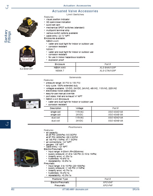
S a n i t a r y F i t t i n g sJ652DPL418877.963.4966 • Actuated Valve AccessoriesLimit SwitchesSolenoidsPositionersFeatures:• air capacity:at 29 PSI (200kPa): 9.5 SCFM at 87 PSI (600kPa): 28.3 SCFM at 145 PSI (1MPa): 47.1 SCFM • air connections: 1/4" NPT • gauges: 1/8" NPT • cable entry: 1/2" NPT Electro-Pneumatic• input range: 4-20mA (Ri<250ohms)• supply pressure: 21.8 to 145 PSI (0.15 to 1MPa) • linearity error: <1.0% f.s • hysteresis: <0.6% f.s • repeatability: <0.5% f.s Pneumatic• input range: 3 to 15 PSI (20-100kPa) • supply pressure: < 145 PSI (<1MPa) • linearity error: <0.7% f.s • hysteresis: <0.4% f.s • repeatability: <0.3% f.sPositioner Type Part #Electro-PneumaticXPO-E4F PneumaticXPO-P4FFeatures:• pressure range: 30 PSI to 150 PSI • duty cycle: 100% extended duty• voltages available: 12VDC, 24VDC, 24VAC, 48VAC, 110VAC, 220VAC • electroless nickel plated spool • easy-to-use manual override• port sizes: inlet and exhaust ¼" NPT • NEMA 4 4/X Enclosure• water and dust tight for indoor or outdoor use • corrosion resistantDescription Voltage Part #single coil 115VAC XSO-4S4D-0A single coil 24VDC XSO-4S4B-0A dual coil 115VAC XSO-4D4D-0A dual coil24VDCXSO-4D4B-0AFeatures:• visual position indicator • 3D open/close indication • quick-set cam• mechanical SPDT switches (standard)• multipoint terminal strip• various switch options available • cable entry: (2) ½" NPT Enclosures available: NEMA 4 4/X• water and dust tight for indoor or outdoor use • corrosion resistant NEMA 7• water and dust tight for indoor or outdoor use • corrosion resistant•for use in indoor hazardous locations • explosion proofEnclosurePart #NEMA 4/4X XLS-B4A0120P NEMA 7XLS-C7A0120PActuation: AccessoriesXLS-B4A0120P。
限位开关工作原理

限位开关工作原理
限位开关是一种用来检测或控制机械设备运动终点位置的重要元件。
它在工业
自动化控制系统中起着至关重要的作用。
限位开关的工作原理主要是通过机械触点或非接触式传感器来实现,下面将详细介绍限位开关的工作原理及其应用。
首先,限位开关的工作原理是基于机械触点的。
当被控对象达到设定的位置时,机械触点会被触发,产生一个开关信号,从而控制设备的停止或转向。
这种类型的限位开关通常由金属触点和弹簧构成,当被控对象触碰到触点时,触点会闭合或打开,从而改变电路的通断状态,实现对设备的控制。
其次,限位开关还可以采用非接触式传感器来实现。
非接触式传感器通常采用
光电、超声波、电容等原理,当被控对象接近传感器时,传感器会感知到并产生相应的信号。
这种类型的限位开关具有高精度、长寿命、不易受环境影响等优点,广泛应用于精密设备和特殊环境中。
限位开关在工业自动化控制系统中有着广泛的应用。
它可以用来检测设备的位置、控制设备的运动方向、保护设备的安全等。
例如,在自动化生产线上,限位开关可以用来检测产品的位置,控制机械手的动作,确保产品的准确装配;在起重设备上,限位开关可以用来检测吊钩的位置,避免超载或碰撞等危险情况的发生。
总的来说,限位开关通过机械触点或非接触式传感器来实现对设备位置的检测
和控制。
它在工业自动化领域起着至关重要的作用,为生产和操作提供了可靠的保障。
随着科技的不断发展,限位开关的工作原理和应用也在不断创新和完善,将为工业自动化带来更多的便利和效益。
Soliphant T FTM20、FTM21级别限位开关说明书

TI389F/24/aeTechnical InformationSoliphant T FTM20, FTM21Level limit switchRobust vibration limit switch for bulk solids,also for dust incendive hazardous areasApplicationSoliphant T is a robust level limit switch for silos with fine-grained or coarse-grained, non-fluid bulk solids.Multiple designs allow the device to be used in various applications. Certificates are also available for use in dust incendive hazardous areas.FTM20: compact design, 10" (250 mm) with vibrating rod for installation in any direction.FTM21: vibrating rod with extension pipe -20 in, 40 in, or 60 in (500 mm, 1000 mm, 1500 mm)for installation in any orientation.Typical applications include: cereals, coffee beans, sugar, animal feed, rice, detergents, dye powder, chalk, gypsum, cement, sand, plastic granules, etc.Your benefits•No calibration: easy commissioning•Insensitive to build-up: maintenance-free operation •No mechanically moving parts: no wear, long operating life•Sensor material 316L SS: minimal abrasion even with materials that tend to build up•Plastic housing with cover and sight glass: switch status visible from outside•Aluminum housing also available •Relays or PNP output•Insensitive to external vibration and flow noises •Available with explosion protection including FM or CSA approvalSoliphant T FTM20/FTM212Endress+HauserTable of contentsFunction and system design. . . . . . . . . . . . . . . . . . . . .3Measuring principle . . . . . . . . . . . . . . . . . . . . . . . . . . . . . . . . . . . 3Measuring system . . . . . . . . . . . . . . . . . . . . . . . . . . . . . . . . . . . . . 3Cable specifications. . . . . . . . . . . . . . . . . . . . . . . . . . .3Cable entries . . . . . . . . . . . . . . . . . . . . . . . . . . . . . . . . . . . . . . . . 3Input . . . . . . . . . . . . . . . . . . . . . . . . . . . . . . . . . . . . . .4Measured variable . . . . . . . . . . . . . . . . . . . . . . . . . . . . . . . . . . . . 4Measuring range (application) . . . . . . . . . . . . . . . . . . . . . . . . . . . . 4Input signal . . . . . . . . . . . . . . . . . . . . . . . . . . . . . . . . . . . . . . . . . 4Output. . . . . . . . . . . . . . . . . . . . . . . . . . . . . . . . . . . . .4Switching delay . . . . . . . . . . . . . . . . . . . . . . . . . . . . . . . . . . . . . . 4Switch behavior . . . . . . . . . . . . . . . . . . . . . . . . . . . . . . . . . . . . . 4Fail-safe mode . . . . . . . . . . . . . . . . . . . . . . . . . . . . . . . . . . . . . . . 4FEM22 electronic insert(DC PNP). . . . . . . . . . . . . . . . . . . . . . . . . . . . . . . . . . .5Power supply . . . . . . . . . . . . . . . . . . . . . . . . . . . . . . . . . . . . . . . . 5Electrical connection . . . . . . . . . . . . . . . . . . . . . . . . . . . . . . . . . . 5Output signal . . . . . . . . . . . . . . . . . . . . . . . . . . . . . . . . . . . . . . . . 5Signal on alarm . . . . . . . . . . . . . . . . . . . . . . . . . . . . . . . . . . . . . . 5Connectable load . . . . . . . . . . . . . . . . . . . . . . . . . . . . . . . . . . . . . 5FEM24 electronic insert(AC/DC with relay output) . . . . . . . . . . . . . . . . . . . . .6Power supply . . . . . . . . . . . . . . . . . . . . . . . . . . . . . . . . . . . . . . . . 6Electrical connection . . . . . . . . . . . . . . . . . . . . . . . . . . . . . . . . . . 6Output signal . . . . . . . . . . . . . . . . . . . . . . . . . . . . . . . . . . . . . . . . 6Signal on alarm . . . . . . . . . . . . . . . . . . . . . . . . . . . . . . . . . . . . . . 6Connectable load . . . . . . . . . . . . . . . . . . . . . . . . . . . . . . . . . . . . . 6Performance characteristics. . . . . . . . . . . . . . . . . . . . .7Reference operating conditions . . . . . . . . . . . . . . . . . . . . . . . . . . . 7Measuring frequency . . . . . . . . . . . . . . . . . . . . . . . . . . . . . . . . . . 7Maximum measured error . . . . . . . . . . . . . . . . . . . . . . . . . . . . . . 7Repeatability . . . . . . . . . . . . . . . . . . . . . . . . . . . . . . . . . . . . . . . . . 7Start-up settling time. . . . . . . . . . . . . . . . . . . . . . . . . . . . . . . . . . 7Installation. . . . . . . . . . . . . . . . . . . . . . . . . . . . . . . . . .7Installation instructions . . . . . . . . . . . . . . . . . . . . . . . . . . . . . . . . . 7Environment . . . . . . . . . . . . . . . . . . . . . . . . . . . . . . . .7Ambient temperature range . . . . . . . . . . . . . . . . . . . . . . . . . . . . . 7Storage temperature . . . . . . . . . . . . . . . . . . . . . . . . . . . . . . . . . . . 7Climate class . . . . . . . . . . . . . . . . . . . . . . . . . . . . . . . . . . . . . . . . 7Degree of protection . . . . . . . . . . . . . . . . . . . . . . . . . . . . . . . . . . . 7Electrical safety . . . . . . . . . . . . . . . . . . . . . . . . . . . . . . . . . . . . . . 7Vibration resistance . . . . . . . . . . . . . . . . . . . . . . . . . . . . . . . . . . . 8Electromagnetic compatibility . . . . . . . . . . . . . . . . . . . . . . . . . . . . 8Process . . . . . . . . . . . . . . . . . . . . . . . . . . . . . . . . . . . .8Environment . . . . . . . . . . . . . . . . . . . . . . . . . . . . . . . . . . . . . . . . 8Thermal shock resistance . . . . . . . . . . . . . . . . . . . . . . . . . . . . . . . 8Limiting medium pressure range. . . . . . . . . . . . . . . . . . . . . . . . . 8State of aggregation . . . . . . . . . . . . . . . . . . . . . . . . . . . . . . . . . . . 8Density. . . . . . . . . . . . . . . . . . . . . . . . . . . . . . . . . . . . . . . . . . . . 8Rod lateral load . . . . . . . . . . . . . . . . . . . . . . . . . . . . . . . . . . . . . . 8Pipe lateral load . . . . . . . . . . . . . . . . . . . . . . . . . . . . . . . . . . . . . . 8Mechanical construction . . . . . . . . . . . . . . . . . . . . . . .9Design, dimensions . . . . . . . . . . . . . . . . . . . . . . . . . . . . . . . . . . . 9Weight . . . . . . . . . . . . . . . . . . . . . . . . . . . . . . . . . . . . . . . . . . . 11Material . . . . . . . . . . . . . . . . . . . . . . . . . . . . . . . . . . . . . . . . . . . 11Human interface . . . . . . . . . . . . . . . . . . . . . . . . . . . .11Operating elements . . . . . . . . . . . . . . . . . . . . . . . . . . . . . . . . . . 11Display elements . . . . . . . . . . . . . . . . . . . . . . . . . . . . . . . . . . . . 11Certificates and approvals . . . . . . . . . . . . . . . . . . . . .12CE mark . . . . . . . . . . . . . . . . . . . . . . . . . . . . . . . . . . . . . . . . . . 12Other standards and guidelines . . . . . . . . . . . . . . . . . . . . . . . . . . 12Hazardous area approval . . . . . . . . . . . . . . . . . . . . . . . . . . . . . . 12Type of protection . . . . . . . . . . . . . . . . . . . . . . . . . . . . . . . . . . . 12Ordering information. . . . . . . . . . . . . . . . . . . . . . . . .13Soliphant T FTM20 . . . . . . . . . . . . . . . . . . . . . . . . . . . . . . . . . . 13Soliphant T FTM21 . . . . . . . . . . . . . . . . . . . . . . . . . . . . . . . . . . 13Accessories . . . . . . . . . . . . . . . . . . . . . . . . . . . . . . . .14Soliphant T. . . . . . . . . . . . . . . . . . . . . . . . . . . . . . . . . . . . . . . . 14Spare parts . . . . . . . . . . . . . . . . . . . . . . . . . . . . . . . . . . . . . . . . . 14Documentation . . . . . . . . . . . . . . . . . . . . . . . . . . . . .15Operating Instructions. . . . . . . . . . . . . . . . . . . . . . . . . . . . . . . . 15Soliphant T FTM20/FTM21Function and system designMeasuring principle A piezoelectric drive excites the vibrating rod of the Soliphant T FTM20 and FTM21 to its resonancefrequency.When the medium covers the vibrating rod, the rod's vibrating amplitude changes (the vibration is damped).Soliphant's electronics compare the actual amplitude with a target value and indicates whether the vibratingrod is vibrating freely or whether it is covered by medium.1. Vibrating amplitude with probe vibrating freely2. Vibrating amplitude with probe coveredMeasuring system Soliphant T is a compact electronic switch.The entire measuring system consists of:•Soliphant T FTM20 or FTM21 with FEM22 or FEM24 electronic insert•a power supply and•the connected control systems, switching units, signalling systems (e.g. lamps, horns, PCS, PLC, etc.)Cable specificationsUse a standard commercial cable max. 18 AWG (max. 2.5 mm2).Note!Use a shielded cable in the event of strong electromagnetic radiation.Endress+Hauser3Soliphant T FTM20/FTM214Endress+HauserCable entries ½" NPT (others on request, please consult factory)InputMeasured variable From 12.5 lb/ft 3 (200 g/l) within the length of the sensor.Measuring range (application)The measuring range depends on the mounting location of Soliphant T and the length of the pipe extension selected. The pipe extension is available in the following lengths: 20 in, 40 in, 60 in (500 mm, 1000 mm,1500 mm).Input signalProbes covered => small amplitude of vibrating rod Probe not covered => large amplitude of vibrating rodOutputSwitching delay0.5 s when the sensor is covered 1 s when the sensor is exposed Switch behavior ON/OFFFail-safe modeMinimum/maximum quiescent current safety can be switched at the electronic insert.Max. = maximum safety (high level):When the vibrating rod is covered, the output switches in the direction of the signal on alarm.For example, used for overfill protection.Min. = minimum safety (low level):When the vibrating rod becomes exposed, the output switches in the direction of the signal on alarm For example, used for dry running protection and empty running protection.Soliphant T FTM20/FTM21Endress+Hauser 5FEM22 electronic insert (DC PNP)Power supplyDC voltage 10 V to 45 V Ripple max. 5 V, 0 to 400 HzCurrent consumption max. 18 mA Power consumption max. 0.81 W Reverse polarity protectedFEM22 overvoltage protection: overvoltage category III Electrical connectionThree-wire direct current connection Output signalSignal on alarm Output signal in event of power failure: < 100 μA Connectable loadLoad switched via transistor and separate PNP connection.Max. 45 V (cyclical overload and short-circuit protection);Continuous max. 350 mA;Max. 0.5 μF for 45 V, max. 1.0 μF for 24 V;Residual voltage < 3 V (for transistor switched through);Residual current < 100 μA (for blocked transistor).Preferred in conjunction with programmable logic controllers (PLC),DI modules as per EN 61131-2.Positive signal at electronics switch output (PNP);Output blocked at level limit.IL< 100 μA L00-FTL2xxxx-07-05-xx-xx-000= Load current(switched through)= Residual current(blocked)= Lit = Not litSoliphant T FTM20/FTM216Endress+HauserFEM24 electronic insert (AC/DC with relay output)Power supplyAlternating voltage 19 V to 253 V, 50/60 Hz or DC voltage 19 V to 55 V Power consumption max. 1.3 W Reverse polarity protectionFEM24 overvoltage protection: overvoltage category III Electrical connectionUniversal current connection with relay output Output signalSignal on alarm Output signal in event of power failure: relay de-energized Connectable loadLoads switched via 2 floating change-over contacts.I~ max. 6 A, U~ max. 253 V;P~ max. 1500 VA, cos ϕ = 1, P~ max. 750 VA, cos ϕ > 0.7;I- max. 6 A to 30 V, I- max. 0.2 A to 125 V.The following applies when connecting a functional extra-low voltage circuit with double insulation as per IEC 1010: Sum of voltages of relay output and power supply max. 300 VOutput:When connecting a device withhigh inductance, provide a spark arrester to protect the relay contact.A fine-wire fuse (depending on the load connected) protects the relay contact in the event of a short-circuit.Both relay contacts switch simultaneously.DPDT (double pole double throw)*When jumpered, therelay output works with NPN logic.** Please refer to "Connectable load" section Note! Please note the different voltage ranges for direct and alternating current.L00-FTL2xxxx-07-05-xx-xx-001= Relay energized = Relay de-energized = Lit = Not litSoliphant T FTM20/FTM21Endress+Hauser7Performance characteristicsReference operating conditionsAmbient temperature: 68°F (20°C)Process temperature: 68°F (20°C)Medium: ABS granules 38 to 42 lb/ft 3 (610 to 680 g/l)Grain size: 0.08" to 0.14" (2 to 3.5 mm)Pressure: atmosphericSensor installation: vertical from above or below; horizontal from the side Measuring frequency 700 to 800 Hz Maximum measured error ≤ 0.20" (5 mm)Repeatability < 0.04" (1 mm)Start-up settling time< 3 sInstallationInstallation instructionsMounting locatione.g. storage or buffer container OrientationHorizontal installation/vertical installation* With protective cover (to be provided by customer)** With protecting tube (to be provided by customer)EnvironmentAmbient temperature range -40 to +158°F (-40 to +70°C)Storage temperature -40 to +185°F (-40 to +85°C)Climate class Tropicalized as per DIN IEC 68 Part 2-38Degree of protection NEMA 4X (F18 Aluminum housing), IP66/IP67 (F16, F18 housing)Electrical safetyIEC 61010, CSA 1010.1-92, FM3600Soliphant T FTM20/FTM218Endress+HauserVibration resistanceDIN 60068-2-27 / IEC 68-2-27: shock 50 g; vibration 0.05 g 2/Hz Electromagnetic compatibilityInterference emission to EN 61326, Electrical Equipment Class B Interference immunity to EN 61326, Annex A (Industrial)ProcessEnvironmentPermitted ambient temperature T 1 at housing depending on the medium temperature T 2 in the container:Thermal shock resistance 120 KLimiting medium pressure range-14.5 to 362 psi (-1 to 25 bar)State of aggregation SolidsDensityBulk solids weight: ≥ 12.5 lb/ft 3 (200 g/l), not fluidized Grain size: ≤ 0.98" (25 mm)Rod lateral load ≤ 101 lbf (450 N)Pipe lateral load≤ 22.5 lbf per 3 ft of pipe (160 N per 1 m)Soliphant T FTM20/FTM21Mechanical constructionDesign, dimensions Compact version, aluminum housing, FTM 20Pipe extension, aluminum housing, FTM 21x = 20 in,40 in, or60 in (500 mm,1000 mm,or 1500 mm)Endress+Hauser9Soliphant T FTM20/FTM21 Design, dimensions Compact version, plastic housingPipe extension, plastic housingx = 20 in,40 in, or 60 in (500 mm,1000 mm, or1500 mm)10Endress+HauserEndress+Hauser 11Weight FTM20/FTM21 with F16 housing, FEM24 and R1" thread:Material Sensor 316L SS F16 housingPTB-FR, cover with sight glass made of PA12, EPDM cover seal F18 housingAluminum EN-AC-AlSi10Mg, plastic-coated EPDM cover seal Process connections •1¼ - 11½ NPT •1½ - 11½ NPTOther process connections available, please consult factory.Human interfaceOperating elementsFEM22, FEM24One switch to set maximum or minimum detection (see also fail-safe mode on Page 4)One switch to set the density of the bulk solids, > 25 lb/ft 33Display elementsFEM22FEM24Compact= 2 lb (963 g)20" (500 mm)= 3 lb (1325 g)40" (1000 mm)= 4 lb (2011 g)60" (1500 mm)= 6 lb (2607 g)L00-FEM22xxx-07-05-xx-xx-001One green LED: operationOne yellow LED: electronic switch closedL00-FEM24xxx-07-05-xx-xx-002One green LED: operationOne yellow LED: contact closed (relay energized or fed with current)Certificates and approvalsCE mark Soliphant T meets the statutory requirements of the EC Directives. Endress+Hauser confirms successful testingof the device by affixing the CE mark.Other standards and guidelines Other standards and guidelines that were taken into consideration in designing and developing Soliphant T FTM20, FTM21:•Low Voltage Directive (73/23/EEC)•DIN EN 61010 Part 1, 2001Protection Measures for Electrical Equipment for Measurement, Control, Regulation and Laboratory ProceduresPart 1: General requirements•EN 61326Electrical Equipment for Measurement, Control and Laboratory UseEMC requirementsEx approval Your Endress+Hauser sales center can provide you with information on the hazardous area versions which cancurrently be delivered (FM, etc.).All explosion protection data are given in separate documentation which is available upon request.Type of protection•FM DIP, Dust ignition proof Class II, III; Division 1; Groups E, F, G (for aluminum housing)•CSA DIP, Dust ignition proof Class II, III; Division 1; Groups E, F, G (for aluminum housing)•ATEX II 1/3 D12Endress+HauserOrdering informationSoliphant T FTM20 Soliphant T FTM2110ApprovalA Non-hazardous areaC CSA General Purpose, CSA C USD CSA DIP (Dust ignition proof), Class II, III; Div. 1, Grps. E, F, G (aluminum housing)FM DIP (Dust ignition proof), Class II, III; Div. 1, Grps. E, F, G (aluminum housing) Y Special version20Process connection *M Thread, ANSI NPT 1¼",316L SSN Thread, ANSI NPT 1½",316L SSY Special version* Other process connections available, please consult factory30Electronics; output2FEM22:3-wire PNP,10 to 45 V DC4FEM24:Relay DPDT,19 to 253 V AC or 10 to 55 V DC9Special version40Housing; cable entry3F16Polyester IP66/IP67Thread, NPT ½"6F18Aluminum NEMA 4X (IP66/IP67)Thread, NPT ¾"9Special version50Additional fittingsA Basic versionY Special versionFTM20Complete product designation10ApprovalA Non-hazardous areaC CSA General Purpose, CSA C USD CSA DIP (Dust ignition proof), Class II, III; Div. 1, Grps. E, F, G (aluminum housing)FM DIP (Dust ignition proof), Class II, III; Div. 1, Grps. E, F, G (aluminum housing) Y Special version20Process connection *M Thread, ANSI NPT 1¼",316L SSN Thread, ANSI NPT 1½",316L SSY Special version* Other process connections available, please consult factory25Sensor length620 inch740 inch860 inch9Special version30Electronics; output2FEM22:3-wire PNP,10 to 45 V DC4FEM24:Relay DPDT,19 to 253 V AC or 10 to 55 V DC9Special version40Housing; cable entry3F16Polyester IP66/IP67Thread, NPT ½"6F18Aluminum NEMA 4X (IP66/IP67)Thread, NPT ¾"9Special version50Additional fittingsA Basic versionY Special versionFTM21Complete product designationEndress+Hauser1314Endress+HauserAccessoriesSoliphant TSpare parts•FEM22 electronic insert TN 52025688•FEM24 electronic insert TN 52025691•Plastic cover with sight glass with seal TN 52025790•Aluminum cover with seal TN 52005910•Sliding sleeve, pressurized R 1½: TN 52023312NPT 1½-11½:TN 52025090Note!Suitable for multiple switch-point configurations•Sliding sleeve, non-pressurized, IP65R 1½: TN 52023313NPT 1½-11½:TN 52024578Note!Only suitable for one-time switch-point configuration!DocumentationOperating Instructions•Soliphant T FTM20, FTM21KA227F/00/a6Endress+Hauser15United States Endress+Hauser, Inc. 2350 Endress Place Greenwood, IN 46143 Tel. 317-535-7138 Sales 888-ENDRESS Service 800-642-8737 fax 317-535-8498******************.com TI 389F/24/ae/04.08© 2008 Endress+HauserMexicoEndress+Hauser, México, S.A. de C.V.Fernando Montes de Oca 21 Edificio A Piso 3Fracc. Industrial San Nicolás54030. Tlalnepantla de BazEstado de MéxicoTel: +52 55 5321 2080Fax +52 55 5321 2099********************.comCanadaEndress+Hauser Canada1075 Sutton DriveBurlington, ON L7L 5Z8Tel. 905-681-9292800-668-3199Fax 905-681-9444***************.com。
Limisprox 系列限位开关

ő
ऐۉ๕
ő
ۉጱ๕
Sense it! Connect it! Bus it! Solve it! SC0901-01
limisprox系列限位开关 -便捷安装,灵活使用
从材料处理到塑料铸模,从汽车涂装到电车门控:limisprox系列限位开关可以应用于 所有需要精确位置控制的场合。 新发明的电子式限位开关LSE使得对于开关点的严格调节成为过去。开关点位置可以被 LSE所“记忆”。此操作可以通过“设定按钮”轻松设定。 模拟量电压或电流输出的电子式限位开关为limisprox系列限位开关提供了新的应用。 在一些至今不能提供充足信号输出的机械位置检测场合,如管道气体阀度的位置检测, 模拟量电压或电流输出的电子式限位开关具有广泛的应用空间。
LSE-Q31-LU Q1 = 0 – 10 V
0 – 10 V
8
4 – 20 mA 0 – 10 V
4.4 – 20 mA 0.3 – 10 V
5.4 – 20 mA 1.0 – 10 V
5.4 – 20 mA 1.0 – 10 V
5.4 – 20 mA 1.0 – 10 V
limisprox系列限位开关 外形尺寸
6.1 NC NO
0
3.0
6.1
21-22
13-14
21-22
13-14
1.6 Zw = 5.5 mm
0 13-14
4.3 6.1 N0
23-24
NO
2.1
塑料外壳
直动头
DIN EN 50 047
型号 订货号
LSP-Q31-2R L266107
LSP-Q31-V L266109
限位开关的作用

限位开关的作用限位开关(Limit Switch)是一种常见的控制设备,其作用是在某些特定位置或特定动作发生时,向控制系统发出信号,以触发相应的控制动作或保护设备。
本文将介绍限位开关的作用及其在工业领域中的应用。
首先,限位开关的作用是确定物体的位置。
它能够监测物体的运动状态,当物体到达或离开设定的位置时,限位开关将发出信号,通知控制系统相关信息。
例如,当机械装置中的电动机运动将物体抬起一个特定高度时,通过限位开关的信号,控制系统可以及时停止电动机的运转,以避免物体过高或过低。
其次,限位开关的作用是保护设备。
当设备出现异常情况或超负荷时,限位开关能够及时发出信号,触发相应的保护动作,以防止设备受损或发生事故。
例如,在起重机运输物体时,限位开关可以监测重物抬升高度,当物体达到预定高度时,限位开关将切断电源,确保不会超负荷运输。
限位开关在工业领域有广泛的应用。
首先,在自动化生产线中,限位开关可以监测产品的位置、姿态和运动状态,以便控制系统及时调整生产流程。
例如,在汽车装配过程中,限位开关可以检测零件的位置和装配状态,以确保正确地完成装配工作。
其次,在输送设备中,限位开关可以监测货物的位置和流动情况,以便控制系统及时启动或停止输送设备。
例如,在煤矿的煤炭输送线上,限位开关可以检测煤炭的位置和流量,以确保输送过程的稳定和安全。
此外,在机器人系统中,限位开关扮演着重要的角色。
它可以检测机器人的末端执行器的位置和姿态,并确保机器人在操作过程中不会超出设定的工作范围,从而保护设备和工件的安全。
总结而言,限位开关作为一种控制设备,具有确定物体位置和保护设备的作用。
在工业领域中,限位开关广泛应用于自动化生产线、输送设备和机器人系统等领域,帮助控制系统实时监测和控制设备运动状态,以保证生产过程的稳定和安全。
常用限位开关

4.3 霍尔式接近开关
一块通有电流的金属或半导体薄片垂直地放在磁场中时, 其两端会产生电位差,这种现象称为霍尔效应。霍尔效应的灵敏度 高低与外加磁场的磁感应强度成正比。霍尔接近开关就属于这种有 源磁/电转换器件,它是在霍尔效应原理的基础上,利用先进的集成 封装和组装工艺制作而成的,它可方便地把磁输入信号转换成实际 应用中的电信号,同时又具备工业场合易操作性和可靠性的要求。 霍尔接近开关的输入端通过磁感应强度 B 来表征,当 B 值达到一定程度时,开关内部的触发器翻转,其输出电平状态也随 之翻转。输出端一般采用晶体管输出,和电感式接近开关类似的分 为:NPN、PNP、常开型、常闭型、锁存型(双极性)、双信号输出 等类型。
4.4.2 特点
(1) 优点
可以整体安装在金属中。
对并排安装没有任何要求。
顶部(传感面)可以由金属制成。 价格低廉,结构简单。
具有大的感应范围和高的开关频率。
(2) 缺点
动作距离受检测体(一般为磁铁或磁钢)的磁场强度影响较大。 检测体的接近方向会影响动作距离的大小(径向接近是轴向接近时动作距 离的一半)。 径向接近时有可能会出现两个工作点。
化学品腐蚀,海水侵蚀。
措施
1. 重新设置开关的位置或伸长限位开关的摆杆或伸缩 杆的长度,以增加设备的制动距离或减小摆杆的摆 动幅度,增加设备到开关之间的缓冲距离; 2. 重新确认限位开关的设备选型是否正确,必要时对 限位开关进行防潮、防腐蚀处理; 3. 更换限位开关。
电气故障:主要表现为限位开关的输出信号时
利用光敏电阻,以光源为媒介, 控制电路的通断,这样的开关, 就是光电开关。 光是一种电磁射 线,其特性如同无线电波和X射 线,传递速度约为300000千米/ 秒,因此它可以在发射的一瞬间 被其接收。利用光束来反射物体; 使光束发射经过长距离后瞬间返 回。
蜂鸟BX系列爆破防护限位开关说明书
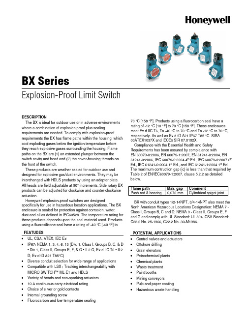
BX SeriesExplosion-Proof Limit SwitchDESCRIPTIONThe BX is ideal for outdoor use or in adverse environments where a combination of explosion proof plus sealing requirements are needed. To comply with explosion-proof requirements the BX has flame paths within the housing, which cool exploding gases below the ignition temperature before they reach explosive gases surrounding the housing. Flame paths on the BX are (1) an extended plunger between the switch cavity and head and (2) the cover-housing threads on the front of the switch.These products are weather sealed for outdoor use and designed for explosive gas/dust environments. They may be interchanged with HDLS products by using an adapter plate. All heads are field adjustable at 90° increments. Side rotary BX products can be adjusted for clockwise and counter-clockwise actuation.Honeywell explosion-proof switches are designed specifically for use in hazardous location applications. The BX enclosure is sealed for protection against corrosion, water, dust and oil as defined in IEC60529. The temperature rating for these products depends upon the seal material used. Products using a fluorosilicone seal have a rating of -40 °C [-40 °F] to 70 °C [158 °F]. Products using a fluorocarbon seal have a rating of -12 °C [10 °F] to 70 °C [158 °F]. These enclosures meet Ex d IIC T6, Ta -40 °C to 70 °C and Ta -12 °C to 70 °C, respectively. As well as Ex d tD A21 IP67 T85 °C. SIRA00ATEX1037X and IECEx SIR 07.0102X.Compliance with the Essential Health and Safety Requirements has been assured by complaiance withEN 60079-0:2006, EN 60079-1:2007, EN 61241-0:2004, EN 61241-0:2006, IEC 60079-0:2004 4th Ed., IEC 60079-0:2007 6th Ed., IEC 61241-0:2004 1st Ed., and IEC 61241-1:2004 1st Ed. The maximum contruction gap (ic) is less than that required by Table 2 of EN/IEC60079-1:2007, clause 5.2.2 as detailed below.Flame path Max. gap CommentPush rod & bearing 0,076 mm Cylindrical spigot jointBX with conduit types 1/2-14NPT, 3/4-14NPT also meet the North American Hazardous Locations Designation: NEMA 7 - Class I, Groups B, C and D; NEMA 9 - Class II, Groups E, F and G and comply with UL Standard: UL 894, CSA Standard: C22.2 No. 25-1966, C22.2 No. 30-M1986.FEATURES•UL, CSA, ATEX, IEC Ex•IP67; NEMA 1, 3, 4, 6, 13 (Div. 1, Class I, Groups B, C, & D • Div 1, Class II, Groups E, F, & G • II 2 G; Ex d IIC T6 • II 2 D; Ex d tD A21 T85°C)•Diverse conduit selection for wide range of applications •Compatible with LSX ; Tracking interchangeability with MICRO SWITCH™ ML-E1 and HDLS•Variety of heads and non-sparking actuators•10 A continuous carry electrical rating•Choice of silver or gold contacts•Internal grounding screw•Fluorocarbon and low-temperature sealingPOTENTIAL APPLICATIONS •Control valves and actuators •Offshore drilling•Grain elevators •Petrochemical plants •Chemical plants•Waste treatment•Paint booths•Mining conveyors•Pulp and paper coating •Hazardous waste handlingBX SeriesSELECTION GUIDEFeatures BX4A3KBX4A3K-1A BX4C3KActuatorLever not included - referencelever required accessory1.5 in fixed length lever with frontmounted nylon roller(.75 in dia. x .25 in wide)N/ATermination Type20 mm conduit 20 mm conduit 20 mm conduitCircuitry1NC 1NO single-pole double-throw, snap-action, double-break1NC 1NO single-pole double-throw, snap-action, double-break1NC 1NO single-pole double-throw, snap-action, double-breakApprovals UL, CSA, ATEX, IEC Ex UL, CSA, ATEX, IEC Ex UL, CSA, ATEX, IEC ExActuator Side rotary Side rotary Top plungerPretravel (P.T.) 15° 15° 1,78 mm [0.070 in]Overtravel (O.T) 60° 60° 4,83 mm [0.190 in]Differential Travel(D.T.)7° 7° 0,51 mm [0.020 in]UL File # - - - CSA File # - - - Operating Position(O.P.) - -58.5 mm ± 0.76 mm[2.305 in ± 0.030 in]Sealing IP67; NEMA 1, 3, 4, 6, 13IP67; NEMA 1, 3, 4, 6, 13I IP67; NEMA 1, 3, 4, 6, 13Product Type Weather-sealed,explosion-proof limit switches/IEC Ex approvalsAmpere Rating10 A (Thermal)Supply Voltage600 Vac and 250 Vdc max.OperatingTemperature Range-40 °C to 70 °C [ -40 °F to 158 °F]Housing Material Zincdie-castHousing Type BX non plug-inSealed Explosion-proof Operating Force (O.F.)0,45 N max. [4 in lb max.]Availability Global Agency Approvals andStandardsUL, CSA, ATEX, IEC Ex; IP67; NEMA 1, 3, 4, 6, 13 (Div. 1, Class I, Groups B, C, & D • Div 1, Class II,Groups E, F, & G • II 2 G; Ex d IIC T6 • II 2 D; Ex d tD A21 T85°C)2 /sensingExplosion-Proof Limit SwitchesSELECTION GUIDEFeatures BX4D3KBXA3KBXA4LActuator N/ALever not included - referencelever required accessoryLever not included - referencelever required accessoryTermination Type20mm conduit 1/2 in - 14NPT conduit 3/4 in - 14NPT conduitCircuitry1NC 1NO single-pole double-throw, snap-action, double-break1NC 1NO single-pole double-throw, snap-action, double-break2NC 2NO single-pole double-throw, snap-Action, double-breakApprovals UL, CSA, ATEX, IEC Ex UL, CSA, ATEX, IEC Ex UL, CSA, ATEX, IEC ExActuator Top roller plunger Side rotary Side rotaryPretravel (P.T.) 1,78 mm [0.070 in] 15° 15°Overtravel (O.T) 4,83 mm [0.190 in] 60° 60°Differential Travel (D.T.) 0,51 mm [0.020 in] 7° 7°UL File# - E61730E61730 CSA File # - LR57327LR57327 Operating Position(O.P.)68.6 mm ± 1 mm[2.700 in ± 0.040 in]- - Sealing IP67; NEMA 1, 3, 4, 6, 13IP67; NEMA 1, 3, 4, 6, 13IP67; NEMA 1, 3, 4, 6, 13Product Type Weather-sealed,explosion-proof limit switches/IEC Ex approvalsAmpere Rating10 A (Thermal)Supply Voltage600 Vac and 250 Vdc max.Operating TemperatureRange-40 °C to 70 °C [ -40 °F to 158 °F]Housing Material Zincdie-castHousing Type BXnon-plug-in Sealed Explosion-proof Operating Force (O.F.)0,45 N max. [4 in lb max.]Availability Global Agency Approvals andStandardsUL, CSA, ATEX, IEC Ex; IP67; NEMA 1, 3, 4, 6, 13 (Div. 1, Class I, Groups B, C, & D • Div 1,Class II, Groups E, F, & G • II 2 G; Ex d IIC T6 • II 2 D; Ex d tD A21 T85°C)Honeywell • Sensing and Control 3BX SeriesMOUNTING DIMENSIONS (For reference only) mm/inFig. 1Conduit sizes 1/2-14NPT, 3/4-14NPT, M20, PG13.5, PF1/2 are available for each switch type.Verify that the mating threaded fitting is identical with the conduit thread shown on the product nameplate 4 /sensingExplosion-Proof Limit SwitchesHoneywell • Sensing and Control 5 LEVERS – REQUIRED ACCESSORIESLSZ51A LSZ51C LSZ52C LSZ52J LSZ52K Lever style Roller – standard Roller – standard Roller – adjustable Roller – adjustable Roller – adjustable Comment Roller - standard;material: nylon;roller mounted onfront of leverRoller - standard;material: nylon;roller mounted onback of leverRoller - adjustable;material: nylon;roller mounted onfront of leverRoller - adjustable;material: nylon;roller mounted onfront of leverRoller - adjustable;material: nylon;roller mounted onfront of lever Radius 38,1 mm[1.5 in]38,1 mm[1.5 in]38,1 mm to 88,9 mm[1.5 in to 3.5 in]38,1 mm to 88,9 mm[1.5 in to 3.5 in]38,1 mm to 88,9 mm[1.5 in to 3.5 in] Diameter 19,05 mm[0.75 in]19,05 mm[0.75 in]19,05 mm[0.75 in]25,4 mm[1.0 in]38,1 mm[1.5 in] Width 6,35 mm[0.25 in]6,35 mm[0.25 in]6,35 mm[0.25 in]12,7 mm[0.5 in]6,35 mm[0.25 in] Product type LeverAvailability GlobalLSZ53E LSZ53S LSZ54MLSZ55A LSZ55C Lever style Roller – yoke Roller – yoke Rod – standard Roller with offset Roller with offset Comment Roller - yoke;material: nylon;roller mounted onback-front of leverRoller - yoke;material: nylon;roller mounted onback-back of leverRod - standard;material: aluminum;material: aluminumRoller - with offset;material: nylon;roller mounted onback of leverRoller - with offset;material: nylon;roller mounted onfront of lever Radius 38,1 mm[1.5 in]38,1 mm[1.5 in]139,7 mm[5.5 in]38,1 mm[1.5 in]38,1 mm[1.5 in] Diameter 19,05 mm[0.75 in]19,05 mm[0.75 in]- 19,05mm[0.75 in]19,05 mm[0.75 in] Width 6,35 mm[0.25 in]6,35 mm[0.25 in]- 6,35mm[0.25 in]6,35 mm[0.25 in] Product type LeverAvailability GlobalWARNINGPERSONAL INJURYDO NOT USE these products as safety or emergency stop devices or in any other application where failure of the product could result in personal injury.Failure to comply with these instructions could result in death or serious injury.WARNINGOPENING PRODUCTS HAZARDDO NOT OPEN these products when energized or in a flammable gas atmosphere.Failure to comply with these instructions could result in death or serious injury.WARRANTY/REMEDYHoneywell warrants goods of its manufacture as being free of defective materials and faulty workmanship. Honeywell’s standard product warranty applies unless agreed to otherwise by Honeywell in writing; please refer to your order acknowledgement or consult your local sales office for specific warranty details. If warranted goods are returned to Honeywell during the period of coverage, Honeywell will repair or replace, at its option, without charge those items it finds defective.The foregoing is buyer’s sole remedy and is in lieu of all other warranties, expressed or implied, including those of merchantability and fitness for a particular purpose. In no event shall Honeywell be liable for consequential, special, or indirect damages.While we provide application assistance personally, through our literature and the Honeywell web site, it is up to the customer to determine the suitability of the product in the application.Specifications may change without notice. The information we supply is believed to be accurate and reliable as of this printing. However, we assume no responsibility for its use.WARNINGIMPROPER CONDUIT THREAD USEDO NOT USE any other conduit thread than the one identified on the product. Verify that the mating threaded fitting is identical with the conduit thread shown on the product nameplate.Failure to comply with these instructions could result in death or serious injury.WARNINGMISUSE OF DOCUMENTATION•The information presented in this product sheet is for reference only. Do not use this document as a productinstallation guide.•Complete installation, operation, and maintenance information is provided in the instructions supplied witheach product.Failure to comply with these instructions could result in death or serious injury.SALES AND SERVICEHoneywell serves its customers through a worldwide network of sales offices, representatives and distributors. For application assistance, current specifications, pricing or name of the nearest Authorized Distributor, contact your local sales office or:E-mail:*********************Internet: /sensingPhone and Fax:Asia Pacific +65 6355-2828+656445-3033FaxEurope +44 (0) 1698 481481+44 (0) 1698 481676 FaxLatin America +1-305-805-8188+1-305-883-8257FaxUSA/Canada +1-800-537-6945+1-815-235-6847+1-815-235-6545FaxSensing and Control Honeywell1985 Douglas Drive NorthGolden Valley, MN 55422 /sensing 002306-3-EN IL50 GLO Printed in USAJuly 2008Copyright © 2008 Honeywell International Inc. All rights reserved.。