RUR-D1615中文资料
核电站设备主要金属材料

1.核岛用金属材料概述不同堆型,其结构和用途虽有所不同,但在实现核裂变反应和可控制的过程是相同的,都需要燃料元件、堆内构件、控制棒、反射层、冷却剂和慢化剂(快堆除外)以及包容他们的压力容器或压力管道等,因而需要各种各样的材料来制作相关部件,以实现核能向热能、热能向电能的安全、高效率的转化。
按照相关设备部件服役工况或使用功能的不同,核电设备可分为核一级、核二级、核三级和非核级。
有核级要求的设备,一般即称其所用材料为核电关键材料。
核电常用的关键材料大体可分为碳钢、不锈钢和特殊合金;若进一步细分,则有碳(锰)钢、低合金钢、不锈钢、锆合金、钛铝合金和镍基合金等,按品种则有铸锻件、板、管、圆钢、焊材等等。
核反应堆的发展,从一开始就包括了材料的开发与优化,材料的发展决定了其发展情况。
因为核电具有新的热传导条件及特殊的环境条件,如辐照或冷却剂腐蚀等,要求所用材料必须能适合于这些应用条件;强调材料的另一个原因,是核电站系统比常规电站有更高的安全要求。
由于我国目前主要是建造第二代成熟的1000MW压水堆核电站、通过技术引进并吸收国外先进技术以发展先进的第三代1000MW级压水堆核电站。
因此,本讲义以压水堆核电站为例,对其不同设备的用材做一简单介绍。
在压水堆核岛中,主要设备除反应堆及压力容器外,还有蒸汽发生器、冷却剂主泵机组、稳压器及主管道等。
由于这些部件在核岛内的位置、作用和工况不同,故材料的使用要求和环境条件也不尽相同,不同程度地存在辐照或酸腐蚀等;不仅要考虑常规的一些要求(如强度、韧性、焊接性能和冷热加工性能),而且须考虑辐照带来的组织、性能、尺寸等变化,如晶间腐蚀,应力腐蚀和低应力脆断、以及材料间的相容性、与介质的相容性,以及经济可行性等。
为便于从它们的服役特点中理解每个部件的功能、选择依据,下面将压水反应堆核岛内重要金属部件的工况、要求以及他们的所用材料体系简述如下。
1.1压水堆零/部件用金属材料1.1.1包壳材料包壳,是指装载燃料芯体的密封外壳。
第12章 12CM15型连续采煤机
第12章 12CM15型连续采煤机12.1 概述美国久益(JOY)公司生产的12CM15型连续采煤机,是一种具有完全遥控功能的高产量连续采煤机,适用于中厚煤层。
该机截割滚筒直径为1120mm(44in),截割宽度为3300mm (130in),最大截割高度为3685mm(145in),有一台宽760mm(30in)、运行速度为2.41m/s (475fpm)配有离心式装载拨盘的输送机。
12CM15型连续采煤机有2台170kW(228马力)带限矩器保护的交流电动机提供动力,这2台电动机与截割臂中心线平行安装。
每台截割电动机均通过内置扭矩轴同齿轮箱的齿轮相接。
还有2台45kW(60马力)的装运电动机,2台37kW(50马力)的行走电动机,1台40kW(54马力)油泵电动机,1台19kW(25马力)集尘风机电动机。
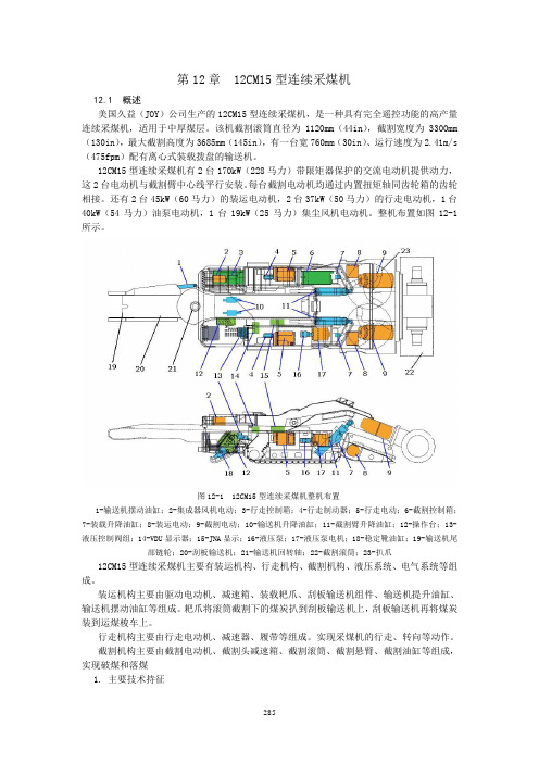
整机布置如图12-1所示。
图12-1 12CM15型连续采煤机整机布置1-输送机摆动油缸;2-集成器风机电动;3-行走控制箱;4-行走制动器;5-行走电动;6-截割控制箱;7-装载升降油缸;8-装运电动;9-截割电动;10-输送机升降油缸;11-截割臂升降油缸;12-操作台;13-液压控制阀组;14-VDU显示器;15-JNA显示;16-液压泵;17-液压泵电机;18-稳定靴油缸;19-输送机尾部链轮;20-刮板输送机;21-输送机回转轴;22-截割滚筒;23-扒爪12CM15型连续采煤机主要有装运机构、行走机构、截割机构、液压系统、电气系统等组成。
装运机构主要由驱动电动机、减速箱、装载耙爪、刮板输送机组件、输送机提升油缸、输送机摆动油缸等组成。
耙爪将滚筒截割下的煤炭扒到刮板输送机上,刮板输送机再将煤炭装到运煤梭车上。
行走机构主要由行走电动机、减速器、履带等组成。
实现采煤机的行走、转向等动作。
截割机构主要由截割电动机、截割头减速箱、截割滚筒、截割悬臂、截割油缸等组成,实现破煤和落煤1. 主要技术持征12CM15型连续采煤机电动机技术持征见表12-1。
MAX1615中文资料
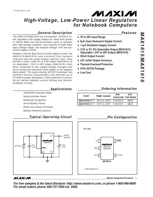
(VIN = 15V, SHDN = VIN, ILOAD = 5µA, TA = TMIN to TMAX, unless otherwise noted. Typical values are at TA = +25°C.) (Note 2) PARAMETER Input Voltage Range Supply Current Minimum Load Current Shutdown Supply Current Dropout Supply Current IIN SHDN = GND (shutdown mode) Output set to 5V, VIN = 4V ILOAD = 1mA, TA = +25°C, VIN = 6V to 28V ILOAD = 5µA to 30mA, TA = TMIN to TMAX, VIN = 6V to 28V FB = OUT, VIN = 6V to 28V VFB = 1.3V ILOAD = 30mA (Note 4) VIN = 6V IN = unconnected, VOUT forced to 5V MAX1615 MAX1616 Rising edge of IN or SHDN to OUT within specification limits, RL = 500Ω, COUT = 6.8µF, VOUT set to 5V VOSH RL = 500Ω, COUT = 10µF within 90% of nominal output voltage 0.5 0.16 0.23 1 100 70 TA = +25°C TMIN = TMIN to TMAX TA = +25°C 5/3 = GND 5/3 = OUT 5/3 = GND 5/3 = OUT TA = +25°C, ILOAD = 1mA TA = TMIN to TMAX, ILOAD = 5µA to 30mA 3.26 4.95 3.15 4.75 1.215 1.18 -10 12 1.240 70 3.33 5.05 3.40 5.15 V 3.48 5.25 1.265 1.28 30 350 V V nA mV mA µA µF/mA SYMBOL VIN IIN SHDN = IN, TA = +25°C SHDN = IN, VIN = 6V to 28V, TA = TMIN to TMAX CONDITIONS MIN 4 6.2 TYP MAX 28 8 15 5 1.5 3 UNITS V µA µA µA µA
D202RU资料

Key Features:• 2W Output Power• 4:1 Input Voltage Range • 1,000 VDC Isolation • Short Circuit Protected • Miniature SIP Case • Single & Dual Outputs • 1.0 MH MTBF• Industry Standard Pin-OutD200RU Miniature SIP , 2W Ultra-Wide 4:1 Input DC/DC Con v ert e rsSeriesInputParameterConditions Min.Typ.Max.Units Input Start Voltage24 VDC Input 4.5 6.08.5VDC 48 VDC Input 8.512.017.0Input FilterCapacitor FilterReverse Polarity Input Current 0.5A Short Circuit Input Power1,500mW OutputParameterConditionsMin.Typ.Max.Units Output Voltage Accuracy ±1.0±2.0%Output Voltage Balance ±1.0±2.0%Line Regulation Vin = Min to Max ±0.3±0.5%Load RegulationIout = 25% to 100%±0.5±0.75%Ripple & Noise (20 MHz) (Note 1)3050mV P - P Ripple & Noise (20 MHz)Over Line, Load & Temp.75mV P - P Ripple & Noise (20 MHz)15mV rms Output Power Protection120%Transient Response Time (Note 2)25% Load Step Change100300μSec Transient Response Deviation ±3.0±5.0%Temperature Coeffi cient ±0.01±0.02%/°COutput Short CircuitContinuousGeneralParameterConditionsMin.Typ.Max.Units Isolation Voltage60 Seconds1,000VDC Isolation Test Voltage Flash Tested For 1 Sec1,100VDC Isolation Resistance 500 VDC 1,000M ΩIsolation Capacitance 100 kHz, 1V250500pF Switching Frequency300kHz EnvironmentalParameterConditionsMin.Typ.Max.Units Operating Temperature Range Ambient -40+25+65°C Operating Temperature Range Case -40+25+65°C Storage Temperature Range -55+105°C Cooling Free Air ConvectionHumidityRH, Non-condensing95%PhysicalCase Size1.02 x 0.36 x 0.49 Inches (25.95 x 9.25 x 12.45 mm)Case Material Non-Conductive Black Plastic (UL94-V0)Weight0.23 Oz (6.5g)Reliability Specifi cationsParameter ConditionsMin.Typ.Max.Units MTBFMIL HDBK 217F , 25°C, Gnd Benign1,000kHours Absolute Maximum RatingsParameterConditionsMin.Typ.Max.Units Input Voltage Surge (1 Sec)24 VDC Input -0.750.0VDC 48 VDC Input-0.7100.0Lead Temperature1.5 mm From Case For 10 Sec260°C Internal Power DissipationAll Models2,500mWCaution: Exceeding Absolute Maximum Ratings may damage the module. These are not continuous operating ratings.Electrical Specifi cationsSpecifi cations typical @ +25°C, nominal input voltage & rated output current, unless otherwise noted. Specifi cations subject to change without notice.MicroPower Direct292 Page Street Suite DStoughton, MA 02072USAT: (781) 344-8226F: (781) 344-8481E: sales@ W: RoHS CompliantModel Selection GuideMechanical DimensionsMechanical Notes:• All dimensions are typical in inch e s (mm)• Tolerance x.xx = ±0.01 (±0.25)Notes:1. When measuring output ripple, it is recommended that an external 0.47 μF ceramic capacitor be placed from the +Vout pin to the -Vout pin for single output units and from each output to common for dual output units. For noise sensitive applications, the use of 3.3 μF capacitors will reduce the output ripple.2. T ransient recovery is measured to within a 1% error band for a load step change of 75% to 100%.3. O peration at no-load will not damage these units. However, they may not meet all specifi cations.4. Dual output units may be connected to provide a 10 VDC, 24 VDC, or 30 VDC output. To do this, connect the load across the positive (+Vout) and negative (-Vout) outputs and fl oat the output com-mon.5. The converter should be connected to a low ac-impedance source. An input source with a highly inductive impedance may affect the stability of the converter. In applications where the converter output loading is high and input power is supplied over long lines, it may be necessary to use a capacitor on the input to insure start-up.In this case, it is recommended that a low ESR (ESR <1.0Ω at 100 kHz) capacitor be mounted close to the converter. For all models, it is recommended a 1.5 μF be used. 6. The optional remoteon/off control pinis referenced tothe -Vin pin. The standby inputcurrent is typically 0.1 mA (0.2 mamaximum).7. It is recommended that a fuse be used on the input of a power sup-ply for protection. See the table above for the correct rating.Model Number InputOutput Refl ectedRipple Current (mA)Effi ciency(%, Typ)Fuse RatingSlow-Blow (mA)Voltage (VDC)Current (mA)Voltage (VDC)Current (mA, Max)Current(mA, Min)Nominal Range Full-Load No-Load D201RU 249.0 - 36.09720 3.3500.0125.030071350D202RU 249.0 - 36.011020 5.0400.0100.030076350D203RU 249.0 - 36.01062012.0167.042.030079350D204RU 249.0 - 36.01052015.0134.033.030080350D205RU 249.0 - 36.011420±5.0±200.0±50.030073350D206RU 249.0 - 36.010820±12.0±83.0±21.030077350D207RU 249.0 - 36.010620±15.0±67.0±17.030079350D211RU 4818.0 - 75.04915 3.3500.0125.060070135D212RU 4818.0 - 75.05815 5.0400.0100.060072135D213RU 4818.0 - 75.0541512.0167.042.060078135D214RU 4818.0 - 75.0541515.0134.033.060078135D215RU 4818.0 - 75.06015±5.0±200.0±50.060070135D216RU 4818.0 - 75.05515±12.0±83.0±21.060076135D217RU4818.0 - 75.05515±15.0±67.0±17.060076135Pin SingleDual1-Vin -Vin 2+Vin +Vin 3Remote ON/OFF 6+Vout +Vout 7NC Common 8NC NC 9-Vout -VoutNF = No ConnectionPin ConnectionsOutput (VDC)μF Max 3.32,2005.01,00012.017015.0110±5.0470±12.0100±15.047Note: For dual outputunits, Cap load is given for each output.Capacitive LoadMin Max On <0.6 VDC to Open Circuit Off 2.7 VDC 15.0 VDC In. Current (on)-1 mA In. Current (off)1 mA Derating CurveMicroPower Direct292 Page Street Ste D Stoughton, MA 02072 • TEL: (781) 344-8226 • FAX: (781) 344-8481 • E-Mail: sales@。
LT1615

采用SOT-23封装的微功率升压型DC/DC转换器LT1615/LT1615-1- 1 -采用SOT-23封装的微功率升压型DC/DC转换器 LT1615/1615-1一、 概述及特点LT1615/LT1615-1是采用5引脚SOT-23封装的微功率DC/DC转换器。
LT1615是专为具有350mA电流限制和1.2V至15V输人电压范围的较高功率系统而设计;而LT1615-1则专为具有100mA 电流限制和1V至15V扩展输入电压范围的较低功率和单节电池应用,否则,两款器件都具有相同的功能。
在没有负载时,两个器件的静态电流均仅为20uA,在停机时则进一步减少到0.5uA。
电流限制、固定关闭时间控制方案保存工作电流,使得器件在很宽的负载电流范围内具有很高的效率。
由于具有36V开关,利用简单的升压拓扑结构就能轻而易举地产生高达34V 的高电压输出,而无需采用昂贵的变压器。
LT1615的400 ns低关闭时间允许用户采用微型电感和电容器,从而在对空间敏感的便携式应用中,将器件的电路板占位面积和系统成本降至最小。
特点:● 低静态电流:在正常工作方式时为20uA;在停机模式时小于1uA● V IN低至1V时仍可以工作● 低V CESAT电压开关:在300mA时为250mV● 5引脚(Thin)SOT-23封装● 采用小型表面贴装元件● 高输出电压:高达34V应用领域:● LCD偏置● 手持电脑● 后备电池● 数码相机采用SOT-23封装的微功率升压型DC/DC转换器LT1615/1615-1 - 3 -三、绝对最大额定值参数 额定值 单位V IN,/SHDN 电压 15 VSW 电压 36 VFB 电压 V IN V流进FB引脚的电流 1 mA结温 125 ℃工作温度范围 -40~85 ℃贮存温度范围 -65~150 ℃焊接温度 300(10秒钟) ℃四、电特性(●代表技术指标适合整个工作温度范围,否则指标是在T A=25℃,V IN=1.2V,V/SHDN=1.2V,除非另外注明。
2SD1615中文资料
Document No. D10198EJ3V0DSD0 (3rd edition) (Previous No. TC-5810A)Date Published June 1995 P Printed in Japan ©198522SD1615, 2SD1615ATYPICAL CHARACTERISTICS (T A = 25 ˚C)T A – Ambient Temperature – ˚C4080120160200P T – T o t a l P o w e r D i s s i p a ti o n – WTOTAL POWER DISSIPATION vs.AMBIENT TEMPERATURECOLLECTOR CURRENT vs.BASE TO EMITTER VOLTAGEV CE – Collector to Emitter Voltage – VI C – C o l l e c t o r C u r r e n t – m AI C – Collector Current – ADC CURRENT GAIN vs.COLLECTOR CURRENTh E F – D C C u r r e n t G a i nCOLLECTOR CURRENT vs.COLLECTOR TO EMITTER VOLTAGEV CE(sat) – Collector Saturation Voltage – V I C – C o l l e c t o r C u r r e n t – A0.010.020.050.10.20.512510I C – Collector Current – ACOLLECTOR AND BASE SATURATION VOLTAGE vs. COLLECTOR CURRENTV C E (s a t ) – C o ll e c t o r S a t u r a t i o n V o l t a g e – V V B E (s a t ) – B a s e S a t u r a t i o n V o l t a g e – VSAFE OPERATING AREA(TRANSIENT THERMAL RESISTANCE METHOD)5210.50.20.10.050.020.01125102050100V CE – Collector to Emitter Voltage – V I C – C o l l e c t o r C u r r e n t – A3GAIN BANDWIDTH PRODUCT vs.EMITTER CURRENTf T – G a i n B a n d w i d t h P r o d u c t – M H ZI C– Collector Current – AOUTPUT CAPCITANCE vs.COLLECTOR TO BASE VOLTAGEC o b – O u t p u t C a p a c i t a n c e – p FV CB – Collector to Base Voltage – VI C – Collector Current – ASWITCHING TIME vs.COLLECTOR CURRENTt – S w i t c h i n g T i m e– sµREFERENCE[MEMO]No part of this document may be copied or reproduced in any form or by any means without the prior written consent of NEC Corporation. NEC Corporation assumes no responsibility for any errors which may appear in this document.NEC Corporation does not assume any liability for infringement of patents, copyrights or other intellectual property rights of third parties by or arising from use of a device described herein or any other liability arising from use of such device. No license, either express, implied or otherwise, is granted under any patents, copyrights or other intellectual property rights of NEC Corporation or others.While NEC Corporation has been making continuous effort to enhance the reliability of its semiconductor devices, the possibility of defects cannot be eliminated entirely. To minimize risks of damage or injury to persons or property arising from a defect in an NEC semiconductor device, customer must incorporate sufficient safety measures in its design, such as redundancy, fire-containment, and anti-failure features.NEC devices are classified into the following three quality grades:“Standard“, “Special“, and “Specific“. The Specific quality grade applies only to devices developed based ona customer designated “quality assurance program“ for a specific application. The recommended applicationsof a device depend on its quality grade, as indicated below. Customers must check the quality grade of each device before using it in a particular application.Standard:Computers, office equipment, communications equipment, test and measurement equipment, audio and visual equipment, home electronic appliances, machine tools, personal electronicequipment and industrial robotsSpecial:Transportation equipment (automobiles, trains, ships, etc.), traffic control systems, anti-disaster systems, anti-crime systems, safety equipment and medical equipment (not specifically designedfor life support)Specific:Aircrafts, aerospace equipment, submersible repeaters, nuclear reactor control systems, life support systems or medical equipment for life support, etc.The quality grade of NEC devices in “Standard“ unless otherwise specified in NEC's Data Sheets or Data Books.If customers intend to use NEC devices for applications other than those specified for Standard quality grade, they should contact NEC Sales Representative in advance.Anti-radioactive design is not implemented in this product.M4 94.11。
EBR15H中文资料(adam tech)中文数据手册「EasyDatasheet - 矽搜」

EBQ-04--c
.073 [1.85]
.472 [12.00]
.157 [4.00]
'Y' X No of POLES
.275 [7.00]
'Y'
REPLACE 'Y' WITH PITCH A = .138 [3.50] B = .150 [3.81] E = .276 [7.00] G = .300 [7.62]
EB108 = 0.342“直 EB109 = 0.850“直
中心线 间距
A = .138" [3.50mm] B = .150" [3.81mm] c = .197" [5.00mm] D = .200" [5.08mm] E = .276" [7.00mm] G = .300" [7.62mm] H = .394" [10.00mm] J = .400" [10.16mm] k = .591" [15.00mm] S = .374" [9.50mm]
.100 [2.54] .200 [5.08]
.138 [3.50]
.038 [0.95]
.020 [0.50]
.600 [15.24]
.020 [0.50]
.997 [25.30]
.543 [13.80]
EBv2-02-D
.193 [4.90]
.031 [0.80]
.600 [15.24]
3位置堆放块
电气:
Operating voltage: 250V AC max. Current rating: 7 to 15 Amp max 接触电阻:20mΩ以下.初始 绝缘电阻:5000MΩ分钟. Dielectric withstanding voltage: 1500V AC for 1 minute
EN12165-1998 CH中文版
EN12165-1998 CH中文版欧洲标准 EN12165-1998 CH铜及铜合金化学成分及未加工锻坯BS EN 12165:19981 范围此欧洲标准规定了直管圆形铜棒及铜合金的成分要求、特性要求及尺寸公差,尤其用于铸造中的。
该标准同样也适用于规则多变形的铜棒,空心棒、矩形棒及用于锻造的剖面。
样品程序,即查证是否符合本标准要求的测试方法,且规定了交货条件。
This European Standard specifies the composition,property requirements and dimensionaltolerances for copper and copper alloy round rod supplied instraight lengths, specifically intended for forging. This standard is also applicable to regular polygonal rod, hollow rod, rectangular bar and profiles intended for forging. The sampling procedures, the methods of testfor verification of conformity to the requirements of this standard, and the delivery conditions are also specified.2 参考标准(略)EN 1655, Copper and copper alloys, Declarations of conformity.prEN 1976, Copper and copper alloys,Cast unwrought copper products.EN 10003-1, Metallic materials,Brinell hardness test, Part 1: Test method.EN 10204, Metallic products, Types of inspection documents.EN ISO 6509:1995, Corrosion of metals and alloys,Determination of dezincification resistance of brass.(ISO 6509:1981)ISO 1811-2, Copper and copper alloys, Selection and preparation of samples for chemical analysis,Part 2: Sampling of wrought products and castings. ISO 6507-1, Metallic materials, Hardness test,Vickers test, Part 1: HV 5 to HV 100. NOTE Informative references to documents used in the preparation of this standard, and cited at the appropriate places in the text, are listed in a bibliography; see annex A. 3 定义因标准需要,提供下述定义:For the purposes of this standard, the following definitions apply:3.1 锻造金属坯料经锤打或挤压产生变形而获得锻件,包括平面之间的锤打。