48IKS6-0505-9K中文资料
LGK说明书
LGK系列逆变式空气等离子切割机属于一种全新设计的金属加工设备,采用了二十世纪末先进的绝缘栅大功率晶体管IGBT及脉冲宽度调制(PWM)软开关技术设计制造。
该系列切割机可以切割所有金属材料,特别适合于切割火焰切割法不能切割的高合金钢和有色金属。
该系列切割机具有理想的静外特性及良好的动态特性,具备高频引弧功能,特点如下: 电弧能量高度集中,稳定性好,切割力强。
切割速度快(是气割的3 – 5倍)。
切割成本低。
切口狭窄,光洁,整齐,接近于垂直。
工件变形小。
切割电流连续可调。
引弧容易。
操作非常方便。
重量轻,体积小,便于移动。
高效率,高功率因数,是一种高效节能设备。
噪音低,适应性强。
具有自锁,非自锁两种功能,适应长短割缝的不同要求,能减少工人的劳动强度。
便于组成自动切割设备。
该系列空气等离子切割机的制造符合标准GB15579.1-2004《弧焊设备第一部分:焊接电源》。
●请务必遵守本说明书规定的注意事项,否则可能发生事故。
●输入电源的设计施工、安装场地的选择、高压气体的使用等,请按照相关标准和规定进行。
●无关人员请勿进入切割作业场所内。
●请有专业资格的人员对切割机进行安装、检修、保养及使用。
●不得将本切割机用于切割以外的用途(如充电、加热、管道解冻等等)。
●如果地面不平,要注意防止切割机倾倒。
●切割机通电时,严禁接触气电接头及切割枪裸露的金属部分。
●请专业电气人员用规定截面的铜导线将焊机接地。
●请专业电气人员用规定截面的铜导线将切割机接入电源,绝缘护套不得破损。
●在潮湿、活动受限处作业时,要确保身体与母材之间的绝缘。
●高空作业时,请使用安全网。
●不用时,请关闭输入电源。
●请使用规定的排风设备,避免发生气体中毒和窒息等事故。
●在容器底部作业时,有害气体会沉积在周围,造成窒息。
应特别注意通风。
●请佩戴足够遮光度的保护眼镜。
弧光会引起眼部发炎。
●请使用切割用皮质保护手套、长袖衣服、帽子、护脚、围裙等保护用品,以免弧光、飞溅及铁渣灼伤、烫伤皮肤。
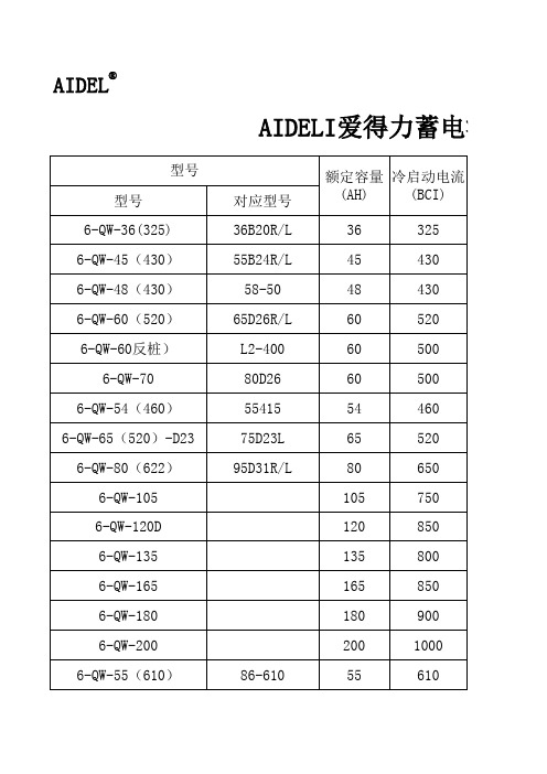
爱得力蓄电池规格对照表
6-QW-60(600)-G78 20-72MF 90-500 57117 34-550 54017 58043 20-100MF
78-6000 88
600 610 500 525 500 360 680 750
蓄电池价格表
牌价 195 231 245 285 272 310 302 285 360 436 520 550 610 710 755 275 凯越、乐骋、景程等 卡车 桑塔纳、红旗、捷达等 奥德赛、普利马、远舰、哈飞赛马等 长城、中兴、万丰、一汽丰田等 东风 适用车型 奥括、昌河、比亚迪、松花江等 昌河、佳宝、夏利、威驰、哈飞等 五菱之光、切诺基等 万丰、猎豹、金杯本田、丰田等 富康、POLO、宝来、帕萨特等
342 354 262 319 336 246 427 460
别克君威 奥迪、蒙迪欧、江铃金顺、沃尔沃等 赛欧 蒙迪欧致胜 君越 比亚迪F0 奥迪 宝马、奔驰、沃尔沃等 德国大众爱得力国际控股有限公司 2017年11月6日起实行
AIDEL®
AIDELI爱得力蓄电池价格表
型号 型号 6-QW-36(325) 6-QW-45(430) 6-QW-48(430) 6-QW-60(520) 6-QW-60反桩) 6-QW-70 6-QW-54(460) 6-QW-65(520)-D23 6-QW-80(622) 6-QW-105 6-QW-120D 6-QW-135 6-QW-165 6-QW-180 6-QW-200 6-QW-55(610) 86-610 对应型号 36B20R/L 55B24R/L 58-50 65D26R/L L2-400 80D26 55415 75D23L 95D31R/L 额定容量 冷启动电流 (AH) (BCI) 36 45 48 60 60 60 54 65 80 105 120 135 165 180 200 55 325 430 430 520 500 500 460 520 650 750 850 800 850 900 1000 610
48芯及12芯ADSS光缆参数

敷设
-10~+60
运输和运行
-40~+70
创作时间:贰零贰壹年柒月贰叁拾日
KN/mm2
10.46
热膨胀系数
10-6/℃
6.96
抗压强度
N/100mm
长期
1000
短期
2200
最小弯曲半径
mm
运行
125
敷设
250
适应温度范围
℃
敷设
-10~+60
运输和运行
-40~+70
ADSS-12B1-AT-200 技术性能参数表
1.外护套
2.芳纶纱加强层
3.内护套
4.套管
5.光纤
6.阻水油膏
16.25
最大使用张力(MAT)
KN
40%RTS
6.50
年平均运行张力(EDS)
KN
20%RTS
3.25
极限运行张力(UOS)
KN
60%RTS
9.75
杨氏模量
KN/mm2
13.96
热膨胀系数
10-6/℃
2.35
抗压强度
N/100mm
长期
1000
短期
2200
最小弯曲半径
mm
运行
110
敷设
220
适应温度范围
ADSS-48B1-AT-100 技术性能参数表之邯郸勺丸创作
创作时间:贰零贰壹年柒月贰叁拾日
1.外护套
2.芳纶纱加强层
3.内护套
4.套管
5.光纤
6.阻水油膏
7.纤油膏
8.非金属加强件
项 目
单 位
特殊要求
包管值
MNS技术规格书
一、工程概述本技术规格书用于青岛市城市粪便无害化采购电器设备中的400V低压开关柜(抽出式)。
它对400V低压开关柜的制造、安装、试验、供货的相关工作提出了最低要求。
青岛市城市粪便无害化采购电器设备项目400V低压开关柜采用MNS型,共4面。
二、标准和规范本设备的制造、试验和验收除了满足本技术规格书的要求外,还符合如下标准:GB1207-86 《电压互感器》GB1208-87 《电流互感器》GB3983.1-89 《低电压并联电容器》GB4942.4-93 《低压电器外壳防护等级》GB7251.1-1997 《低压成套开关设备》GB7261-87 《继电器及继电保护装置基本试验方法》GB9166-88 《低压成套开并设备基本试验方法》GB13539-92 《低压熔断器》GB/T14048.1-93 《低压开关设备和控制设备》IEC129 《交流断路器和接地保护》IEC185 《电流互感器》IEC186 《电压互感器》IEC269 《低压熔断器》IEC439-1.1992 《低压成套开关设备和控制设备》IEC446 《绝缘和非绝缘导体的色标》IEC73 《指示灯和按钮的色标》IEC947 《低压开关设备控制设备》IEC60439 《定型试验和部分经定型试验的组合装置》上述标准所包含的条文,通过在本技术规范中引用而构成为本技术规范的条文。
本技术规范出版时,所列标准版本均为有效。
所有标准都会被修订,供需双方应探讨使用上述标准最新版本的可能性。
标准之间有矛盾时,按技术要求较高的标准执行。
三、供货内容1、设备名称:400V低压开关柜(抽出式)11)操作:电动/手动,弹簧储能,储能电机工作电压AC220V,工作范围85%~110%。
电动机构分合闸线圈的电压为AC 220V,工作范围合闸线圈85%~110%,分闸线圈 70%~110%。
12)电子式脱扣保护器:采用三段保护2、塑壳断路器1)品牌系列:ABB T系列2)额定工作电流:250A、160A、32-100A3)额定工作电压:AC400v 三相4)额定绝缘电压:800v5)额定频率:50Hz6)极限短路容量:Icu=36kA7)额定分断容量:Ics=36kA8)极数:三极9)脱扣单元:TMD、TMA3、多功能指示仪表1)显示:晶体管2)品牌系列:珠海派诺 PMAC625-Z3)额定电压:400V4)额定频率:50HZ5)测量范围:三相电流、电压、有功功率、无功功率、功率因数等4、电流互感器1)型式:塑料外壳式2)品牌型号:浙江泰成 LMZ-0.663)电流比:1200/5、500/5、30~300/55、电容柜电容柜元器件全部选用ABB品牌,配套使用七、技术要求1、开关柜柜体采用 2.0mm厚冷轧钢板闸板,柜体静电喷塑,颜色为计算机灰色(RAL7035)。
max485esa中文资料
General DescriptionThe MAX481, MAX483, MAX485, MAX487–MAX491, andMAX1487 are low-power transceivers for RS-485 and RS-422 communication. Each part contains one driver and onereceiver. The MAX483, MAX487, MAX488, and MAX489feature reduced slew-rate drivers that minimize E MI andreduce reflections caused by improperly terminated cables,thus allowing error-free data transmission up to 250kbps.The driver slew rates of the MAX481, MAX485, MAX490,MAX491, and MAX1487 are not limited, allowing them totransmit up to 2.5Mbps.These transceivers draw between 120µA and 500µA ofsupply current when unloaded or fully loaded with disableddrivers. Additionally, the MAX481, MAX483, and MAX487have a low-current shutdown mode in which they consumeonly 0.1µA. All parts operate from a single 5V supply.Drivers are short-circuit current limited and are protectedagainst excessive power dissipation by thermal shutdowncircuitry that places the driver outputs into a high-imped-ance state. The receiver input has a fail-safe feature thatguarantees a logic-high output if the input is open circuit.The MAX487 and MAX1487 feature quarter-unit-loadreceiver input impedance, allowing up to 128 MAX487/MAX1487 transceivers on the bus. Full-duplex communi-cations are obtained using the MAX488–MAX491, whilethe MAX481, MAX483, MAX485, MAX487, and MAX1487are designed for half-duplex applications.________________________Applications Low-Power RS-485 Transceivers Low-Power RS-422 Transceivers Level Translators Transceivers for EMI-Sensitive Applications Industrial-Control Local Area Networks__Next Generation Device Features o For Fault-Tolerant Applications MAX3430: ±80V Fault-Protected, Fail-Safe, 1/4Unit Load, +3.3V, RS-485 Transceiver MAX3440E–MAX3444E: ±15kV ESD-Protected,±60V Fault-Protected, 10Mbps, Fail-Safe, RS-485/J1708 Transceivers o For Space-Constrained Applications MAX3460–MAX3464: +5V, Fail-Safe, 20Mbps,Profibus RS-485/RS-422 Transceivers MAX3362: +3.3V, High-Speed, RS-485/RS-422Transceiver in a SOT23 Package MAX3280E–MAX3284E: ±15kV ESD-Protected,52Mbps, +3V to +5.5V, SOT23, RS-485/RS-422,True Fail-Safe Receivers MAX3293/MAX3294/MAX3295: 20Mbps, +3.3V,SOT23, RS-485/RS-422 Transmitters o For Multiple Transceiver Applications MAX3030E–MAX3033E: ±15kV ESD-Protected,+3.3V, Quad RS-422 Transmitters o For Fail-Safe Applications MAX3080–MAX3089: Fail-Safe, High-Speed (10Mbps), Slew-Rate-Limited RS-485/RS-422Transceiverso For Low-Voltage ApplicationsMAX3483E/MAX3485E/MAX3486E/MAX3488E/MAX3490E/MAX3491E: +3.3V Powered, ±15kVESD-Protected, 12Mbps, Slew-Rate-Limited,True RS-485/RS-422 Transceivers For pricing, delivery, and ordering information, please contact Maxim Direct at1-888-629-4642, or visit Maxim Integrated’s website at .______________________________________________________________Selection Table19-0122; Rev 10; 9/14PARTNUMBERHALF/FULL DUPLEX DATA RATE (Mbps) SLEW-RATE LIMITED LOW-POWER SHUTDOWN RECEIVER/DRIVER ENABLE QUIESCENT CURRENT (μA) NUMBER OF RECEIVERS ON BUS PIN COUNT MAX481Half 2.5No Yes Yes 300328MAX483Half 0.25Yes Yes Yes 120328MAX485Half 2.5No No Yes 300328MAX487Half 0.25Yes Yes Yes 1201288MAX488Full 0.25Yes No No 120328MAX489Full 0.25Yes No Yes 1203214MAX490Full 2.5No No No 300328MAX491Full 2.5No No Yes 3003214MAX1487 Half 2.5No No Yes 2301288Ordering Information appears at end of data sheet.找电子元器件上宇航军工MAX481/MAX483/MAX485/MAX487–MAX491/MAX1487Low-Power, Slew-Rate-LimitedRS-485/RS-422 TransceiversPackage Information For the latest package outline information and land patterns, go to . Note that a “+”, “#”, or “-”in the package code indicates RoHS status only. Package drawings may show a different suffix character, but the drawing pertains to the package regardless of RoHS status.16Low-Power, Slew-Rate-Limited RS-485/RS-422 TransceiversMAX481/MAX483/MAX485/MAX487–MAX491/MAX1487Maxim Integrated cannot assume responsibility for use of any circuitry other than circuitry entirely embodied in a Maxim Integrated product. No circuit patent licenses are implied. Maxim Integrated reserves the right to change the circuitry and specifications without notice at any time. The parametric values (min and max limits) shown in the Electrical Characteristics table are guaranteed. Other parametric values quoted in this data sheet are provided for guidance.Maxim Integrated 160 Rio Robles, San Jose, CA 95134 USA 1-408-601-100017©2014 Maxim Integrated Products, Inc.Maxim Integrated and the Maxim Integrated logo are trademarks of Maxim Integrated Products, Inc.。
佳灵 直接速度控制 JL5000系列DSC变频器使用手册

JL5000系列DSP IGBT百变王全能直接速度(DSC)控制变频器四川佳灵电气有限公司Schuansheng jialing electric manufacture Co.,Ltd前言感谢您选购佳灵公司JL5000系列百变王全能变频器。
该全能变频器是用于控制三相感应电动机的变频调速装置。
本使用手册是佳灵JL5000系列百变王全能变频器的使用手册,本系列全能变频器是集佳灵公司二十多年研究、制造变频器的经验和专利技术的发力之作,是新一代高性能智能数字变频器。
它的出现使国内外变频器行业的许多概念和想法变为现实。
它除采用最新IGBT功率模块和DSP技术外,新技术DSC直接速度控制更使变频器根据电动机的实际运行情况,按直接速度控制原则自动或人工建立电动机最优数学模型,并对电动机的各种运动参量进行有效的矢量控制。
JL5000是集中投入佳灵二十多年的技术精髓而开发的新一代高性能多功能矢量变频器,凭借公司独有的直接速度(DSC)控制技术,实现了业界最颠峰的控制性能。
JL5000通过提高“基本性能”、“适应性能”、“维护性能”、“环保性能”,以追求设计制造适应所有设备的高性能高品质的全能“百变王变频器”。
JL5000直接速度(DSC)控制技术的出现,也将刷新电机控制领域的概念,并将掀起一场行业的技术革新。
百变王全能系列变频器具有以下特点:●转矩输出高近零速转矩输出可达额定转矩300%。
●过载能力强在额定电压的85%时可达约200%。
●速度控制精无速度传感器精度达到0.5%,有速度传感器高达0.01%。
●操控性能全可远程通讯操控,功能扩展性广。
●人机界面好操作简单方便,国内外通行方式。
●保护功能多故障自诊断与报警,方便维护维修。
●外形结构巧体积小、重量轻,轻结构紧凑牢固、运行噪音低。
●通用范围广能够满足送风、泵液、吊装、搅拌、卷扬、离心、挤压、采矿,列车牵引等各种变速控制要求。
在使用前,请仔细阅读该使用手册,以确保能够正确使用。
SA10-48-12S资料

10 Watts
ELECTRICAL SPECIFICATIONS
Model No. Max. output wattage (W) Input voltage (V.DC.) Output voltage (V.DC.) SA10-48-3.3S 8.25W 48V (36-75V) 3.3V / 2500mA SA10-48-5S 10W 48V (36-75V) 5V / 2000mA SA10-48-12S 10W 48V (36-75V) 12V / 833mA SA10-48-15S 10W 48V (36-75V) 15V / 666mA SA10-48-24S 10W 48V (36-75V) 24V / 416mA
82% 125KHz
83% 125KHz
All specifications valid at nominal input voltage, full load and +25°C after warm-up time unless otherwise stated.
TEL: +886-2-26989508 FAX: +886-2-26981319
-1-
元器件交易网
Encapsulated DC-DC Converter
SA10 SERIES MECHANICAL DIMENSION (Top View)
10 Watts
PIN# 1 2 3 4
Single -DC IN +DC IN -DC OUT +DC OUT
Model No. Max output wattage (W) Input Input filter Voltage (V.DC.) Voltage accuracy Current (mA) max Line regulation (HL-LL) (typ.) Output Load regulation (10-100%) (typ.) Ripple Noise Efficiency Switching frequency Over current protection Protection Over voltage protection Short circuit protection Voltage Isolation Resistance Capacitance Operating temperature Storage temperature Case temperature Environment Temperature coefficient Humidity MTBF Dimension (L x W x H) Case Material Physical Weight Cooling method
okken

简介应用Okken是一种模块化结构的低压配电柜,用于工业、第三产业及基础设施等领域中大型场所的动力配电及电动机控制。
其因有的特性确保了高级别的可靠性、对应用需求的完全适应性以及高度的可升级性。
人性化地设计简化了配电柜的现场安装、操作和维护。
创新的专利设计方案满足了对苛刻工期及供电连续性的要求:要在现场修改,并在带电情况下重新配置*。
单一结构的骨架和母线系统可以保证无论是前接线还是后接线,均有最适于工作的条件。
根据不同的用电设备所要求达到的运行维护水平(IS),多种类型馈电单元能够装在同一列柜中或同一台柜内。
如馈电回路同电动机控制回路也能混装在一起。
Okken是一种符合国际习惯的配电柜,可以满足大多数用户当地的习惯。
参照标准Okken符合全型式试验成套设备(TTA)的国际标准,主要为下列标准:■ IEC 60439-1,关于低压成套设备的结构。
■ IEC 60529,确定外壳的防护等级及相应标准。
标的性能均经过真实条件的型式试验。
* 带电作业须由具备专业资质的人员进行。
一般数据应用场合配电电动机控制IS(运行维护指数) 211to333参照标准IEC60439-1IEC60529内部人身保护100kArms0.3s接地系统TT-IT-TNS-TNC最大进出线开关6300A最大电动机容量250kW400V主要特点适应性■ 设备的赞扬是根据操作、维护、升级、设计和预算等等可能相互矛盾的要求来进行的。
Okken在尺寸、接线方式、安装方式、运行维护水平、组合性、方案的变化、备用空间的后期利用等方面提供了全面的解决方案,即使对固定式回路,也能够最大可能地满足工程项目的需求。
■ 功能单元间的互换性以及可在配电柜外完成内部连接的特性简化了项目中对设备改动的管理。
■ 升级可在需要时进行,无须在开始考虑备用空间所用设备,将投资严格限制在必需的限度内,同时又保持适应性和改变安装的能力不受影响。
安装简单■ 现场的安装和接线是项目成功与否的关键因素之一。
- 1、下载文档前请自行甄别文档内容的完整性,平台不提供额外的编辑、内容补充、找答案等附加服务。
- 2、"仅部分预览"的文档,不可在线预览部分如存在完整性等问题,可反馈申请退款(可完整预览的文档不适用该条件!)。
- 3、如文档侵犯您的权益,请联系客服反馈,我们会尽快为您处理(人工客服工作时间:9:00-18:30)。
6 Watt SMD and through hole IMS 6 SeriesInput to output electric strength test up to 2 kV DCInput voltage ranges:18...36 and 36...75 V DCSingle and dual outputs of 5, 12, 15 V DC•Wide input voltage ranges•Electrical isolation, single and dual outputs•Immunity to IEC/EN 61000-4-2, -3, -4, -5 and -6•High efficiency (typ. 82%)•Flex power: flexible load distribution•No load and short-circuit proof•High reliability and no derating•Operating ambient temperature –40...+71 C•Industrial, alternative and SMD pinout• DIL 24 case with 9.0 mm profileSummaryThe IMS 6 series of board mountable 6 W DC-DC convert-ers has been designed according to the latest industry re-quirements and standards. The converters are particularly suitable for use in mobile or stationary applications in trans-port, industry or telecommunications where variable input voltages or high transient voltages are prevalent. Covering a total input voltage range from 18 V DC up to 75 V DC.The converters are designed and built according to the international safety standards IEC/EN 60950, UL 1950, CAN/CSA C22.2 No.950-95 and are LGA and UL marked.A special feature is their small case size, DIL 24 with only9.0mm profile. The circuit comprises integrated planar magnetics and all components are automatically assem-bled and solidly soldered onto a single PCB without any wire connections. Thanks to the rigid mechanical design the units withstand an extremely high level of shock and vibra-tions. Careful considerations of possible thermal stresses ensure the absence of hot spots providing long life in envi-ronments where temperature cycles are a reality. The ther-mal design allows operation at full load up to an ambient temperature of 71 C in free air without using any potting material.Options : SMD pinout or K-pinout, an alternative to the standard industrial pinout, provide a high level of applica-tion specific engineering and design-in flexibility.Table of Contents Page Summary (1)Type Survey and Key Data (2)Type Key (2)Functional Description (3)Electrical Input Data (4)Electrical Output Data (6)Page Electromagnetic Compatibility (EMC) (8)Mechanical Data (9)Immunity to Environmental Conditions (10)Safety and Installation Instructions (11)Description of Options (13)o DC/DC convertersType Survey and Key DataTable 1: Type survey1Flexible load distribution on double outputs possible to 75% , 25% asymetric loading.Type Key48 IMS 6 - 05 05 -9 K M ZInput voltage range U i16...36 V DC .............................................2436...75 V DC . (48)Series........................................................................IMS 6Output voltage type for output 1.................... ..... 05, 12, 15Output voltage type for output 2......................... 05, 12, 15Operating ambient temperature range T A–40...71 C ..................................................-9Options:Alternative pinout.........................................K 1 2SMD-pinout .................................................M 1Option M excludes option K and vice versa2For delivery lead times contact factory . Some types require a minimum order quantity.Open frame ................................................. Z1 2Functional DescriptionThe IMS 6 DC-DC modules are feedback controlled flybackconverters using current mode PWM (Pulse Width Modula-tion).The converter input is protected against transients by means of a suppressor diode.The output voltage is monitored by a separate transformer winding close to the secondary windings and fed back to the control circuit.Fig. 2Block diagram for dual output types.Standard industrial pinout.Fig. 1Block diagram for single output types.Standard industrial pinout.Vi+Vi–Vi+Vi–Vi+Vi–Vo+n.c.Vi+Vi–Fig. 4Block diagram for dual output types.Special pinout (Option K).Fig. 3Block diagram for single output types.Special pinout (Option K).Vi+Vi–Vo+Vi+Vi–Fig. 6Block diagram for dual output types.SMD pinout (Option M).Block diagram for single output types.SMD pinout (Option M).Current limitation is provided by the primary circuit, thus limiting the total output current (I o nom for the single and I o1 nom + I o2 nom for the dual output types).The close magnetic coupling provided by the planar con-struction ensures very good regulation and allows for flex-ible load distribution on dual output types.n.c.Electrical Input DataGeneral conditions: T A = 25 C, unless T C is specified.Table 2: Input Data1Measured with a resistive or max. admissible capacitive load. (See fig.: Converter start-up and rise time) 2External filter required. (See: Filter recommendations for compliance with EN 55022)3Source impedance according to prETS 300132-2, version 4.3.U o nomU o Fig. 7Converter start-up and rise time 1 A/Div. 5 s/Div.040341234Inrush CurrentThe inrush current has been kept as low as possible by choosing a very small input capacitance. A series resistor may be inserted in the input line to limit this current further.Fig. 8Typical inrush current at U i nom , P o nom versus time (48 IMS6 ) measured according to prETS 300132-2,version 4.3.Reverse Polarity Protection at InputThe suppressor diode on the input also provides for reversepolarity protection by conducting current in the reverse di-rection, thus protecting the unit. An external fuse is required to limit this current:– For 24 IMS 6 a fast 0.63 A (F0.63A) fuse is recommended – For 48 IMS 6 a fast 0.35 A (F035A) fuse is recommended Filter recommendations for compliance with EN 55022Electromagnetic emission requirements according to table Input data can be achieved by adding an external capacitor as close as possible to the input terminals.Fig. 9Input filter arrangementTable 3: Input filter components (EN 55022)Electrical Output DataGeneral conditions: T A = 25 C, unless T C is specified.Table 6a: Output data for single output unitsTable 6b: Output data for dual output units1Each output capable of delivering full output power.2The current limit is primary side controlled.3Sum of both outputs.4Conditions for specified output. Other output loaded with constant current I o = 0.5 I o nom .5BW = 20 MHz6Measured with a probe according to EN 61204.Industrial Environment DC/DC Converters < 40W IMS6 Series 元器件交易网Output overvoltage protectionThe outputs of the IMS 6 converters are protected against overvoltages by Zener diodes. In the event of an overvolt-age on the output, the unit will shut-down and attempt to restart automatically. The main purpose of this feature is to protect against possible overvoltages which could occur due to a failure in the feedback control circuit. The units are not designed to withstand external overvoltages applied to the outputs.Connection in seriesThe outputs of single or dual output units can be connected in series without any precautions, taking into consideration that the highest output voltage should remain below 60 V for SELV operation.Connection in parallelThe outputs of several units with equal nominal output volt-age can be connected in parallel. Approximate current sharing between 2 or several units is ensured by their load dependent output characteristic.Fig. 12U o versus I o (typ) of single output units (example for 48IMS6-05-9Fig. 13U o versus I o (typ) of dual output units ( 15 V), with 30 V load connected to Vo+ and Vo–.5.255.04.754.54.254.0I o [A]U o [V]28.52929.53030.53131.5U o1o 1414.51515.516.5U [V]33661003366200233I o1 [mA]U12.812.41211.611.2[%]Thermal ConsiderationsIf a converter, mounted on a PCB, is located in free, quasi-stationary air (convection cooling) at the indicated maxi-mum ambient temperature T A max (see table: Temperaturespecifications) and is operated at its nominal input voltage and output power, the case temperature T C measured at the: Measuring point of case temperature T C (see: Me-chanical Data ) will approach the indicated value T C max af-ter the warm-up phase. However, the relationship between T A and T C depends heavily on the conditions of operation and integration into a system. The thermal conditions are influenced by input voltage, output current, airflow, tem-perature of surrounding components and surfaces and the properties of the printed circuit board. T A max is therefore only an indicative value and under practical operating con-ditions, the ambient temperature T A may be higher or lower than this value.Caution: The case temperature T C measured at the Measuring point of case temperature T C (see: Mechani-cal Data ) may under no circumstances exceed the speci-fied maximum value. The installer must ensure that un-der all operating conditions T C remains within the limits stated in the table Temperature specifications.Short Circuit BehaviourThe current limit characteristic shuts down the converter whenever a short circuit is applied to its output. It acts self-protecting and automatically recovers after removal of the overload condition.Typical Performance CurvesFig. 14Cross load regulation of dual output units. U o1 versus I o1 (typ) for various I o2 (48IMS6-1515-9).Fig. 15Flexible load distribution on dual outputs (2 x 12 V) with load variation from 0...150% of P o1 nom on output 1.Output 2 loaded with 25% of P o2 nom .0.570100U o [%]t [ms]05041407090 05060P onom[%]Fig. 16Overload switch-off (hiccup mode).Frequency of pulses: 16.5 Hz, puls duration: 8.5 ms.Fig. 17Efficiency versus input voltage and load.Typical values (48IMS6 -1212-9)Fig. 18Typical disturbance voltage (quasi-peak) at the input ac-cording to CISPR 11/EN 55011 and CISPR 22/EN 55022,measured at U i nom and I o nom . Output leads 0.1 m, twisted.External capacitor at the input required (see: Recommen-dations for compliance with EN 55022). (48 IMS6-1515-9)Fig. 19Typical radio frequency interference voltage at U i nom ,I o nom , measured with an antenna (distance 10 m). Output leads 0.1 m, twisted (48 IMS6-1515-9).90807060504030200.010.050.10.5125102030[dB V]MHz0.02504030201030501002005001000Frequency [MHz][dB V/m]Electromagnetic EmissionConducted RFI noise at input according to EN 55022Radiated RFI noise according to EN 55022.Mechanical DataDimensions in mm. Tolerances 0.3 mm unless otherwise indicated.European ProjectionCase DIL 24, for IMS6Weight: <10 gIndustrial Environment DC/DC Converters < 40W IMS6 Series元器件交易网Immunity to Environmental ConditionsTable 8: Mechanical stressTable 9: Temperature specifications, valid for air pressure of 800...1200 hPa (800...1200 mbar)1MIL-STD-810D section 501.2 and 502.22See Thermal ConsiderationsTable 10: MTBF and device hoursStatistical values, based on an average of 4300 working hours per year and in general field useIndustrial Environment DC/DC Converters < 40W IMS6 Series元器件交易网Safety and Installation InstructionsInstallation InstructionInstallation of the DC-DC converters must strictly follow thenational safety regulations in compliance with the enclo-sure, mounting, creepage, clearance, casualty, markings and segregation requirements of the end-use application.Connection to the system shall be made via a printed circuit board according to: Mechanical Data .The units should be connected to a secondary circuit.Check for hazardous voltages before altering any connec-tions.Do not open the module.Ensure that a unit failure (e.g. by an internal short-circuit)does not result in a hazardous condition. See also: Safetyof operator accessible output circuit.Table 11: Pin allocation for standard industrial pinoutTable 12: Pin allocation for K pinout (option K)Table 13: Pin allocation for SMD pinout (option M)Fig. 22Pin numbering Input FuseTo prevent excessive current flowing through the input sup-ply line in case of a short-circuit across the converter input an external fuse should be installed in a non earthed input supply line. We recommend a fast acting fuse F0.5A for 24 IMS 6 and F0.315A for 48 IMS 6 types.Standards and approvalsAll DC-DC converters are UL recognized according to UL 1950, UL recognized for Canada to CAN/CSA C22.2 No.950-95 and LGA approved to IEC/EN 60950 standards.The units have been evaluated for:•Building in•Supplementary insulation input to output, based on their maximum input voltage•The use in a pollution degree 2 environment•Connecting the input to a secondary circuit which is sub-ject to a maximum transient rating of 1500 V.The DC-DC converters are subject to manufacturing sur-veillance in accordance with the above mentioned UL,CSA, EN and ISO 9001 standards.Safety of operator accessible output circuitsIf the output circuit of a DC-DC converter is operator acces-sible, it shall be an SELV circuit according to IEC/EN 60950related safety standardsThe insulation concept table below shows some possible installation configurations, compliance with which causes the output circuit of the DC-DC converter to be an SELV cir-cuit according to IEC/EN 60950 up to a configured output voltage (sum of nominal voltages if in series or +/– configu-ration) of 46 V.However, it is the sole responsibility of the installer to en-sure the compliance with the relevant and applicable safety regulations. More information is given in: Technical Infor-mation: Safety .Edition 1 06.00Table 14: Electric strength test voltagesconnection connection+–~~Fig. 23Schematic safety concept. Use fuse, suppressor diode and earth connection as per table: Safety concept leading to an SELV output circuit .Table 15: Insulation concept leading to an SELV output circuit1The front end output voltage should match the specified input voltage range of the DC-DC converter.2The earth connection has to be provided by the installer according to the relevant safety standard, e.g. IEC/EN 60950.3The installer shall provide an approved fuse (type with the lowest rating suitable for the application) in a non-earthed input line directly at the input of the DC-DC converter (see fig.: Schematic safety concept ). For UL’s purpose, the fuse needs to be UL-listed. See also:Input Fuse .4Each suppressor diode should be dimensioned in such a way, that in the case of an insulation fault the diode is able to limit the output voltage to SELV (<60 V) until the input fuse blows (see fig.: Schematic safety concept ).5Has to be insulated from earth by double or reinforced insulation according to the relevant safety standard, based on the maximum output voltage from the front end.Cleaning AgentsIn order to avoid possible damage, any penetration ofcleaning fluids has to be prevented, since the power sup-plies are not hermetically sealed.Protection DegreeThe protection degree of the DC-DC converters is IP 30.IsolationThe electric strength test is performed as factory test in ac-cordance with IEC/EN 60950 and UL 1950 and should not be repeated in the field. Melcher will not honour any guar-antee claims resulting from electric strength field tests.Edition 1 06.00Option MSurface mount version.Note:Precautions should be taken when reflow soldering the SMD version, option M. The reflow soldering instruc-tions below should be strictly adhered to. An inadequate soldering process may permanently damage the converter or degrade its performance and Melcher will not honour any guarantee/warranty claims resulting from damage caused by ignoring the soldering instructions.Infrared soldering is not permitted.The surface mountable version of this product is assem-bled with high melting point solder (227 C) to ensure that the solder joints of of the internal components do not de-grade in the end users SMD soldering process.This product is only specified for "Forced Convection Reflow Soldering" (Hot Air). Any conventional soldering profile is acceptable provided that the restriction curve be-low is not exceeded at any time during the reflow process.Description of OptionsTable 16: Survey of options2102202302400102030T peak [C]40t [s]50205215225235Option KAlternative pinout.This option defines an alternative pinout.Option K excludes option M and vice versa.Fig. 24Forced convection reflow soldering restriction curve measured on pin 2Fig. 25Proposed solder lands.Edition 1 06.00。