DRV591VFPG4中文资料
伍德沃德 PG-EG 执行器 电液伺服执行器,用于发动机控制说明书
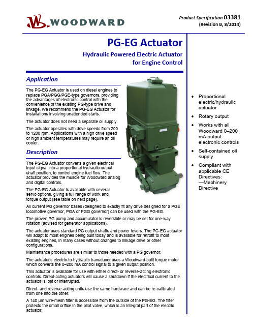
Product Specification 03381(RevisionB, 8/2014)PG‐EG ActuatorHydraulic Powered Electric Actuatorfor Engine ControlApplicationThe PG-EG Actuator is used on diesel engines toreplace PGA/PGG/PGE-type governors, providingthe advantages of electronic control with theconvenience of the existing PG-type drive andlinkage. We recommend the PG-EG Actuator forinstallations involving unattended starts.The actuator does not need a separate oil supply.The actuator operates with drive speeds from 200to 1200 rpm. Applications with a high drive speedor high ambient temperatures may require an oilcooler.DescriptionThe PG-EG Actuator converts a given electricalinput signal into a proportional hydraulic outputshaft position, to control engine fuel flow. Theactuator provides the muscle for Woodward analogand digital controls.The PG-EG Actuator is available with severalservo options, giving a full range of work andtorque output (see table on next page).All current PG governor bases (designed to exactly fit any drive designed for a PGElocomotive governor, PGA or PGG governor) can be used with the PG-EG.The proven PG pump and accumulator is reversible or may be set for one-wayrotation (advised for generator applications).The actuator uses standard PG output shafts and power levers. The PG-EG actuatorwill adapt to most engines being built today and is available for retrofit to mostexisting engines, in many cases without changes to linkage drive or otherconfigurations.Maintenance procedures are similar to those needed with a PG governor.The actuator's electric-to-hydraulic transducer uses a Woodward-built torque motorwhich converts the 0–200 mA control signal to a given output position.This actuator is available for use with either direct- or reverse-acting electroniccontrols. Direct-acting actuators will cause a shutdown if the electrical current to theactuator is lost or interrupted.Direct- and reverse-acting units use the same hardware and can be re-calibratedfrom one into the other.A 140 μm wire-mesh filter is accessible from the outside of the PG-EG. The filterprotects the small orifice in the pilot valve, which is an integral part of the electricactuator.∙ Proportionalelectric/hydraulicactuator∙ Rotary output∙Works with allWoodward 0–200mA outputelectronic controls∙ Self-contained oilsupply∙ Compliant withapplicable CEDirectives:—MachineryDirectiveSpecificationsControl QualitiesHysteresis Within 3% of maximum travel when measured over full travel. Within 0.5% ofmaximum travel when measured over 4% of full travel at 0.1 Hz.Temperature Drift Nominally ±1 degree per 38 °C (100 °F)Time Constant 65 to 85 ms for ±50 mA step with 1379 kPa (200 psi) actuator oil pressure and80 SUS viscosity oilLinearity Within 2.5% of full travelType 12 29 58 200 300 500Sump Capacity 1.4 liters1.5 qt US1.4 liters1.5 qt US1.4 liters1.5 qt US6.2 liters6.5 qt US6.2 liters6.5 qt US6.6 liters7.0 qt USMaximum Work Output16 J12 ft-lb39 J29 ft-lb79 J58 ft-lb237 J175 ft-lb422 J311 ft-lb648 J478 ft-lbRotary Travel 30° 30° 30° 42° 42° 42° Serrated OutputShaft Dimension0.750-48 1.000-48 1.000-48 1.125-48 1.500-60 1.500-60Weight 39–54 kg85–120 lb39–54 kg85–120 lb39–54 kg85–120 lb159 kg350 lb159 kg350 lb227 kg500 lbMaximum DriveSpeed Range200–1200 rpm 200–1200 rpm 200–1200 rpm 200–1200 rpm 200–1200 rpm 200–1200 rpm Recommended DriveSpeed250–1000 rpm 250–1000 rpm 250–1000 rpm 400–1000 rpm 400–1000 rpm 400–1000 rpmInternal Hydraulic Pressure 690 kPa100 psi690 kPa100 psi1724 kPa250 psi1379 kPa200 psi2482 kPa360 psi1931 kPa280 psiAll standard PG bases are available for PG-EG 12, 29, and 58 (see manual 36693, PG Base Assemblies).Construction Base and power block are cast iron. Column is aluminum. Internal parts are case-hardened steel.Vibration Resistance Random: 0.01 G²/Hz at 10 Hz, 0.1 G²/Hz at 100 Hz, 0.1 G²/Hz at 1000 Hz,0.05 G²/Hz at 2000 Hz (12.8 Grms); 3 hours per axis.Woodward advises that PG-EG actuators be equipped with an oil spray to minimizethe effects of vibration.Header Optional FeaturesBooster Servomotor A booster servomotor may be used with the PG-EG to help the prime mover startquickly by moving the actuator output toward the maximum-fuel position at start-up. Governor Heat Exchanger A remote heat exchanger may be required to lower governor oil temperatures inapplications where governor oil tends to exceed 93 °C (200 °F).Drive/Hydraulic SpecificationsDrive Speed and Rotation 200 to 1200 rpm. Available with check valves or with plugs (for fixed CW or CCWoperation). Woodward recommends the use of plugs for applications with drivespeeds above 1000 rpm. NOTE—Drive power for different types of PG-EG actuatorswill vary depending upon speed, internal pump pressure, pump volumetricdisplacement, pump efficiency, and oil viscosity. Contact Woodard if furtherinformation is required.Hydraulic Supply Self-contained sump. See Woodward Manual 25071, Oils for Hydraulic Controls, forspecific recommendations. In most cases, the same type and weight of oils used inthe engine can be used in the governor.Ambient Temperature Range –29 to +93 °C (–20 to +200 °F)Operating Temperature –29 to +104 °C (–20 to +220 °F), within the limits of the oil being used in thegovernor.Electrical SpecificationsElectrical Connector 4 pin connector per MS 3108E-14S-2S (4 socket), located in column.at 20 °C23–26ResistanceCoil36637ManualTechnicalRegulatory ComplianceOther European Compliance:Compliance with the following European Directives or standards does not qualify this product for application of the CE Marking:Machinery Directive:Compliant as partly completed machinery with Directive 2006/42/EC of the EuropeanParliament and the Council of 17 May 2006 on machinery.Woodward 03381 p.4PG-EG 58 Actuator Outline Drawing (PG Base)(Do not use for construction)Woodward 03381 p.5 PG-EG 200 Actuator Outline Drawing(Do not use for construction)PO Box 1519, Fort Collins CO, USA 80522-15191000 East Drake Road, Fort Collins CO 80525Tel.: +1 (970) 482-5811 Fax: +1 (970) 498-3058Distributors & ServiceWoodward has an international network of distributors and service facilities. For your nearest representative, call the Fort Collins plant or see the Worldwide Directory on our website.This document is distributed for informational purposes only. It is not to be construed as creating or becoming part of any Woodward contractual or warranty obligation unless expressly stated in a written sales contract.Copyright © Woodward 2010–2014, All Rights Reserved For more information contact:。
VFPF250数显表说明书

VFPF250数显表说明书
VFPF250数显仪与各类模拟量输出的传感器、变送器配合,完成温度、压力、液位、成分等物理量的测量、变换、显示和控制。
误差小于0.5%FS,并具备调校、数字滤波功能。
适用于标准电压、电流、热电阻、热电偶等信号类型。
2点报警输出,上限报警或下限报警方式可选择。
报警灵敏度独立设定。
4.变送输出(选项),能将测量、变换后的显示值以标准电流、电压形式输出供其它设备使用。
电源:85VAC~265VAC100VDC~380VDC功耗小于4W。
工作环境:0℃~50℃,湿度低于85%R·H无结露。
显示范围:-1999~9999。
小数点位置可设定输入。
信号类型:万能输入,可通过设定选择。
注:0~10VDC输入,订货时需说明,此时仪表不能万能输入。
基本误差:小于0.5%F·S。
测量控制周期:0.2秒。
报警输出:2点继电器输出,触点容量220VAC,3A。
变送输出:
光电隔离:4mA~20mA,0mA~10mA,0mA~20mA直流电流输出。
通过设定选择。
负载能力大干6000,输出分辨力:1/1000。
误差小于±0.5%FS。
变送输出为选项功能。
外供电源用于给变送器供电,输出值与标称值的误差小于±5%,负载能力大于50mA其它规格,。
BF591中文资料

BF591中文资料DATA SHEETProduct speci?cationSupersedes data of September 1994File under Discrete Semiconductors, SC041997Jul02DISCRETE SEMICONDUCTORS BF591; BF593NPN high-voltage transistorsM3D067NPN high-voltage transistors BF591; BF593FEATURESLow current (max. 150mA)High voltage (max. 210V).APPLICATIONSTelephone systems.DESCRIPTIONNPN high-voltage transistor in a TO-202; SOT128B plastic package.PINNINGPIN DESCRIPTION1emitter2collector, connected to mounting base3baseFig.1Simplified outline (TO-202; SOT128B)and symbol.handbook, halfpage213MAM305123QUICK REFERENCE DATASYMBOL PARAMETER CONDITIONS MIN.MAX.UNIT V CBO collector-base voltage open emitterBF591?210VBF593?250VV CEO collector-emitter voltage open baseBF591?170VBF593?210VI CM peak collector current?300mAP tot total power dissipation T amb≤55°C? 1.3Wh FE DC current gain I C=20mA; V CE=5V30?I C=100mA; V CE=6V30?NPN high-voltage transistors BF591; BF593LIMITING VALUESIn accordance with the Absolute Maximum Rating System (IEC134).SYMBOL PARAMETER CONDITIONS MIN.MAX.UNIT V CBO collector-base voltage open emitterBF591?210VBF593?250VV CEO collector-emitter voltage open baseBF591?170VBF593?210VV EBO emitter-base voltage open collector?5VI C collector current (DC)?150mAI CM peak collector current?300mAI BM peak base current?100mAP tot total power dissipation T amb≤55°C? 1.3WT stg storage temperature?65+150°CT j junction temperature?150°CT amb operating ambient temperature?65+150°CTHERMAL CHARACTERISTICSSYMBOL PARAMETER CONDITIONS VALUE UNITR th j-a thermal resistance from junction to ambient in free air73K/WCHARACTERISTICST j=25°C unless otherwise speci?ed.SYMBOL PARAMETER CONDITIONS MIN.MAX.UNIT I CBO collector cut-off current I E=0; V CB=60V?50nAI E=0; V CB=60V; T j=140°C?1μAI EBO emitter cut-off current I C=0; V EB=5V?100nAh FE DC current gain note1I C=20mA; V CE=5V30?I C=100mA; V CE=6V30?I C=150mA; V CE=7V20?Note1.Pulse tes t: t p≤300μs;δ≤0.01.NPN high-voltage transistorsBF591; BF593PACKAGE OUTLINEUNIT b p D E 1L 1L 2(1)max L c c 1E P Q w REFERENCESOUTLINE VERSION EUROPEAN PROJECTIONISSUE DATE IECJEDEC EIAJmm0.80.60.650.50.560.468.68.410.19.92.5413.312.2e 15.08e H E 24.223.82.42.03.83.6P 13.93.70.251.71.5DIMENSIONS (mm are the original dimensions) 2.5SOT128BTO-20297-02-28A c 1DEL 1L 2Lb p cE 1H EPQAP 14.64.4Plastic single-ended leaded (through hole) package; with cooling fin, mountable to heatsink,1 mounting hole; 3 leads (in-line)SOT128B3510 mmscalew MNote1. Plastic flash allowed within this zoneNPN high-voltage transistors BF591; BF593DEFINITIONSData sheet statusObjective speci?cation This data sheet contains target or goal speci?cations for product development. Preliminary speci?cation This data sheet contains preliminary data; supplementary data may be published later. Product speci?cation This data sheet contains ?nal product speci?cations.Limiting valuesLimiting values given are in accordance with the Absolute Maximum Rating System (IEC 134). Stress above one or more of the limiting values may cause permanent damage to the device. These are stress ratings only and operation of the device at these or at any other conditions above those given in the Characteristics sections of the speci?cation is not implied. Exposure to limiting values for extended periods may affect device reliability.Application informationWhere application information is given, it is advisory and does not form part of the speci?cation.LIFE SUPPORT APPLICATIONSThese products are not designed for use in life support appliances, devices, or systems where malfunction of theseproducts can reasonably be expected to result in personal injury. Philips customers using or selling these products for use in such applications do so at their own risk and agree to fully indemnify Philips for any damages resulting from such improper use or sale.NPN high-voltage transistors BF591; BF593NOTESNPN high-voltage transistors BF591; BF593NOTESInternet: /doc/0b12193695.html,Philips Semiconductors – a worldwide companyPhilips Electronics N.V. 1997SCA54All rights are reserved. Reproduction in whole or in part is prohibited without the prior written consent of the copyright owner.The information presented in this document does not form part of any quotation or contract, is believed to be accurate and reliable and may be changed without notice. No liability will be accepted by the publisher for any consequence of its use. Publication thereof does not convey nor imply any license under patent- or other industrial or intellectual property rights.Netherlands: Postbus 90050, 5600PB EINDHOVEN, Bldg.VB,Tel.+31402782785,Fax.+31402788399New Zealand: 2Wagener Place, C.P.O.Box 1041, AUCKLAND,Tel.+6498494160,Fax.+6498497811Norway: Box 1, Manglerud 0612, OSLO,Tel.+4722748000,Fax.+4722748341 Philippines: Philips Semiconductors Philippines Inc.,106Valero St.Salcedo Village, P.O.Box 2108MCC,MAKATI,Metro MANILA, Tel.+6328166380,Fax.+6328173474Poland: Ul.Lukiska 10, PL 04-123WARSZAWA,Tel.+48226122831,Fax.+48226122327Portugal: see Spain Romania: see ItalyRussia: Philips Russia, /doc/0b12193695.html,atcheva 35A, 119048MOSCOW,T el.+70957556918,Fax.+70957556919 Singapore: Lorong 1, Toa Payoh, SINGAPORE 1231,Tel.+653502538,Fax.+652516500Slovakia: see Austria Slovenia: see ItalySouth Africa: S.A. PHILIPS Pty Ltd., 195-215Main Road Martindale,2092JOHANNESBURG, P.O.Box 7430 Johannesburg 2000,Tel.+27114705911,Fax.+27114705494South America: Rua do Rocio 220, 5th floor, Suite 51,04552-903S?o Paulo, S?O PAULO -SP, Brazil,Tel.+55118212333,Fax.+55118291849Spain: Balmes 22, 08007BARCELONA,Tel.+3433016312,Fax.+3433014107 Sweden: Kottbygatan 7, Akalla, S-16485STOCKHOLM,Tel.+4686322000,Fax.+4686322745 Switzerland: Allmendstrasse 140, CH-8027ZüRICH,Tel.+4114882686,Fax.+4114817730Taiwan: Philips Semiconductors, 6F, No.96, Chien Kuo N.Rd.,Sec.1,TAIPEI, Taiwan Tel.+886221342865,Fax.+886221342874Thailand: PHILIPS ELECTRONICS (THAILAND) Ltd.,209/2Sanpavuth-Bangna Road Prakanong, BANGKOK 10260,Tel.+6627454090,Fax.+6623980793Turkey: Talatpasa Cad. No.5, 80640GüLTEPE/ISTANBUL,Tel.+902122792770,Fax.+9021228267 07Ukraine : PHILIPS UKRAINE, 4Patrice Lumumba str., Building B, Floor 7,252042KIEV, Tel.+380442642776, Fax. +380442680461United Kingdom: Philips Semiconductors Ltd., 276Bath Road, Hayes,MIDDLESEX UB35BX, Tel.+441817305000,Fax.+441817548421United States: 811East Arques Avenue, SUNNYVALE, CA 94088-3409,Tel.+18002347381 Uruguay: see South America Vietnam: see SingaporeYugoslavia: PHILIPS, Trg N. Pasica 5/v, 11000BEOGRAD,Tel.+38111625344,Fax.+38111635777 For all other countries apply to: Philips Semiconductors, Marketing &Sales Communications,Building BE-p, P.O.Box 218, 5600MD EINDHOVEN, The Netherlands,Fax.+31402724825Argentina: see South America Australia: 34 Waterloo Road, NORTH RYDE, NSW 2113,Tel.+61298054455,Fax.+61298054466Austria:Computerstr. 6, A-1101 WIEN, P.O. Box 213,Tel.+43160101,Fax.+431601011210Belarus: Hotel Minsk Business Center, Bld.3, r.1211, Volodarski Str.6,220050MINSK, Tel.+375172200733,Fax.+375172200773Belgium: see The Netherlands Brazil:see South AmericaBulgaria:Philips Bulgaria Ltd., Energoproject, 15th floor,51James Bourchier Blvd., 1407SOFIA,T el.+3592689211,Fax.+3592689102Canada: PHILIPS SEMICONDUCTORS/COMPONENTS,T el.+18002347381 China/Hong Kong: 501Hong Kong Industrial Technology Centre,72Tat Chee Avenue, Kowloon Tong, HONG KONG,Tel.+852********,Fax.+852********Colombia: see South America Czech Republic: see AustriaDenmark: Prags Boulevard 80, PB 1919, DK-2300COPENHAGEN S,Tel.+4532882636,Fax.+4531570044Finland:Sinikalliontie 3, FIN-02630ESPOO,Tel.+3589615800,Fax.+358961580920France: 4Rue du Port-aux-Vins, BP317, 92156SURESNES Cedex,Tel.+33140996161,Fax.+33140996427Germany: Hammerbrookstra?e 69, D-20097HAMBURG,T el.+4940235360,Fax.+494023536300 Greece: No.15,25th March Street, GR 17778TAVROS/ATHENS,Tel.+3014894339/239,Fax.+3014814240 Hungary:see AustriaIndia: Philips INDIA Ltd, Shivsagar Estate, A Block, Dr. Annie Besant Rd.Worli, MUMBAI 400018, Tel.+91224938541,Fax.+91224938722Indonesia: see Singapore Ireland: Newstead, Clonskeagh, DUBLIN 14,Tel.+35317640000,Fax.+35317640200Israel: RAPAC Electronics, 7Kehilat Saloniki St, PO Box 18053,TEL AVIV 61180, Tel.+97236450444,Fax.+97236491007Italy: PHILIPS SEMICONDUCTORS, Piazza IV Novembre 3,20124MILANO, Tel.+39267522531,Fax.+39267522557Japan: Philips Bldg 13-37, Kohnan 2-chome, Minato-ku, TOKYO 108,Tel.+81337405130,Fax.+81337405077Korea: Philips House, 260-199Itaewon-dong, Yongsan-ku, SEOUL,Tel.+8227091412,Fax.+8227091415Malaysia: No.76Jalan Universiti, 46200PETALING JAYA, SELANGOR,Tel.+60 37505214,Fax.+6037574880Mexico: 5900Gateway East, Suite 200, EL PASO, TEXAS 79905,Tel.+9-58002347381Middle East: see ItalyPrinted in The Netherlands117047/00/02/pp8 Date of release: 1997Jul 02Document order number: 939775002348。
电机驱动芯片资料知识讲解
A4954双路全桥式DMOS PWM 电动机驱动器特点•低R DS(on)输出•过电流保护(OCP)电动机短路保护oo电动机引脚接地短路保护o电动机引脚电池短路保护•低功耗待机模式•可调PWM 电流限制•同步整流•内部欠压锁定(UVLO)•交叉电流保护描述通过脉宽调制(PWM) 控制两个直流电动机,A4954 能够承受峰值输出电流达±2 安培,并使电压达到40 伏特。
输入端通过应用外部PWM 控制信号以控制直流电动机的速度与方向。
内部同步整流控制电路用来降低脉宽调制(PWM) 操作时的功率消耗。
内部电路保护包括过电流保护、电动机接地或电源短路、因滞后引起的过热关机、V BB欠压监视以及交叉电流保护。
A4954 采用带有外置散热板的16 引脚TSSOP 小型封装(后缀LP)。
该封装为无铅封装,且引脚框采用100% 雾锡电镀。
•功能方框图A4950全桥式DMOS PWM 电动机驱动器特点•低R DS(开)输出•过电流保护(OCP)o电动机短路保护o电动机引脚接地短路保护o电动机引脚电池短路保护•低功耗待机模式•可调PWM 电流限制•同步整流•内部欠压锁定(UVLO)•交叉电流保护描述通过脉宽调制(PWM) 控制直流电动机,A4950 能够提供±3.5 安培的峰值输出电流,工作电压为40 伏特。
该产品可提供输入端子,通过外部施加的PWM 控制信号控制直流电动机的速度与方向。
采用内部同步整流控制电路降低脉宽调制(PWM) 操作时的功率消耗。
内部电路保护包括过电流保护、电动机引脚接地短路或电源短路、带时延的过热关机、V BB欠压监视以及交叉电流保护。
A4950 采用带有外露散热板的8 引脚SOICN 小型封装(后缀LJ)。
该封装为无铅封装,且引脚框采用100% 雾锡电镀。
•功能方框图A4938三相无刷直流电动机预驱动器功能及优点•驱动6 N-通道MOSFET•同步整流,减少功率耗散•内部UVLO 和热关机电路•霍尔元件输入•PWM 电流限制•停机时间保护•FG 输出•待机模式•锁检测保护•过压保护描述A4938 是完整的三相无刷直流(BLDC) 电动机预驱动器,可为所有N 通道功率MOSFET 三相桥的直接大电流门极驱动提供输出。
芝浦直流电机使用说明

额定转
速
最大转
素速
当马达运行于最大转速时,请将 Vsp 调整在 4.0V 到 4.5V 之间。
注释:任何疑问可联系芝蒲。
温度
PT
线圈
环境
对于自动进角的马达无负荷或者较小负荷运转时转速随着vsp的增大而迅速增大转速过高会造成马达剧烈震动有可能损坏测试仪器或马达所以在测试自动进角的马达时请测试过程中请始终保持适当的扭矩来控制马达的转速
芝浦直流无刷马达使用说明
2010-Nov-24
1. 控制接口说明
Nidec Shibaura Corp.
[ Vcc ]
请注意右图所示马达电源关断时的顺序。 1. 缓慢调节 Vsp 到 0 V。 2. 关断 Vm 电源。
[ Vm ] [ Vsp ]
3. 关断 Vcc 电源。
注释:关于 DC 马达的上电顺序,任何疑问可联系芝蒲。
b) 马达保护功能
马达具有过流和过热保护功能
当马达堵转或过负荷运行,限流功能启动,限制马达电流。
当马达过热时,过热保护功能启动,马达停止运行以降低马达的发热。
3. 希望贵公司提供以下资料
Vm
Vm[V]/Im[A]
Vm Vcc = DC15V Vsp
Vcc
Vsp
MotorPG源自GND Vsp[V]在测试评估完该马达后,请提供以下表格中的数据。
对马达调整的好坏,这是很重要数据。
转速
电压
电流
N[rpm] Vm[V] Vcc[V] Vsp[V] Im[A] 功率 IC
c) Vcc 控制回路供电电压 该端口给马达内部信号处理 IC 提供工作电压。 最大额定电压:DC 18V。允许运行电压范围:DC13.5~16.5 V。推荐电压:DC 15V。
BFG591中文资料

150 Ts (oC) 200
Fig.2 Power derating curve.
250
handbook, halfpage
h FE
200
150
100
50
0
10 2
10 1
1
MRA749
10
10 2
IC (mA)
VCE = 12 V.
Fig.3 DC current gain as a function of collector current, typical values.
1995 Sep 04
4
元器件交易网
Philips Semiconductors
NPN 7 GHz wideband transistor
Product specification
BFG591
3.0 Ptot (W)
2.5
2.0
1.5
1.0
0.5
0 0
MGC791
50
100
SYMBOL
PARAMETER
CONDITIONS
VCBO VCEO VEBO IC Ptot Tstg Tj
collector-base voltage collector-emitter voltage emitter-base voltage collector current (DC) total power dissipation storage temperature junction temperature
open emitter open base
up to Ts = 80 °C; note 1 IC = 70 mA; VCE = 8 V IC = Ic = 0; VCE = 12 V; f = 1 MHz IC = 70 mA; VCE = 12 V; f = 1 GHz IC = 70 mA; VCE = 12 V; f = 900 MHz; Tamb = 25 °C IC = 70 mA; VCE = 12 V; f = 900 MHz; Tamb = 25 °C
DLT德力通产品推介说明
DLTK系列乘客电梯产品推介说明一、公司简介湖南德力通电梯有限公司是一家集电梯的研发、制造、销售、安装和维保于一体的综合性企业。
公司座落于南北重要的交通枢纽湖南株洲,水陆交通通讯十分便利。
厂区占地2.5公顷,设有现代化车间(垂直电梯及自动扶梯生产流水线)和国际先进的专业检测、机械加工设备、研发中心等;拥有一批高素质的专业技术人才。
具备年产各类垂直电梯3500台、自动扶梯1000台的生产规模。
目前本厂产品已覆盖全国二十多个省市,并在长沙、广州、深圳、泉州、桂林、扬州、合肥、成都、兰州、潍坊等地设立了办事处及售后服务网点,负责本公司产品在当地的销售及售后服务工作。
德力通电梯有限公司与一些国际著名电梯配件厂商展开全面合作,专业从事高科技、数字化电梯的研究与开发,是世界电梯无机房、无齿轮高科技应用领域内的领先者。
让"用户满意"是德力通人的无上追求,质量与信誉是公司的一贯宗旨。
在生产质量控制与安装、服务过程中严格执行ISO9001-2000与ISO14000、OHSAS18000等相关国际标准管理体系,配备有专业的安装和服务队伍,设立了24小时服务的服务热线,建立起了辐射全国的服务网络和迅捷的备品备件供应体系,为客户提供全方位的服务与支持。
我们热情欢迎宾客用户惠顾、咨询、洽谈订货。
二、产品介绍DLTK系列乘客电梯,是湖南德力通电梯有限公司推出的最新一代高科技绿色环保产品,它具有高效节能、低噪声、无(齿轮箱)油污染、无电源电网污染等优点。
一、最先进的永磁同步拖动系统DLTK系列乘客电梯,采用国际上最先进的永磁同步变频调速拖动技术。
永磁同步电机不需要无功励磁电流,定子铜耗小,功率因素高,并具有低速性、快速性、硬机械特性、停车自闭等优点。
同时,永磁同步电机正常工作时不产生谐波干扰,对电源电网无污染。
二、平稳高效的无齿轮曳引系统DLTK系列乘客电梯,采用无齿轮曳引技术,没有齿轮啮合,彻底消除了齿轮机械传动的振动和噪声,使电梯运行更加平稳,噪声大为降低。
DRV590DWP;DRV590ZQCR;DRV590GQCR;DRV590DWPG4;中文规格书,Datasheet资料

IN– SHUTDOWN GAIN0 GAIN1 PVDD PVDD OUT+
A1 B1 C1 D1 E1 F1 G1
COSC ROSC VDD PVDD PVDD OUT–
PGND (SIDE VIEW) NC – No internal connection NOTE: The shaded terminals are used for thermal connections to the ground plane.
(TJ ≤ 89°C) 1-A DC (100% Duty Cycle) Output Current (TJ ≤ 89°C) Low Supply Voltage Operation from 2.7 V to 5.5 V High Efficiency Generates Less Heat Over-Temperature Protection Short-Circuit Protection PowerPADt SOIC and 4 × 4 mm MicroStar Junior Packages
Supply voltage, VDD, PVDD . . . . . . . . . . . . . . . . . . . . . . . . . . . . . . . . . . . . . . . . . . . . . . . . . . . . . . . . . . . . . –0.3 V to 5.5 V Input voltage, VI . . . . . . . . . . . . . . . . . . . . . . . . . . . . . . . . . . . . . . . . . . . . . . . . . . . . . . . . . . . . . . . . . . –0.3 V to VDD + 0.3 V Continuous total power dissipation . . . . . . . . . . . . . . . . . . . . . . . . . . . . . . . . . . . . . . . . . . See Dissipation Rating Table Operating free-air temperature range, TA . . . . . . . . . . . . . . . . . . . . . . . . . . . . . . . . . . . . . . . . . . . . . . . . . . – 40°C to 85°C Operating junction temperature range, TJ . . . . . . . . . . . . . . . . . . . . . . . . . . . . . . . . . . . . . . . . . . . . . . . . – 40°C to 150°C Storage temperature range, Tstg . . . . . . . . . . . . . . . . . . . . . . . . . . . . . . . . . . . . . . . . . . . . . . . . . . . . . . . . –65°C to 150°C Lead temperature 1,6 mm (1/16 inch) from case for 10 seconds . . . . . . . . . . . . . . . . . . . . . . . . . . . . . . . . . . . . . 260°C
- 1、下载文档前请自行甄别文档内容的完整性,平台不提供额外的编辑、内容补充、找答案等附加服务。
- 2、"仅部分预览"的文档,不可在线预览部分如存在完整性等问题,可反馈申请退款(可完整预览的文档不适用该条件!)。
- 3、如文档侵犯您的权益,请联系客服反馈,我们会尽快为您处理(人工客服工作时间:9:00-18:30)。
元器件交易网
DRV591
SLOS389A – NOVEMBER 2001– REVISED MAY 2002
±3ĆA HIGHĆEFFICIENCY PWM POWER DRIVER
FEATURES D D D D D D D D D
±3-A Maximum Output Current Low Supply Voltage Operation: 2.8 V to 5.5 V High Efficiency Generates Less Heat Over-Current and Thermal Protection Fault Indicators for Over-Current, Thermal and Under-Voltage Conditions Two Selectable Switching Frequencies Internal or External Clock Sync PWM Scheme Optimized for EMI 9×9 mm PowerPAD Quad Flatpack
AVDD ROSC COSC AREF IN+ IN– FAULT1
AGND (Connect to PowerPAD)
To TEC or Laser Diode Anode
DC Control Voltage 1 kΩ 1 kΩ
FAULT0
Shutdown Control
SHUTDOWN
PVDD
PVDD
RECOMMENDED OPERATING CONDITIONS
ቤተ መጻሕፍቲ ባይዱ
PACKAGE DISSIPATION RATINGS
PACKAGE ΘJA(1) (°C/W) ΘJC (°C/W) TA = 25°C POWER RATING
VFP 29.4 1.2 4.1 W (1) This data was taken using 2 oz trace and copper pad that is soldered directly to a JEDEC standard 4-layer 3 in × 3 in PCB.
ÑÑÑÑÑÑÑÑÑÑÑÑÑÑÑÑÑÑÑÑÑÑÑÑÑÑÑÑÑ ÑÑÑ ÑÑ ÑÑÑ ÑÑÑÑÑÑÑÑÑÑÑÑÑÑÑ ÑÑÑÑÑÑÑÑÑÑÑÑÑÑÑ ÑÑÑ ÑÑ ÑÑÑ ÑÑÑÑÑÑÑÑÑÑÑÑÑÑÑÑÑÑÑÑÑÑÑÑÑÑÑÑÑ ÑÑÑÑÑÑÑÑÑÑÑÑÑÑÑ ÑÑÑÑÑÑÑÑÑÑÑÑÑÑÑÑÑÑÑÑÑÑÑÑÑÑÑÑÑ ÑÑÑÑÑÑÑÑÑÑÑÑÑÑÑ ÑÑÑ Ñ ÑÑ ÑÑÑ Ñ ÑÑÑÑÑÑÑÑÑÑÑÑÑÑÑÑÑÑÑÑÑÑÑÑÑÑÑÑÑ ÑÑÑ ÑÑ ÑÑÑ
PVDD
OUT–
OUT–
OUT–
FAULT1 FAULT0 1 µF
10 µH 10 µF
To TEC or Laser Diode Cathode
Please be aware that an important notice concerning availability, standard warranty, and use in critical applications of Texas Instruments semiconductor products and disclaimers thereto appears at the end of this data sheet. PowerPAD is a trademark of Texas Instruments.
Copyright 2002, Texas Instruments Incorporated
元器件交易网 DRV591
SLOS389A – NOVEMBER 2001– REVISED MAY 2002
This integrated circuit can be damaged by ESD. Texas Instruments recommends that all integrated circuits be handled with appropriate precautions. Failure to observe proper handling and installation procedures can cause damage. ESD damage can range from subtle performance degradation to complete device failure. Precision integrated circuits may be more susceptible to damage because very small parametric changes could cause the device not to meet its published specifications.
2
元器件交易网
DRV591
SLOS389A – NOVEMBER 2001– REVISED MAY 2002
ELECTRICAL CHARACTERISTICS
over operating free-air temperature range unless otherwise noted PARAMETER |VOO| |IIH| |IIL| Vn VICM Av Output offset voltage (measured differentially) High-level input current Low-level input current Integrated output noise voltage Common mode voltage range Common-mode Closed-loop voltage gain Full power bandwidth VO Voltage output (measured differentially) rds(on) = 65 mΩ, VDD = 5 V rds(on) = 65 mΩ, VDD = 5 V High side VDD = 5 V, IO = 4 A, TA = 25°C Low side High side VDD = 3.3 V, IO = 4 A, TA = 25°C Maximum continuous current output Status flag output pins (FAULT0, FAULT1) Fault active (open drain output) External clock frequency range Iq Iq(SD) Quiescent current Quiescent current in shutdown mode Output resistance in shutdown Power-on threshold Power-off threshold Thermal trip point ZI Input impedance (IN+, IN–) FAULT0 active Sinking 200 µA For 500 kHz operation For 100 kHz operation VDD = 5 V, No load or filter VDD = 3.3 V, No load or filter VDD = 5 V, SHUTDOWN = 0.8 V SHUTDOWN = 0.8 V 225 45 2 2 0 2 1.7 1.6 130 100 2.8 2.6 250 50 6.2 4.6 0.1 Low side IO = ±1 A, IO = ±3 A, TEST CONDITIONS VI = VDD/2, VDD = 5.5V, VDD = 5.5V, f = <1 Hz to 10 kHz VDD = 5 V VDD = 3.3 V IO = 0 A VI = VDD VI = 0 V 40 1.2 1.2 2.1 2.34 60 4.87 4.61 25 25 25 25 60 65 80 90 3 0.1 275 55 12 8 50 95 95 140 140 3.8 2.1 2.6 MIN TYP 14 MAX 100 1 1 UNIT mV µA µA µV V V/V kHz V mΩ mΩ A V kHz mA µA kΩ V V °C kΩ
ORDERING INFORMATION
TA PowerPAD QUAD FLATPACK (VFP) DRV591VFP(1)
–40°C to 85°C (1) This package is available taped and reeled. To order this packaging option, add an R suffix to the part number (e.g., DRV591VFPR).
VDD 10 µF 1 µF
APPLICATIONS D Thermoelectric Cooler (TEC) Driver D Laser Diode Biasing
OUT+
OUT+
FREQ
PVDD
PVDD
INT/EXT
PVDD
OUT+
1 µF 120 kΩ 220 pF 1 µF
10 µH OUT+ PGND PGND PGND PGND PGND PGND OUT– 10 µF