FREQUENCY DOMAIN IDENTIFICATION OF HARBOUR SEICHES SUMMARY
Common Phase Error due to Phase Noise in OFDM - Estimation and Suppression

COMMON PHASE ERROR DUE TO PHASE NOISE IN OFDM-ESTIMATION AND SUPPRESSIONDenis Petrovic,Wolfgang Rave and Gerhard FettweisV odafone Chair for Mobile Communications,Dresden University of Technology,Helmholtzstrasse18,Dresden,Germany{petrovic,rave,fettweis}@ifn.et.tu-dresden.deAbstract-Orthogonal frequency division multiplexing (OFDM)has already become a very attractive modulation scheme for many applications.Unfortunately OFDM is very sensitive to synchronization errors,one of them being phase noise,which is of great importance in modern WLAN systems which target high data rates and tend to use higher frequency bands because of the spectrum availability.In this paper we propose a linear Kalmanfilter as a means for tracking phase noise and its suppression.The algorithm is pilot based.The performance of the proposed method is investigated and compared with the performance of other known algorithms.Keywords-OFDM,Synchronization,Phase noise,WLANI.I NTRODUCTIONOFDM has been applied in a variety of digital commu-nications applications.It has been deployed in both wired systems(xDSL)and wireless LANs(IEEE802.11a).This is mainly due to the robustness to frequency selective fading. The basic principle of OFDM is to split a high data rate data stream into a number of lower rate streams which are transmitted simultaneously over a number of orthogonal subcarriers.However this most valuable feature,namely orthogonality between the carriers,is threatened by the presence of phase noise in oscillators.This is especially the case,if bandwidth efficient higher order modulations need to be employed or if the spacing between the carriers is to be reduced.To compensate for phase noise several methods have been proposed.These can be divided into time domain[1][2]and frequency domain approaches[3][4][5].In this paper we propose an algorithm for tracking the average phase noise offset also known as the common phase error(CPE)[6]in the frequency domain using a linear Kalmanfilter.Note that CPE estimation should be considered as afirst step within more sophisticated algorithms for phase noise suppression[5] which attempt to suppress also the intercarrier interference (ICI)due to phase noise.CPE compensation only,can however suffice for some system design scenarios to suppress phase noise to a satisfactory level.For these two reasons we consider CPE estimation as an important step for phase noise suppression.II.S YSTEM M ODELAn OFDM transmission system in the presence of phase noise is shown in Fig. 1.Since all phase noise sources can be mapped to the receiver side[7]we assume,without loss of generality that phase noise is present only at the front end of the receiver.Assuming perfect frequency and timing synchronization the received OFDM signal samples, sampled at frequency f s,in the presence of phase noise can be expressed as r(n)=(x(n) h(n))e jφ(n)+ξ(n).Each OFDM symbol is assumed to consist of a cyclic prefix of length N CP samples and N samples corresponding to the useful signal.The variables x(n),h(n)andφ(n)denote the samples of the transmitted signal,the channel impulse response and the phase noise process at the output of the mixer,respectively.The symbol stands for convolution. The termξ(n)represents AWGN noise with varianceσ2n. The phase noise processφ(t)is modelled as a Wiener process[8],the details of which are given below,with a certain3dB bandwidth∆f3dB.,0,1,2...m lX l=,0,1,2...m lR l=Fig.1Block diagram of an OFDM transmission chain.At the receiver after removing the N CP samples cor-responding to the cyclic prefix and taking the discrete Fourier transform(DFT)on the remaining N samples,the demodulated carrier amplitude R m,lkat subcarrier l k(l k= 0,1,...N−1)of the m th OFDM symbol is given as[4]:R m,lk=X m,lkH m,lkI m(0)+ζm,lk+ηm,lk(1)where X m,lk,H m,lkandηm,lkrepresent the transmitted symbol on subcarrier l k,the channel transfer function andlinearly transformed AWGN with unchanged variance σ2n at subcarrier l k ,respectively.The term ζm,l k represents intercarrier interference (ICI)due to phase noise and was shown to be a gaussian distributed,zero mean,randomvariable with variance σ2ICI =πN ∆f 3dB s[7].The term I m (0)also stems from phase noise.It does not depend on the subcarrier index and modifies all subcarriers of one OFDM symbol in the same manner.As its modulus is in addition very close to one [9],it can be seen as a symbol rotation in the complex plane.Thus it is referred to in the literature as the common phase error (CPE)[6].The constellation rotation due to CPE causes unaccept-able system performance [7].Acceptable performance can be achieved if one estimates I m (0)or its argument and compensates the effect of the CPE by derotating the received subcarrier symbols in the frequency domain (see Eq.(1)),which significantly reduces the error rate as compared to the case where no compensation is used.The problem of esti-mating the CPE was addressed by several authors [3][4][10].In [3]the authors concentrated on estimating the argument of I m (0)using a simple averaging over pilots.In [10]the argument of I m (0)was estimated using an extended Kalman filter,while in [4]the coefficient I m (0)itself was estimated using the LS algorithm.Here we introduce an alternative way for minimum mean square estimation (MMSE)[11]of I m (0)using a linear scalar Kalman filter.The algorithm is as [4]pilot based.III.P HASE N OISE M ODELFor our purposes we need to consider a discretized phase noise model φ(n )=φ(nT s )where n ∈N 0and T s =1/f s is the sampling period at the front end of the receiver.We adopt a Brownian motion model of the phase noise [8].The samples of the phase noise process are given as φ(n )=2πf c √cB (n )where f c is the carrier frequency,c =∆f 3dB /πf 2c [8]and B (n )represents the discretizied Brownian motion process,Using properties of the Brownian motion [12]the fol-lowing holds:B (0)=0and B (n +1)=B (n )+dB n ,n ∈N 0where each increment dB n is an independent random variable and dB n ∼√T s N (0,1).Noting that φ(n )=2πf c √cB (n )we can write the discrete time phase noise process equation asφ(n +1)=φ(n )+w (n )(2)where w (n )∼N (0,4π2f 2c cT s )is a gaussian randomvariable with zero mean and variance σ2w =4π2f 2c cT s .IV.CPE E STIMATION U SING A K ALMAN F ILTER Since all received subcarriers within one OFDM symbolare affected by the same factor,namely I m (0),the problem at hand can be seen as an example of estimating a constant from several noisy measurements given by Eq.(1)for which purpose a Kalman filter is well suited [11].For a Kalmanfilter to be used we need to define the state space model of the system.Define first the set L ={l 1,l 2,l 3,...l P }as a subset of the subcarrier set {0,1,...N −1}.Using Eq.(1)one can writeR m,l k =A m,l k I m,l k (0)+εm,l k(3)where A m,l k =X m,l k H m,l k and I m,l k (0)=I m (0)for all k =1,2...,P .Additional indexing of the CPE terms is done here only for convenience of notation.On the other hand one can writeI m,l k +1(0)=I m,l k (0).(4)Equations (3)and (4)are the measurement and processequation of the system state space model,where A m,l k represents the measurement matrix,while the process matrix is equal to 1and I m,l k (0)corresponds to the state of the system.The measuring noise is given by εm,l k which combines the ICI and AWGN terms in Eq.(1),the varianceof which for all l k equals σ2ε=(σ2ICI +σ2n ).The process noise equals zero.Note that the defined state space model is valid only for one OFDM symbol.For the state space model to be fully defined,knowledge of the A m,l k =X m,l k H m,l k is needed.Here we assume to have ideal knowledge of the channel.On the other hand we define the subset L to correspond to the pilot subcarrier locations within one OFDM symbol so that X m,q ,q ∈L are also known.We assume that at the beginning of each burst perfect timing and frequency synchronization is achieved,so that the phase error at the beginning of the burst equals zero.After the burst reception and demodulation,the demodulated symbols are one by one passed to the Kalman filter.For a Kalman filter initialization one needs for eachOFDM symbol an a priori value for ˆI m,l 1(0)and an a priori error variance K −m,1.At the beginning of the burst,when m =1,it is reasonable to adopt ˆI −1,l 1(0)=1.Within each OFDM symbol,say m th,the filter uses P received pilot subcarriers to recursively update the a priori value ˆI −1m,l 1(0).After all P pilot subcarriers are taken into account ˆI m,l P (0)is obtained,which is adopted as an estimate ofthe CPE within one OFDM symbol,denoted as ˆIm (0).The Kalman filter also provides an error variance of the estimateof I m,l P (0)as K m,P .ˆI m,l P(0)and K m,P are then used as a priori measures for the next OFDM symbol.The detailed structure of the algorithm is as follows.Step 1:InitializationˆI −m,l 1(0)=E {I −m,l 1(0)}=ˆI m −1(0)K −m,1=E {|I m (0)−ˆIm −1(0)|2}∼=E {|φm −ˆφm −1|2}=σ2CP E +K m −1,Pwhere σ2CP E =4π2N 2+13N +N CP ∆f 3dBf s(see [10]),K 0,P =0and φm =arg {I m (0)}.Repeat Step2and Step3for k=1,2,...,P Step2:a-posteriori estimation(update)G m,k=K−m,kH H m,lkH m,lkK−m,kH Hm,l k+(σ2ICI+σ2n)ˆIm,l k (0)=ˆI−m,l k(0)+G m,k[R m,lk−H m,l kˆI−m,l k(0)]K m,k=(1−G m,k H m,lk )K−m,kStep3:State and error variance propagationK−m,k+1=K m,k(5)ˆI−m,l k+1(0)=ˆI m,lk(0)Note that no matrix inversions are required,since the state space model is purely scalar.V.CPE C ORRECTIONThe easiest approach for CPE correction is to derotate all subcarriers l k of the received m th symbol R m,lkby φm=−arg{ˆI m(0)}.Unambiguity of the arg{·}function plays here no role since any unambiguity which is a multiple of2πrotates the constellation to its equivalent position in terms of its argument.The presented Kalmanfilter estimation algorithm is read-ily applicable for the decision feedback(DF)type of algo-rithm presented in[4].The idea there was to use the data symbols demodulated after thefirst CPE correction in a DFE manner to improve the quality of the estimate since that is increasing the number of observations of the quantity we want to estimate.In our case that would mean that after thefirst CPE correction the set L={l1,l2,l3,...l P}of the subcarriers used for CPE estimation,which previously corresponded to pilot subcarriers,is now extended to a larger set corresponding to all or some of the demodulated symbols. In this paper we have extended the set to all demodulated symbols.The Kalmanfilter estimation is then applied in an unchanged form for a larger set L.VI.N UMERICAL R ESULTSThe performance of the proposed algorithm is investigated and compared with the proposal of[4]which is shown to outperform other known approaches.The system model is according to the IEEE802.11a standard,where64-QAM modulation is used.We investigate the performance in AWGN channels and frequency selective channels using as an example the ETSI HiperLAN A-Channel(ETSI A). Transmission of10OFDM symbols per burst is assumed.A.Properties of an EstimatorThe quality of an estimation is investigated in terms of the mean square error(MSE)of the estimator for a range of phase noise bandwidths∆f3dB∈[10÷800]Hz.Table1 can be used to relate the phase noise bandwidth with other quantities.Figures2and3compare the MSE of the LS estimator from[4]and our approach for two channel types and both standard correction and using decision feedback. Note that SNRs are chosen such that the BER of a coded system after the Viterbi algorithm in case of phase noise free transmission is around1·10−4.Kalmanfilter shows better performance in all cases and seems to be more effective for small phase noise bandwidths. As expected when DF is used the MSE of an estimator is smaller because we are taking more measurements into account.Fig.2MSE of an estimator for AWGN channel.Fig.3MSE of an estimator for ETSI A channel.Table 1Useful relationsQuantitySymbolRelationTypical values for IEEE802.11aOscillator constant c [1radHz]8.2·10−19÷4.7·10−18Oscillator 3dB bandwidth ∆f 3dB [Hz]∆f 3dB =πf 2cc 70÷400Relative 3dB bandwidth ∆f 3dB ∆f car∆f 3dBfsN 2·10−4÷13·10−4Phase noise energy E PN [rad]E PN =4π∆f 3dB∆fcar0.0028÷0.016Subcarrier spacing∆f car∆f car =f s N312500HzB.Symbol Error Rate DegradationSymbol error rate (SER)degradation due to phase noise is investigated also for a range of phase noise bandwidths ∆f 3dB ∈[10÷800]Hz and compared for different correc-tion algorithms.Ideal CPE correction corresponds to the case when genie CPE values are available.In all cases simpleconstellation derotation with φ=−arg {ˆIm (0)}is used.Fig.4SER degradation for AWGN channel.In Figs.4and 5SER degradation for AWGN and ETSI A channels is plotted,respectively.It is interesting to note that as opposed to the ETSI A channel case in AWGN channel there is a gap between the ideal CPE and both correction approaches.This can be explained if we go back to Eq.(1)where we have seen that phase noise affects the constellation as additive noise.Estimation error of phase noise affects the constellation also in an additive manner.On the other hand the SER curve without phase noise in the AWGN case is much steeper than the corresponding one for the ETSI A channel.A small SNR degradation due to estimation errors will cause therefore large SER variations.This explains why the performance differs much less in the ETSI A channel case.Generally from this discussion a conclusion can be drawn that systems with large order of diversity are more sensitive to CPE estimation errors.Note that this ismeantFig.5SER degradation for ETSI A channel.not in terms of frequency diversity but the SER vs.SNR having closely exponential dependence.It can be seen that our approach shows slightly better performance than [4]especially for small phase noise bandwidths.What is also interesting to note is,that DF is not necessary in the case of ETSI A types of channels (small slope of SER vs.SNR)while in case of AWGN (large slope)it brings performance improvement.VII.C ONCLUSIONSWe investigated the application of a linear Kalman filter as a means for tracking phase noise and its suppression.The proposed algorithm is of low complexity and its performance was studied in terms of the mean square error (MSE)of an estimator and SER degradation.The performance of an algorithm is compared with other algorithms showing equivalent and in some cases better performance.R EFERENCES[1]R.A.Casas,S.Biracree,and A.Youtz,“Time DomainPhase Noise Correction for OFDM Signals,”IEEE Trans.on Broadcasting ,vol.48,no.3,2002.[2]M.S.El-Tanany,Y.Wu,and L.Hazy,“Analytical Mod-eling and Simulation of Phase Noise Interference in OFDM-based Digital Television Terrestial Broadcast-ing Systems,”IEEE Trans.on Broadcasting,vol.47, no.3,2001.[3]P.Robertson and S.Kaiser,“Analysis of the effects ofphase noise in OFDM systems,”in Proc.ICC,1995.[4]S.Wu and Y.Bar-Ness,“A Phase Noise SuppressionAlgorithm for OFDM-Based WLANs,”IEEE Commu-nications Letters,vol.44,May1998.[5]D.Petrovic,W.Rave,and G.Fettweis,“Phase NoiseSuppression in OFDM including Intercarrier Interfer-ence,”in Proc.Intl.OFDM Workshop(InOWo)03, pp.219–224,2003.[6]A.Armada,“Understanding the Effects of PhaseNoise in Orthogonal Frequency Division Multiplexing (OFDM),”IEEE Trans.on Broadcasting,vol.47,no.2, 2001.[7]E.Costa and S.Pupolin,“M-QAM-OFDM SystemPerformance in the Presence of a Nonlinear Amplifier and Phase Noise,”IEEE mun.,vol.50, no.3,2002.[8]A.Demir,A.Mehrotra,and J.Roychowdhury,“PhaseNoise in Oscillators:A Unifying Theory and Numerical Methods for Characterisation,”IEEE Trans.Circuits Syst.I,vol.47,May2000.[9]S.Wu and Y.Bar-ness,“Performance Analysis of theEffect of Phase Noise in OFDM Systems,”in IEEE 7th ISSSTA,2002.[10]D.Petrovic,W.Rave,and G.Fettweis,“Phase NoiseSuppression in OFDM using a Kalman Filter,”in Proc.WPMC,2003.[11]S.M.Kay,Fundamentals of Statistical Signal Process-ing vol.1.Prentice-Hall,1998.[12]D.J.Higham,“An Algorithmic Introduction to Numer-ical Simulation of Stochastic Differential Equations,”SIAM Review,vol.43,no.3,pp.525–546,2001.。
无线电引信频域恒虚警率目标检测算法
第32卷第1期2010年2月探测与控制学报Journal of Detection &C ontrolVol 132No 11Feb 12010*收稿日期:2009-09-07 修回日期:2009-11-03作者简介:石润龙(1984-),男,陕西铜川人,硕士,助工,研究方向:信号处理。
E -ma il:shirl1984@163.co m 。
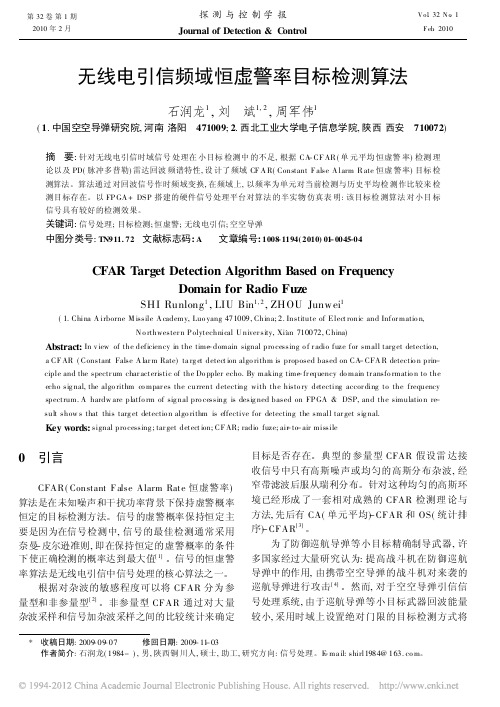
无线电引信频域恒虚警率目标检测算法石润龙1,刘 斌1,2,周军伟1(1.中国空空导弹研究院,河南洛阳 471009;2.西北工业大学电子信息学院,陕西西安 710072)摘 要:针对无线电引信时域信号处理在小目标检测中的不足,根据CA-CF AR (单元平均恒虚警率)检测理论以及PD(脉冲多普勒)雷达回波频谱特性,设计了频域CF A R(Constant F alse A larm R ate 恒虚警率)目标检测算法。
算法通过对回波信号作时频域变换,在频域上,以频率为单元对当前检测与历史平均检测作比较来检测目标存在。
以FP GA +DSP 搭建的硬件信号处理平台对算法的半实物仿真表明:该目标检测算法对小目标信号具有较好的检测效果。
关键词:信号处理;目标检测;恒虚警;无线电引信;空空导弹中图分类号:TN911.72 文献标志码:A 文章编号:1008-1194(2010)01-0045-04CFAR Target Detection Algorithm Based on FrequencyDomain for Radio FuzeSHI Runlong 1,LIU Bin 1,2,ZHOU Junw ei 1(1.China A irborne M issile A cademy,Luo yang 471009,China;2.Institute of Elect ronic and Infor matio n,N o rthwester n P olytechnical U niver sity,Xi'an 710072,China)Abstract:In v iew of the deficiency in the time-domain signal pro cessing o f r adio fuze for small targ et detectio n,a CF AR (Constant False A lar m Rate)ta rg et detect ion algo rithm is proposed based on CA -CFA R detectio n prin -ciple and the spectr um char acteristic of the Do ppler echo.By making time -fr equency do main tr ansfo rmatio n to the echo sig nal,the algo rithm co mpar es the current detecting with the histo ry detecting accor ding to the frequency spectrum.A hardw are platfo rm of sig nal pro cessing is desig ned based on FP GA &DSP,and the simulatio n re -sult show s that this targ et detectio n algo rithm is effective for detecting the small tar get sig nal.Key words:signal pro cessing ;tar get detect ion;CF AR;radio fuze;air-to -air missile 0 引言CFAR(Constant False Alarm Rate 恒虚警率)算法是在未知噪声和干扰功率背景下保持虚警概率恒定的目标检测方法。
Sennheiser ew 系列无线麦克风系统用户手册说明书

The ew 322 G3 consists of the same components as ew 312 G3but with a compact cardioid clip-on microphone.The ew 352 G3 consists of the same components as ew 312 G3but with a headworn cardioid microphone.FEATURESSturdy metal housing(transmitter and receiver)42 MHz bandwidth: 1,680 tunable UHF frequencies for interference-free reception20 frequency banks with up to 24 compatible frequenciesEthernet port for connecting to theWireless Systems Manager (WSM) software for control via computer High-quality true diversity receptionPilot tone squelch for eliminating RF inter- ference when transmitter is turned off Automatic frequency scan feature searches for available frequencies Enhanced AF frequency rangeIncreased range for audio sensitivity Wireless synchronization of transmitter parameter from receiverUser-friendly menu operation with more control optionsIlluminated graphic display, receiver also shows transmitter settingsAuto-Lock function avoids accidental changing of settingsHDX compander for crystal-clear sound Transmitter feature battery indicatation in 4 steps, also shown on receiver display Programmable Mute function Integrated Equalizer and Soundcheck modeContacts for recharging BA 2015 accupack directly in the transmitter Wide range of accessories adapts the system to any requirementThe ew 312 G3 is a wireless microphone set, consisting of a True Diversityreceiver, a bodyworn transmitter, a compact omni directional clip-on micropho-ne plus accessories.The bodypack transmitter features charging contacts for the optional recharge-able battery. Sync up the bodypack to the receiver wirelessly with the new wireless sync. Backlit graphic displays make them easy to read under all lighting conditions.ew 300 Setsew 312 G3 Presentation Set ew 322 G3 Presentation Set ew 352 G3 Head Setew 335/345/365 G3 Vocal SetsFEATURESew 335 G3/ew 345 G3/ew 365 G3 Vocal SetsSee above mentioned list of features plus Programmable Mute switch, easyaccessableHandheld transmitter with easy-exchangeable microphone heads from evolution series The ew 335 G3 is a wireless microphone set, consisting of a True Diversity receiver, a handheld transmitter with e 835 microphone head plus accessories. It is versatile for every style of music and presentations. A wireless link from receiver to the transmitter allows synchronization of frequencies for easy setup. Backlit graphic displays make them easy to read under all lighting conditions. The ew 345 G3 consists of the same components as ew 335 G3but with an e 845 microphone head.The ew 365 G3consists of the same components as ew 335 G3but with an e 865 microphone head.ARCHITECT’S SPECIFICATIONSew 312 G3 Presentation SetComplete plug & play wireless microphone set with clip-on microphone (condenser, omni-directional) from Sennheiser evolution series for multi-purpose application. The devices shall have metal housings for rugged use. 42 MHz bandwidth with 1,680 tunable frequencies. 20 banks with up to 24 compatible frequencies, 1 bank for individual selectable frequencies, scan function and wireless synchronization to the transmitter for easy setup. HDX compander delivers high-quality sound performance. All parameters of transmitter and receiver can be monitored and controlled via Wireless Systems Manager (WSM) software from PC. The transmitter shall have a sensitivity range of 48 dB. The receiver offers a maximum output level of +18 dBu (+6 dB gain). True Diversity and pilot tone squelch for interference-free reception. Charging contacts on transmitter for recharging BA 2015 accupack directly in the transmitter shall be available. 3-step battery + LowBattery indication on transmitter and receiver shall give reliable information on operation time.Menu operation, auto-lock function and illuminated graphic displays on transmitter and receiver for user-friendly operation.A RF Mute function on transmitter and receiver allows offline settings.An easy accessable Mute switch on the transmitter can be programmed for AF on/off, RF on/off.A suitable Remote Mute Switch option also allows push-to-talk and push-to-muteAn equalizer and soundcheck mode is inte g rated in the receiver.ew 322 G3 Presentation SetComplete plug & play wireless microphone set with clip-on microphone (electret, cardioid) from Sennheiser evolution series for multi-purpose application. Further discription see paragraph ew 312 G3.ew 352 G3 Head SetComplete plug & play wireless microphone set with headworn microphone (condenser, cardioid) for hands-free application. Further discription see paragraph ew 312 G3.ew 335 G3 Vocal SetComplete plug & play wireless microphone set with easy-exchangeable e 835 microphone head (dynamic, cardioid) from Sennheiser evolution series for multi-purpose application. Further discription see paragraph ew 312 G3.ew 345 G3 Vocal SetComplete plug & play wireless microphone set with easy-exchangeable e 845 microphone head (dynamic, supercardioid) from Sennheiser evolution series for multi-pur p ose application. Further discription see paragraph ew 312 G3.ew 365 G3 Vocal SetComplete plug & play wireless microphone set with easy-exchangeable e 865 microphone head (electret-condenser, supercardioid) from Sennheiser evolution series for multi-purpose application. Further discription see paragraph ew 312 G3.SySTEMRF frequency range ................................................516.....865 MHzTransmission/receiving frequencies ...................1,680Frequency banks ..................................................... 20 (factory presets)6 (user presets)Presets .......................................................................24 max.Switching bandwidth .............................................42 MHzCompander ...............................................................HDXSignal-to-noise ratio ..............................................> 115 dB(A)THD, total harmonic distortion ............................< 0.9 %RECEIvERAF Frequency response..........................................25…18,000 HzAntenna connectors ...............................................BNC, 50 OhmAudio outputs .......................................................... X LR: +18 dBu max6.3 mm jack: +10 dBu maxDimensions ...............................................................212 x 202 x 43 mmWeight .......................................................................980 gTRANSMITTERRF output power .....................................................10/30 mW switchableOperating time ........................................................typ. 8hInput voltage range ................................................1.8 v lineInput voltage range ................................................2.4 v lineDimensions ...............................................................82 x 64 x 24 mmWeight .......................................................................~ 160 gMICROPHONETransducer; Microphone type ...............................permanent polarizedAF sensitivity ...........................................................1.6 mv/PaFrequency response ...............................................80.....18,000 HzPick-up pattern ........................................................omni-directionalContinued on page 5EM 300Modulation ...............................................................wideband FMRF frequency range ................................................ 516 – 558, 566 – 608, 626 – 668, 734 –776, 780 – 822, 823 – 865 MHz Transmission/receiving frequencies ...................1,680, tuneable in steps of 25 kHzReceiving frequencies ............................................ 1,680 frequencies, tuneable in steps of 25 kHz20 frequency banks, each with up to 24 factory-preset channels,intermodulation-free20 frequency banks with up to 24 user programmable channelsSwitching bandwidth .............................................42 MHzNominal/peak deviation .......................................±24 kHz/±48 kHzReceiver principle ....................................................true diversitySensitivity (with HDX, peak deviation) .............< 2 μv for 52 dBA rms S/NAdjacent channel rejection ...................................typ. ≥ 75 dBIntermodulation attenuation ...............................typ. ≥ 70 dBBlocking .....................................................................≥ 75 dBSquelch ...................................................................... O ff, 5 to 25 dBμv, adjustable in steps of 2 dBPilot tone squelch ...................................................can be switched offAntenna inputs .......................................................2 BNC socketsCompander system .................................................Sennheiser HDXEQ presets (switchable, affect the line and monitor outputs):Preset 1: “Flat”Preset 2: “Low Cut” ................................................–3 dB at 180 HzPreset 3: “Low Cut/High boost” .......................... –3 dB at 180 Hz+6 dB at 10 kHzPreset 4: “High Boost” ...........................................+6 dB at 10 kHzS/N ratio (1 mv, peak deviation) ........................≥ 115 dBATHD .............................................................................≤ 0.9 %AF output voltage (at peak deviation,1 kHz AF) .................................................................. ¼” (6.3 mm) jack socket (unbalanced): +12 dBuXLR socket (balanced): +18 dBuAdjustment range of audio output level ........... 48 dB, adjustable in steps of 3 dB +6 dB gain reserveTemperature range .................................................–10 °C to +55 °CPower supply............................................................12 vPower consumption:...............................................350 mADimensions ...............................................................approx. 202 x 212 x 43 mmWeight (incl. batteries) .........................................approx. 980 gIn compliance with .................................................. C E, FCC, ETS 300422, ETS 300445MAINS UNITInput voltage............................................................100 to 240 v~, 50/60 HzPower/current consumption ................................max. 120 mAOutput voltage ........................................................12 vSecondary output current .....................................400 mATemperature range .................................................–10 °C to +40 °CIn compliance with .................................................. C E, FCC, IC, ETS 300422, ETS 300445Continued on page 6SK 300 and SKM 300Modulation ...............................................................wideband FMRF frequency range ................................................ 516 – 558, 566 – 608, 626 – 668, 734 –776, 780 – 822, 823 – 865 MHz Transmission/receiving frequencies ...................1,680, tuneable in steps of 25 kHzReceiving frequencies ............................................ 1,680 frequencies, tuneable in steps of 25 kHz20 frequency banks, each with up to 24 factory-preset channels, intermodulation-free6 frequency banks with up to 24 user programmable channelsSwitching bandwidth .............................................42 MHzNominal/peak deviation .......................................±24 kHz/±48 kHzFrequency stability .................................................≤ ±15 ppmRF output power at 50 O......................................typ. 10/30 mW, switchablePilot tone squelch ...................................................can be switched offAF characteristicsCompander system .................................................Sennheiser HDXAF frequency responseSK ................................................................................ m icrophone: 80 –18,000 Hzline: 25 –18,000 HzSKM ............................................................................80 –18,000 HzS/N ratio (1 mv, peak deviation) ........................≥ 115 dBATHD .............................................................................≤ 0.9 %Max. input voltage (SK) microphone/line ........3 vrmsInput impedance (SK) microphone/line ...........40 k O, unbalanced/1 M OInput capacitance (SK) ..........................................switchableAdjustment range of input sensitivity .............. S K: 60 dB, adjustable in steps of 3 dBSKM: 48 dB, adjustable in steps of 6 dBIn compliance with .................................................. C E, FCC, IC, ETS 300422, ETS 300445OvERALL DEvICETemperature range .................................................−10 °C to + 55 °CPower supply ........................................................... 2 AA size batteries, 1.5 v orBA 2015 accupackNominal voltage .....................................................2.4 vCurrent consumption: at nominal voltage ........typ. 180 mA (30 mW)with switched-off transmitter .............................≤ 25 μAOperating time .......................................................typ. 8 hrsDimensions ............................................................... S K: approx. 82 x 64 x 24 mmSKM: approx. Ø 50 x 265 mmWeight (incl. batteries) ......................................... S K: approx. 160 gSKM: approx. 450 gIn compliance with .................................................. C E, FCC, IC, ETS 300422, ETS 300445Continued on page 7Microphones (SK 300)ME 2ME 3-ew ME 4Microphone type .............................condenser condenser condenserSensitivity .........................................20 mv/Pa 1.6 mv/Pa40 mv/PaPick-up pattern ................................omni-directional cardioid cardioidMax. SPL ............................................130 dB SPL150 dB SPL120 dB SPL Microphone heads (SKM 300)MMD 835-1MMD 845-1MMK 865-1Radio microphone type .................dynamic dynamic condenserSensitivity ......................................... 2.1 mv/Pa 1.6 mv/Pa 1.6 mv/PaPick-up pattern ................................cardioid super-cardioid cardioid/super-cardioid,switchableMax. SPL ............................................154 dB SPL154 dB SPL152 dB SPL Frequency response .......................80.....18,000 Hz80.....18,000 Hz80.....18,000 HzDELIVERY INCLUDES for ew 312 / ew 322 / ew 352 G31 EM 300 G3 rack-mount receiver1 SK 300 G3 bodypack transmitter1 ME2 clip-on microphone (omni-directional) or1 ME 4 clip-on microphone (cardioid) or1 ME 3-ew headset microphone (cardioid)1 GA 3 rack mount1 NT2 power supply unit2 Antennas2 AA batteries1 Instruction manualDELIVERY INCLUDES for ew 335 / ew 345 / ew 365 G31 S KM 300-835 handheld transmitterwith cardioid dynamic head or1 S KM 300-845 handheld transmitterwith super-cardioid dynamic head or1 S KM 300-865 handheld transmitterwith super-cardioid condenser head1 EM 300 G3 rack receiver1 MZQ 1 microphone clip1 NT2 power supply unit2 Antennas1 GA 3 Rack mount kit2 AA batteries1 Instruction ManualPOLAR PATTERN0510152025dB30°30°60°60°90°90°120°150°120°150°0°180°125 Hz 250 Hz 500 Hz 1000 Hz2000 Hz 4000 Hz 8000 Hz 16000 HzMMD 835-1MME 865-1MMD 845-10510152025dB30°30°60°60°90°90°120°150°120°150°0°180°125 Hz 250 Hz 500 Hz 1000 Hz2000 Hz 4000 Hz 8000 Hz 16000 Hz0510152025dB30°30°60°60°90°90°120°150°120°150°0°180°125 Hz 250 Hz 500 Hz 1000 Hz2000 Hz 4000 Hz 8000 Hz 16000 HzME 3-ewME 4-ew0510152025dB30°30°60°60°90°90°120°150°120°150°0°180°125 Hz 250 Hz 500 Hz 1000 Hz2000 Hz 4000 Hz 8000 Hz 16000 Hz0510152025dB30°30°60°60°90°90°120°150°120°150°0°180°125 Hz 250 Hz 500 Hz 1000 Hz2000 Hz 4000 Hz 8000 Hz 16000 HzPRODUCT VARIANTSew 312 G3 Presentation Set Cat. No. ew 312 G3-A-EU 516 – 558 MHz 503112 ew 312 G3-A-US 516 – 558 MHz 503330 ew 312 G3-G-EU 566 – 608 MHz 503331 ew 312 G3-G-US 566 – 608 MHz 503332 ew 312 G3-B-EU 526 – 668 MHz 503333 ew 312 G3-B-US 526 – 668 MHz 503334 ew 312 G3-C-EU 734 –776 MHz 503335 ew 312 G3-C-US 734 –776 MHz 503336 ew 312 G3-D-EU 780 – 822 MHz 503337 ew 312 G3-D-EU-X 780 – 822 MHz 503338 ew 312 G3-D-UK 780 – 822 MHz 503339 ew 312 G3-E-EU 823 – 865 MHz 503340 ew 312 G3-E-EU-X 823 – 865 MHz 503341 ew 312 G3-E-UK 823 – 865 MHz 503342 ew 312 G3-GB 606 – 648 MHz 504649 ew 322 G3 Presentation Set Cat. No. ew 322 G3-E-UK 823 – 865 MHz 503357 ew 322 G3-A-EU 516 – 558 MHz 503113 ew 322 G3-A-US 516 – 558 MHz 503345 ew 322 G3-G-EU 566 – 608 MHz 503346 ew 322 G3-G-US 566 – 608 MHz 503347 ew 322 G3-B-EU 626 – 668 MHz 503348 ew 322 G3-B-US 626 – 668 MHz 503349 ew 322 G3-C-EU 734 –776 MHz 503350 ew 322 G3-C-US 734 –776 MHz 503351 ew 322 G3-D-EU 780 – 822 MHz 503352 ew 322 G3-D-EU-X 780 – 822 MHz 503353 ew 322 G3-D-UK 780 – 822 MHz 503354 ew 322 G3-E-EU 823 – 865 MHz 503355 ew 322 G3-E-EU-X 823 – 865 MHz 503356 ew 322 G3-GB 606 – 648 MHz 504650 ew 352 G3 Presentation Set Cat. No. ew 352 G3-A-EU 516 – 558 MHz 503114 ew 352 G3-A-US 516 – 558 MHz 503360 ew 352 G3-G-EU 566 – 608 MHz 503361 ew 352 G3-G-US 566 – 608 MHz 503362 ew 352 G3-B-EU 526 – 668 MHz 503363 ew 352 G3-B-US 526 – 668 MHz 503364 ew 352 G3-C-EU 734 –776 MHz 503365 ew 352 G3-C-US 734 –776 MHz 503366 ew 352 G3-D-EU 780 – 822 MHz 503367 ew 352 G3-D-EU-X 780 – 822 MHz 503368 ew 352 G3-D-UK 780 – 822 MHz 503369 ew 352 G3-E-EU 823 – 865 MHz 503370 ew 352 G3-E-EU-X 823 – 865 MHz 503371 ew 352 G3-E-UK 823 – 865 MHz 503372 ew 352 G3-GB 606 – 648 MHz 504651ew 335 G3 Vocal Set Cat. No. ew 335 G3-A-EU 516 – 558 MHz 503115 ew 335 G3-A-US 516 – 558 MHz 503375 ew 335 G3-G-EU 566 – 608 MHz 503376 ew 335 G3-G-US 566 – 608 MHz 503377 ew 335 G3-B-EU 526 – 668 MHz 503378 ew 335 G3-B-US 526 – 668 MHz 503379 ew 335 G3-C-EU 734 –776 MHz 503380 ew 335 G3-C-US 734 –776 MHz 503381 ew 335 G3-D-EU 780 – 822 MHz 503382 ew 335 G3-D-EU-X780 – 822 MHz 503383 ew 335 G3-D-UK 780 – 822 MHz 503384 ew 335 G3-E-EU 823 – 865 MHz 503385 ew 335 G3-E-EU-X823 – 865 MHz 503386 ew 335 G3-E-UK 823 – 865 MHz 503387 ew 335 G3-GB 606 – 648 MHz 504652 ew 345 G3 Vocal Set Cat. No. ew 345 G3-A-EU 516 – 558 MHz 503116 ew 345 G3-A-US 516 – 558 MHz 503390 ew 345 G3-G-EU 566 – 608 MHz 503391 ew 345 G3-G-US 566 – 608 MHz 503392 ew 345 G3-B-EU 526 – 668 MHz 503393 ew 345 G3-B-US 526 – 668 MHz 503394 ew 345 G3-C-EU 734 –776 MHz 503395 ew 345 G3-C-US 734 –776 MHz 503396 ew 345 G3-D-EU 780 – 822 MHz 503397 ew 345 G3-D-EU-X780 – 822 MHz 503398 ew 345 G3-D-UK 780 – 822 MHz 503399 ew 345 G3-E-EU 823 – 865 MHz 503400 ew 345 G3-E-EU-X823 – 865 MHz 503401 ew 345 G3-E-UK 823 – 865 MHz 503402 ew 345 G3-GB 606 – 648 MHz 504653 ew 365 G3 Vocal Set Cat. No. ew 365 G3-A-EU 516 – 558 MHz 503117 ew 365 G3-A-US 516 – 558 MHz 503405 ew 365 G3-G-EU 566 – 608 MHz 503406 ew 365 G3-G-US 566 – 608 MHz 503407 ew 365 G3-B-EU 526 – 668 MHz 503408 ew 365 G3-B-US 526 – 668 MHz 503409 ew 365 G3-C-EU 734 –776 MHz 503410 ew 365 G3-C-US 734 –776 MHz 503411 ew 365 G3-D-EU 780 – 822 MHz 503412 ew 365 G3-D-EU-X780 – 822 MHz 503413 ew 365 G3-D-UK 780 – 822 MHz 503414 ew 365 G3-E-EU 823 – 865 MHz 503415 ew 365 G3-E-EU-X823 – 865 MHz 503416 ew 365 G3-E-UK 823 – 865 MHz 503417 ew 365 G3-GB 606 – 648 MHz 504654RECOMMENDED ACCESSORIESCat. No. ME 4-ew – Clip-on microphone,cardioid, black 503156 AM 2 – Antenna Mount kit 009912 CC 3 – System Case 503168L 2015 – Charging unit 009928 BA 2015 – Rechargeable battery pack 009950 ASA 1 – Active antenna splitter 503165 NT 1-1 – plug-in mains unit forASA 1 & L 2015 E U: 503158US: 503873UK: 503874 NT 3-1 – Plug-in mains unit for L 2015 E U: 503159US: 503876UK: 503877 A 1031-U – Antenna 004645A 2003-UHF – Directional Antenna 003658 AB 3 – Antenna booster 505550 Ear Set 1-ew – Ear-worn microphone,omni, black 504232 Ear Set 1-ew-3 – Ear-worn microphone,omni, beige 504237 Ear Set 4-ew – Ear-worn microphone,cardioid, black 504236 Ear Set 4-ew-3 – Ear-worn microphone,cardioid, beige 504234 MKE 1-ew – Clip-on microphone,omni-directional, black 502876 MKE 1-ew-1 – Clip-on microphone,omni, white 502877 MKE 1-ew-2 – Clip-on microphone,omni, brown 502878 MKE 1-ew-3 – Clip-on microphone, beige 502879 MKE 2-ew Gold – Clip-on microphone,omni, black 009831 MKE 2-ew-3 Gold – Clip-on microphone,omni, beige 009832 MKE 40-ew – Clip-on microphone,cardioid, black 500527Cat. No. HSP 4-ew – Headworn microphone,cardioid, black 009864 HSP 4-ew-3 – Headworn microphone,cardioid, beige 009867 HSP 2-ew – Headworn microphone,omni, black 009866 HSP 2-ew-3 – Headworn microphone,omni, beige 009872 CI 1 – Instrument cable 503163ew 335 / ew 345 / ew 365 G3 Vocal SetsMMD 835-1 – evolution microphone head 502575 MMD 845-1 – evolution microphone head 502576 MME 865-1 – evolution microphone head 502581 MZW 1 – Windshield 004839 KEN 2 – Identification rings 530195 LA 2 – Charging adapter forhandheld microphones 503162 CC 3 – System case 503168Sennheiser electronic GmbH & Co. KG Am Labor 1, 30900 Wedemark, Germany 0 4 / 1 3 S e n n h e i s e r i s a r e g i s t e r e d t r a d e m a r k o f S e n n h e i s e r e l e c t r o n i c G m b H & C o . K G . w w w . s e n n h e i s e r . c o m . C o p y r i g h t ©0 4 / 2 0 1 3 . A l l r i g h t s r e s e r v e d . E r r o r s a n d o m i s s i o n s e x c e p t e d .Contact your local Service Partner:。
环境条件影响下悬索桥模态频率变异性的定量评价

动
与
冲
击
J OURNAL OF VI BRATON I AND SHOCK
环 境 条件 影 响 下悬 索桥 模Leabharlann 态频 率 变 异性 的定 量 评 价
邓 扬 ,丁幼亮 ,李爱群
209 ) 10 6
( 东南大学 混凝 土及 预应 力混凝土结构 教育部重点实验室 , 南京
相关性 , 对交通荷载引起的频率变异性进行 了定量评价 , 在此基础 上采用交通荷 载 一频率 相关性模 型消除 _ 交通荷 载对 r l 频率 的影 响 , 最后定量评价 了风速对模态频率的影响 。分析结果表 明 : 提出的方法 可以给 m大跨桥 梁结构模 态频 率 以 所 别的变异性的量化评价 , 目前模态频率 的识别方法仍需进一步改进 。 但
wt e ot ensur R )o cl a o soss ae ntet fcf q ec orl i o e, i f c o i t o m a q ae( MS f cee t nr p ne.B sdo a i r u n ycr a o m dl teef I t hh r a ri e h rf —e e tn r e
Absr c t a t: Th a u e a ibi t n mo a e u n i s o u p n in b i g nd c d by t mp r t r e me s r d v ra l y i d lf q e ce fa s s e so rd e i u e e e a u c,Wi( i r I { r
a s s e so r d e u e n i o m e a o ii n u p n i n b i g nd r e v r n nt lc nd to s DENG , DI o l n NG Y u—i g, L — u a IAiq n
UTS-702电话手柄使用说明书

ANSI/IEEE C95.3-1992, IEEE Recommended
Key Lock .............................................................................................. 33 Security ID .......................................................................................... 34 Dial Lock .............................................................................................. 35 To activate dial lock ........................................................................ 35 To deactivate dial lock .................................................................... 36 Phonebook Lock ................................................................................. 37 Other Function Settings ...................................................................... 38 Zone-in tone ..................................................................................... 38 Echo suppression ............................................................................. 39 Charge check tone .......................................................................... 40 Key tone ............................................................................................ 41 Calling line Identification ................................................................ 42 Auto call ........................................................................................... 43 Any key answer ............................................................................... 44 Power saving ................................................................................... 45 TAM (Telephone Answering Machine) ........................................... 46 Recording your outgoing message ............................................... 46 Activating TAM ............................................................................... 47 Erasing the outgoing message ...................................................... 47 Setting the delay time .................................................................... 48 Setting the ring tone type .............................................................. 49 Playing back and erasing the (ICM) incoming message ........... 50 Voice Memo ..................................................................................... 51 Recording a Voice Memo ............................................................. 51 Playing back or erasing a Voice Memo ...................................... 52 ISDN Sub-address Selling ............................................................... 53 Activating sub-address setting ....................................................... 53 Storing the phone number of ISDN station .................................. 54 Making a call by specifying sub-address ..................................... 55 Setting Check .................................................................................... 56 Home Antenna Mode ...................................................................... 57 Registering with home antenna ..................................................... 57 Clearing registration ....................................................................... 58 Selecting Home Antenna mode ..................................................... 59
基于大数据的雷达健康管理系统

第17卷 第4期 太赫兹科学与电子信息学报Vo1.17,No.4 2019年8月 Journal of Terahertz Science and Electronic Information Technology Aug.,2019 文章编号:2095-4980(2019)04-0691-07基于分段压缩和原子范数的跳频信号参数估计李慧启1,李立春1,张云飞2,刘志鹏1(1.战略支援部队信息工程大学信息系统工程学院,河南郑州 450002;2.西安电子科技大学通信工程学院,陕西西安 710071)摘 要:针对压缩域跳频信号参数估计方法需借助测量矩阵寻找压缩采样数据的数字特征,造成运算复杂度高,且存在基不匹配的问题,提出一种压缩域数字特征和原子范数的跳频信号参数估计方法。
建立块对角化的测量矩阵,实现信号分段压缩,分析压缩采样数据的数字特征,实现跳变时刻粗估计;分离出未发生频率跳变的信号段,利用原子范数最小化方法实现跳变频率的精确估计;最后依据精确估计的跳变频率,设计原子字典,并在压缩域实现跳变时刻的精确估计。
基于该算法的跳变频率估计性能高于基于压缩感知的跳变频率估计,亦能精确估计跳频信号的跳变时刻。
仿真结果显示,在信噪比高于-2 dB,压缩比高于0.5时,基于该算法的归一化跳变频率估计误差低于10-4,归一化跳变时刻估计误差低于10-2。
关键词:跳频信号;分段压缩;原子范数;参数估计中图分类号:TN911.7文献标志码:A doi:10.11805/TKYDA201904.0691Parameter estimation of frequency hopping signals based on. All Rights Reserved.piecewise compression and atomic normLI Huiqi1,LI Lichun1,ZHANG Yunfei2,LIU Zhipeng1(1.College of Information Systems Engineering,Information Engineering University,Zhengzhou Henan 450002,China;2.College of Communications Engineering,Xidian University,Xi'an Shaanxi 710071,China)Abstract:The parameter estimation of frequency hopping signal in compressed domain needs to find the digital characteristics of compressed sampling data by means of measurement matrix, which results inhigh computational complexity and base mismatch. In order to solve this problem, a method for parameterestimation of frequency hopping signal based on digital characteristics in compressed domain and atomicnorm is proposed. Firstly, a block diagonalization measurement matrix is established to realize signalpiecewise compression, and the digital characteristics of compressed sampling data are analyzed toroughly estimate hop timing. Then, the signal segments without frequency hopping are separated and theaccurate estimation of hopping frequency is realized by minimizing atomic norm. Based on the accurateestimation of hopping frequency, an atomic dictionary is designed and the accurate estimation of hoptiming is realized in compressed domain. The proposed method's frequency estimation performance isbetter than that based on grid compressive sensing, and the hop timing of frequency hopping signals canalso be accurately estimated. Simulation results show that when SNR is higher than -2 dB and thecompression ratio is higher than 0.5, the normalized hopping frequency estimation error based on theproposed algorithm is less than 10-4, and the normalized hop timing estimation error is less than 10-2.Keywords:frequency hopping signal;piecewise compression;atomic norm;parameter estimation跳频通信技术具有优良的抗干扰性能和多址组网性能,在军事通信中得到广泛应用[1]。
1630章

1.1 Measurement technology: background and development
The extensiveness, essence and scientific
significance of measurement technology:
“Whatever exists, exists in some amount.” “I often say that when you can measure what you are speaking about and express it in numbers, you know something about it, and when you cannot measure it, when you cannot express it in numbers, your knowledge is of meager and unsatisfactory kind. It may be the beginning of knowledge, but you have scarcely, in your thought, advanced to the stage, whatever the matter be.” -- Lord Kelvin (William Thompson)
1.1 Measurement technology: background and development
For a given measurement task, the first step is to effectively get the information from the measurand pertinent to the measurement. Sensors or transducers play an important role in the whole measurement system.
FFT Tutorial

University of Rhode Island Department of Electrical and Computer EngineeringELE436:Communication SystemsFFT Tutorial1Getting to Know the FFTWhat is the FFT?FFT=Fast Fourier Transform.The FFT is a faster version of the Discrete Fourier Transform(DFT).The FFT utilizes some clever algorithms to do the same thing as the DTF,but in much less time.Ok,but what is the DFT?The DFT is extremely important in the area of frequency(spectrum) analysis because it takes a discrete signal in the time domain and transforms that signal into its discrete frequency domain representation.Without a discrete-time to discrete-frequency transform we would not be able to compute the Fourier transform with a microprocessor or DSP based system.It is the speed and discrete nature of the FFT that allows us to analyze a signal’s spectrum with Matlab or in real-time on the SR7702Review of TransformsWas the DFT or FFT something that was taught in ELE313or314?No.If you took ELE313and314you learned about the following transforms:Laplace Transform:x(t)⇔X(s)where X(s)=∞−∞x(t)e−st dtContinuous-Time Fourier Transform:x(t)⇔X(jω)where X(jω)=∞−∞x(t)e−jωt dtz Transform:x[n]⇔X(z)where X(z)=∞n=−∞x[n]z−nDiscrete-Time Fourier Transform:x[n]⇔X(e jΩ)where X(e jΩ)=∞n=−∞x[n]e−jΩnThe Laplace transform is used to tofind a pole/zero representation of a continuous-time signal or system,x(t),in the s-plane.Similarly,The z transform is used tofind a pole/zero representation of a discrete-time signal or system,x[n],in the z-plane.The continuous-time Fourier transform(CTFT)can be found by evaluating the Laplace trans-form at s=jω.The discrete-time Fourier transform(DTFT)can be found by evaluating the z transform at z=e jΩ.3Understanding the DFTHow does the discrete Fourier transform relate to the other transforms?First of all,the DFT is NOT the same as the DTFT.Both start with a discrete-time signal,but the DFT produces a discrete frequency domain representation while the DTFT is continuous in the frequency domain. These two transforms have much in common,however.It is therefore helpful to have a basic understanding of the properties of the DTFT.Periodicity:The DTFT,X(e jΩ),is periodic.One period extends from f=0to f s,where f s is the sampling frequency.Taking advantage of this redundancy,The DFT is only defined in the region between0and f s.Symmetry:When the region between0and f s is examined,it can be seen that there is even symmetry around the center point,0.5f s,the Nyquist frequency.This symmetry adds redundant information.Figure1shows the DFT(implemented with Matlab’s FFT function)of a cosine with a frequency one tenth the sampling frequency.Note that the data between0.5f s and f s is a mirror image of the data between0and0.5f s.Figure1:Plot showing the symmetry of a DFT4Matlab and the FFTMatlab’s FFT function is an effective tool for computing the discrete Fourier transform of a signal. The following code examples will help you to understand the details of using the FFT function.Example1:The typical syntax for computing the FFT of a signal is FFT(x,N)where x is the signal,x[n],you wish to transform,and N is the number of points in the FFT.N must be at least as large as the number of samples in x[n].To demonstrate the effect of changing the value of N, sythesize a cosine with30samples at10samples per period.n=[0:29];x=cos(2*pi*n/10);Define3different values for N.Then take the transform of x[n]for each of the3values that were defined.The abs functionfinds the magnitude of the transform,as we are not concered with distinguishing between real and imaginary components.N1=64;N2=128;N3=256;X1=abs(fft(x,N1));X2=abs(fft(x,N2));X3=abs(fft(x,N3));The frequency scale begins at0and extends to N−1for an N-point FFT.We then normalize the.scale so that it extends from0to1−1NF1=[0:N1-1]/N1;F2=[0:N2-1]/N2;F3=[0:N3-1]/N3;Plot each of the transforms one above the other.subplot(3,1,1)plot(F1,X1,’-x’),title(’N=64’),axis([01020])subplot(3,1,2)plot(F2,X2,’-x’),title(’N=128’),axis([01020])subplot(3,1,3)plot(F3,X3,’-x’),title(’N=256’),axis([01020])Upon examining the plot(shown infigure2)one can see that each of the transforms adheres to the same shape,differing only in the number of samples used to approximate that shape.What happens if N is the same as the number of samples in x[n]?Tofind out,set N1=30.What does the resulting plot look like?Why does it look like this?0.10.20.30.40.50.60.70.80.9105101520N = 128Figure 2:FFT of a cosine for N =64,128,and 256Example 2:In the the last example the length of x [n ]was limited to 3periods in length.Now,let’s choose a large value for N (for a transform with many points),and vary the number of repetitions of the fundamental period.n =[0:29];x1=cos(2*pi*n/10);%3periods x2=[x1x1];%6periods x3=[x1x1x1];%9periods N =2048;X1=abs(fft(x1,N));X2=abs(fft(x2,N));X3=abs(fft(x3,N));F =[0:N-1]/N;subplot(3,1,1)plot(F,X1),title(’3periods’),axis([01050])subplot(3,1,2)plot(F,X2),title(’6periods’),axis([01050])subplot(3,1,3)plot(F,X3),title(’9periods’),axis([01050])The previous code will produce three plots.The first plot,the transform of 3periods of a cosine,looks like the magnitude of 2sincs with the center of the first sinc at 0.1f s and the second at 0.9f s .0.10.20.30.40.50.60.70.80.91010********Figure 3:FFT of a cosine of 3,6,and 9periodsThe second plot also has a sinc-like appearance,but its frequency is higher and it has a larger magnitude at 0.1f s and 0.9f s .Similarly,the third plot has a larger sinc frequency and magnitude.As x [n ]is extended to an large number of periods,the sincs will begin to look more and more like impulses.But I thought a sinusoid transformed to an impulse,why do we have sincs in the frequency domain?When the FFT is computed with an N larger than the number of samples in x [n ],it fills in the samples after x [n ]with zeros.Example 2had an x [n ]that was 30samples long,but the FFT had an N =2048.When Matlab computes the FFT,it automatically fills the spaces from n =30to n =2047with zeros.This is like taking a sinusoid and mulitipying it with a rectangular box of length 30.A multiplication of a box and a sinusoid in the time domain should result in the convolution of a sinc with impulses in the frequency domain.Furthermore,increasing the width of the box in the time domain should increase the frequency of the sinc in the frequency domain.The previous Matlab experiment supports this conclusion.5Spectrum Analysis with the FFT and MatlabThe FFT does not directly give you the spectrum of a signal.As we have seen with the last two experiments,the FFT can vary dramatically depending on the number of points (N)of the FFT,and the number of periods of the signal that are represented.There is another problem as well.The FFT contains information between 0and f s ,however,we know that the sampling frequencymust be at least twice the highest frequency component.Therefore,the signal’s spectrum should be entirly below f s2,the Nyquist frequency.Recall also that a real signal should have a transform magnitude that is symmetrical for for positive and negative frequencies.So instead of having a spectrum that goes from0to f s,it would be moreappropriate to show the spectrum from−f s2to f s2.This can be accomplished by using Matlab’sfftshift function as the following code demonstrates.n=[0:149];x1=cos(2*pi*n/10);N=2048;X=abs(fft(x1,N));X=fftshift(X);F=[-N/2:N/2-1]/N;plot(F,X),xlabel(’frequency/f s’)Figure4:Approximate Spectrum of a Sinusoid with the FFT。
- 1、下载文档前请自行甄别文档内容的完整性,平台不提供额外的编辑、内容补充、找答案等附加服务。
- 2、"仅部分预览"的文档,不可在线预览部分如存在完整性等问题,可反馈申请退款(可完整预览的文档不适用该条件!)。
- 3、如文档侵犯您的权益,请联系客服反馈,我们会尽快为您处理(人工客服工作时间:9:00-18:30)。
FREQUENCY DOMAIN IDENTIFICATION OF HARBOUR SEICHESBruce SmithDepartment of Mathematics,Statistics and Computing ScienceDalhousie UniversityHalifax,Nova Scotia,Canada B3H3J5902-857-9987Etsuo MiyaokaDepartment of MathematicsScience University of Tokyo26Wakamiya-cho,Shinjuku-kuTokyo,Japan16203-3269-32251FREQUENCY DOMAIN IDENTIFICATION OF HARBOUR SEICHESSUMMARYA seiche is a resonant response of a lake or harbour to external forces.Frequency domain methods are used in the identification of seiche like characteristics of sealevel records collected at Sydney and Halifax harbours,Nova Scotia.The data exhibit structures predicted by simple physical seiche models,and there is some evidence that these seiches are responses to tidal forcing.Key words and phrases:seiche,sealevel,spectrum,nonlinear,bispectrum.21.INTRODUCTIONThe response of a body of water to external forces is governed by the laws of physics.The resulting motions can be relatively simple and well approximated by a linear process,as in the case of deep water tidal motions,or may exhibit strong nonlinearities as in the case of breaking waves.Bispectral analysis has been used to detect linear or nonlinear structure in a variety of ocean phenomena such as waves(Hasselman,Munk,and MacDon-ald,1963),tides(Cartwright,1967)and shoaling waves(Elgar and Guza,1985; Doering and Bowen,1995).Most often the method has been used to detect the presence or absence of nonlinearity,but in some cases the form of nonlinearity has been identified.The goal of the present paper is to illustrate the use of the spectrum and bispectrum in the identification of a specific water motion known as a seiche.The data which will be analysed are the sealevel records at Sydney and Hal-ifax,Nova Scotia which are displayed infigure1.Each record consists of2048 observations collected at a rate of four per hour beginning midnight January1, 1997,with the ordinate representing mm above chart datum.The principle fea-tures of each series are the semi-diurnal tide and the spring-neap tidal cycle.There is additional variability about the tidal cycle which is visually most evident at high and low tide in the Sydney record.(FIGURE1NEAR HERE)Several features are more clearly observed in the spectral estimates offigure2, (power)vs frequency(in cycles per unit time).The size of which shows log103the pointwise95%confidence interval about the estimate is indicated in the up-per right hand corner of the plots.The largest spectral peak in each series is at a frequency near.02,which corresponds to a period of about12.5hours and repre-sents the fundamental lunar component of the tide.The Halifax record includes a harmonic of this component near frequency.04.These two tidal components will be referred to as M2and M4,in keeping with the usual oceanographic terminol-ogy.Both series also exhibit a relatively wide band structure near frequency.12 corresponding to a period of just over two hours,and there is some evidence of a wide band structure near frequency.45.The current work is an attempt to explain the wide band structures in the spec-tra,which we believe represent seiches,a seiche being a resonant motion in a lake or bay which is a response to external forces such as wind,air pressure or tides.In each plot offigure2the x co-ordinate of the symbol1is positioned at the peak of the wide band structure for the associated series.Referring to these frequencies as ω,the x co-ordinates of the symbols3and5have been positioned at the harmonic frequencies3ωand1−5ω,for reasons which will be discussed below.(FIGURE2NEAR HERE)The remainder of this paper is as follows.An approximate physical model of a seiche is set down in section2and some methods of frequency domain time series analysis are described in section3.The methods are applied to the analysis of simulated and real data sets in section4,followed by a discussion.42.A SEICHE MODELIn this section an idealised model of a harbour seiche is set down under a simplified geometry.It is assumed that the harbour is of length L,height h and width w,and that w is sufficiently small that a two dimensional approximation to the harbour is satisfactory,with0≤x≤L denoting position along the length of the harbour and Y(x,t)denoting the sea surface height at position x and time t≥0.The mouth of the harbour is positioned at x=0,the head at x=L,and the mean depth is constant at h relative to somefixed datum for all0≤x≤L. The ocean depth just outside the harbour mouth is assumed infinite,in which case the ocean forms an infinite sink and is undisturbed by motions within the harbour. The shore barrier at the head is assumed to be vertical,and infinitely high.Under these assumptions,the following equations of continuity and motion govern the motion of water within the harbour.Details on the derivation can be found in most books on dynamical oceanography,for example Proudman(1953). Here u(x,t)denotes the shoreward velocity at position x,time t,and g=9.81 m/sec is the acceleration of gravity.∂Y(1)∂x∂u∂xThe boundary conditions are Y(0,t)=0and∂Y(L,t)The responses of this system to periodic forcing with period T are linear com-binations of functions of the formY(x,t)=cos πx T m=0,±1,±2, (2)How well any such linear combination matches the data in a particular harbour depends on the extent to which the model assumptions are met.At best these can only be considered as rough approximations to reality,but one would hope to at least see qualitative features of the solution in some data records.3.STATISTICAL METHODSIf X t is a stationary process having Cramer representation X t= 2π0e iλt dZ X(λ) then the spectrum f XX(λ)and bispectrum f XXX(λ,θ)of the process are given by Cum(dZ X(λ),dZ X(θ))=η(λ+θ)f XX(λ)dλdθCum(dZ X(λ),dZ X(θ),dZ X(ω))=η(λ+θ+ω)f XXX(λ,θ)dλdθdωwhereη(λ+θ)is a2πperiodic extension of the Diracδfunction.If T observations X0,X1,...,X T−1are made at regular time intervals,the periodogram and biperiodogram of the data are defined respectively asI(T) XX (λ)=1(2π)2T d(T)X(λ)d(T)X(ω)d(T)X(−λ−ω) 6where d (T )X (λ)= T −1t =0X t e iλt is the discrete Fourier transform of the data.The periodogram and biperiodogram can be smoothed to give estimators of the spec-trum and bispectrum,as follows:f (T )XX (λ)= j W (1)T (λ−λj )I (T )XX (λj )f (T )XXX (λ,ω)= j,k W (2)T (λ−λj ,ω−ωk )I (T )XXX (λj ,ωk )where the weight functions W (1)T and W (2)T are concentrated in the neighbour-hood of the origin.Details on the construction of such estimators can be found in Brillinger and Rosenblatt (1967).Due to its simplified distributional properties relative to the sample bispec-trum,it is sometimes advantageous to consider the sample bicoherencyh (T )XXX (λ,θ)=f (T )XXX (λ,θ)f (T )XX (λ)f (T )XX (θ)f (T )XX (λ+θ)as an estimator of the bicoherency h XXX (λ,θ)=f XXX (λ,θ)f XX (λ)f XX (θ)f XX (λ+θ)In particular,if spectral and bispectral estimators are constructed by by averag-ing L periodogram or biperiodogram ordinates andh XXX (λ,θ)=0,then the bicoherence |h (T )XXX (λ,θ)|2is approximately exponentially distributed with mean T/(4πL ),which allows for a straightforward test that the bicoherency or bispec-trum are equal to zero.When estimating the spectrum,it is often useful to taper the data or pre-whiten in some manner in order to reduce the bias in the estimate,and this is also recom-mended in the case of bispectral or bicoherency estimates (Brillinger and Tukey,71984).The following estimation procedure was used in all of the examples of this paper.A linear trend was removed and the trend residuals were pre-whitened with best ARfilter of order6or less,chosen by AIC.A10%cosine taper was applied to the AR residuals,and spectral and bispectral estimates of the tapered residuals were calculated as simple averages of the biperiodogram and periodogram ordi-nates.Twenty one point averages were used for spectral estimates and441point averages for bispectral estimates,and these were re-coloured using the transfer function of the pre-whiteningfilter.Bicoherency estimates were calculated at 919bifrequencies in the principle domain which is a triangle with vertices(0,0), (1/3,1/3)and(.5,0),where the co-ordinates represent frequency in cycles per unit time.Contours of the bicoherence were constructed at the upper5%percentage point of the null distribution after making a Bonferroni adjustment to account for multiple comparisons,and ordinates exceeding this point are taken as evidence ofa non-zero bispectrum.4.EXAMPLESIn this section several examples will be used to illustrate the usefulness of the spec-trum and bispectrum in model identification,including an analysis of the Sydney and Halifax sealevel records.4.1A linear combination of of sinusoidsLet Y(t)=cos(ω1t+φ1)+cos(ω2t+φ2)whereφ1andφ2are independent U[0,2π]random variables.The discrete spectrum has spikes at frequencies±ω1±2πk1and±ω2±2πk2where k1and k2are integers.The bispectrum is everywhere zero.84.2A linear combination of of sinusoids with phase dependenciesWhereφ1andφ2are i.i.d.U[0,2π],letY(t)=cos(ω1t+φ1)+cos(ω2t+φ2)+cos([ω1+ω2]t+[φ1+φ2])The discrete spectrum has spikes at frequencies±ω1±2πk1,±ω2±2πk2and ±(ω1+ω2)±2πk3,where k1,k2,and k3are integers.The discrete bispectrum has spikes at(ωi±2πk i,ωj±2πk j)and(−ωi±2πk i,−ωj±2πk j),where k i,k j are integers and(ωi,ωj)are distinct pairs of frequencies chosen from{ω1,ω2,(ω1+ω2)}.4.3Linear seicheIn any harbour,data are typically available at a single tidal guage.From(2), observations taken at thefixed position x of the guage are assumed to be linear combinations of the time seriesY(x,t)=k x cos 2π(2m+1)t∂t =−h∂u∂t =−g∂Ywhereγis the coefficient of friction and f t represents external forcing.The di-mensions werefixed at L=15km and h=8m corresponding approximately to the length and average depth of Sydney harbour,and the model was discretised usingδx=1km andδt=5sec.The forcing was taken to be autoregressive with parameter.951/12with standard normal innovations.The coefficient of friction was set atγ=1/(24×3660×6)and c was taken to be1/160.The coefficients were chosen to make the forcing and frictional terms physically reasonable.An initial transient of80days was deleted,and the subsequent data was sampled at 1observation/15minutes to get a series of length2048.The data were taken at fixed position x=8,corresponding roughly to the location of the tide guage in Sydney harbour.The estimated spectrum and bicoherency of the resulting observations are il-lustrated infigure3.The fundamental response frequency is at approximately ω=.14and is denoted on the spectral plot by the symbol1whose centre is po-sitioned with abscissa.14.The numbers3and5are positioned with abscissae3ωand1−5ωrespectively,and their positions suggest that the simulation is gener-ating odd harmonics in accordance with(2),although the forcing and frictional terms are causing the peaks to be somewhat spread out.Thefifth harmonic lies beyond the Nyquist frequency(.5),and is therefore indicated by its alias in[0,.5]. Several other smaller spectral peaks are apparent,but their origin is more difficult to identify.The position and magnitude of these additional peaks is sensitive to the rate of discretisation and the frictional and forcing parameters.(FIGURE3NEAR HERE)10The bicoherence indicates several points of nonlinearity.In particular there ap-pears to be an interaction of thefifth harmonic with a component of frequency near .1,and an interaction of the fundamental frequency with the small component hav-ing frequency near.2.There are several interactions involving very low frequency components,but these may be due to the increased order of the bispectral estimate when one of its arguments is an integer multiple of2π,as discussed in Brillinger and Rosenblatt(1967).A number of other simulations suggest that the amount of structure in the bicoherence plot is not substantially different what would arise from i.i.d.Gaussian random variables,indicating that the critical value used is too rger samples may be required for the asymptotic distribution to providea good approximation.4.5Simulated nonlinear seicheThefirst equation of the previous example was modified to∂Y∂xThe system is now nonlinear and should therefore lead to a series having nonzero bispectrum.The solution was approximated as in the linear case and the resulting estimates are illustrated infigure4.(FIGURE4NEAR HERE)The spectral plot now shows second and fourth harmonics in addition to the fun-damental,third andfifth.We suppose that the even harmonics have been gener-ated by nonlinear interactions of the odd harmonics,in much the same way that11the nonzero bispectrum of example2arose from the nonlinear interaction of two underlying sinusoidal terms.The sample bicoherence provides evidence of sev-eral such interactions.Whereω=.135,various interactions are indicated by the points A(ω,ω,−2ω),B(2ω,ω,−3ω),C(3ω,ω,1−4ω),D(1−5ω,ω,4ω),E (2ω,2ω,1−4ω),F(1−5ω,2ω,3ω),where the center of the plotted character is positioned at thefirst two co-ordinates of the frequency triple.There is an indica-tion of further nonlinearities whosefirst co-ordinates areω/2and3ω/2,and also nonlinearities involving the overall level.4.6Halifax and Sydney sea level recordsMany of the seiche model assumptions are only crude approximations to reality. For example,real water motions are three dimensional.Harbour depths are at best only approximately uniform,and typically slope gradually upwards at the head, with a moderately steep slope outside the mouth.Harbours are not unformly nar-row,and may have one or more side arms,as is the case with Sydney and Halifax harbours.While the model seiche is therefore somewhat simplistic,we would hope that certain structures observed in the model will be repeated in estimates from real data,and in this event will be taken as some evidence that the harbour motions are seiche like in nature.As compared to the simulated seiches,the spectral estimates infigure2pro-vide only weak evidence of odd harmonics.Each record shows some energy near thefifth harmonic frequency but little near the third.The bicoherency plots offig-ure5are more suggestive of the type of structure seen in the simulations.Where ωdenotes the fundmental“seiche”frequency of the record,characters are placed12with centers A(ω,ω,−2ω),B(2ω,ω,−3ω),C(3ω,ω,−4ω),D(1−5ω,ω,4ω), E(2ω,2ω,−4ω),and F(3ω,2ω,1−5ω).The placement of the bispectral mass is not so clearly delineated as in the simulated nonlinear seiche but there are some indications of interactions near several of the same frequency triples.In each series the fundamental frequency component appears to interact with a broader frequency range of components than in the simulated model,and there are indica-tions of interactions with the tide.However,because the tide is a discrete spectrum process and the distribution theory for the sample bispectrum assumes a contin-uous bispecrum,it is difficult to make inferential statements about interactions involving the tide.(FIGURE5NEAR HERE)The degree of common structure between the plots for Halifax/Sydney and the simulated nonlinear seiche suggests the possibility that seiche like oscillations are being exhibited in the two harbours.4.6Halifax and Sydney cross-bicoherencyThe similar structures of the Sydney and Halifax estimates suggests the possibility of relationships between the underlying harmonic components of the two series. This was investigated by estimating the cross bicoherencyh XXY(λ,θ)=f XXY(λ,θ)f XX(λ)f XX(θ)f Y Y(λ+θ)where f XXY(λ,θ)is the cross bispectrum of the Sydney(series X)and Halifax (series Y)processes,given byCum(dZ X(λ),dZ X(θ),dZ Y(ω))=η(λ+θ+ω)f XXY(λ,θ)dλdθdω13Details of the construction of the estimate were as for the bicoherence esti-mates.Contours of the estimated cross bicoherence|h(T)(λ,θ)|2at the level.05XXYBonferroni limit are displayed infigure6.(FIGURE6NEAR HERE)A number of significant frequency triples are identified and their interpreta-tions are indicated in table1,where for example S3denotes the third harmonic of the principle seiche frequency at Sydney,and H-M2denotes the M2tidal com-ponent at Halifax.The nature of the component denoted S-M2?is uncertain as the frequency.01lies midway between M2and the overall level.The similarities of the estimated bicoherences and the sample cross bicoherence suggest that one series may be driving the other,or that both harbours are responding in a simi-lar fashion to a common driving force.We believe the latter to be the case,and that the seiches are tidal co-oscillations which are forced by the tide.We take the presence of the S1/S1/H-M2interaction as supporting this conclusion.Tidal co-oscillations are described in Proudman(1953),including a discussion of the Bay of Fundy where the oscillation is a nearly resonant response to M2and gives the bay the highest tides in the world.(Table1near here.)We had previously estimated the usual cross-coherence between the Sydney and Halifax records and found the only region of significance to be in the vicinity ofω=.12.5.DISCUSSION14The structure of the Sydney and Halifax sealevel records was examined through bispectral estimation,and each series shows structure which appears compatible with a seiche like response.The dependence between the two series suggests a common driving mechanism which we have attributed to the tide,and we believe that this is the simplest explanation for the observed data.Several other records are currently being investigated to examine the stability of the structure at different times.One approach to examine our hypothesis concerning the common driving mechanism might be to estimate the partial cross-bicoherence between the Syd-ney and Halifax records given a series from a third location.The abundance of sealevel data and the seemingly simple structure of the records makes this an ideal setting in which to assess the usefulness of such methods.In several cases we noted what appeared to be effects involving tides,but due to the sampling issues with discrete spectrum processes,were unable to make inferential statements.Of even greater interest is the case of the Halifax record, where M4is considered by oceanographers to arise from nonlinear interactions involving M2.The bicoherency plot shows no significant structure near(.02,.02), which would be expected in the presence of such an interaction,but once again the distributional theory used is appropriate only for continuous spectrum processes. Extensions to the discrete spectrum case are needed.The normalisation of the bispectrum to produce the bicoherence is based on statistical considerations,and produces a statistic whose variance is independent of the parameters of interest.The usual practice in the oceanographic literature is to normalise in such a way that the modulus of the resulting object,also referred to15as the bicoherene,takes values between zero and one.(Hinich,1982)showed the distribution of this statistic to be approximately noncentralχ2.Elgar and Sebert (1989)approximated this further as a multiple of a centralχ2and carried out a simulation study to assess the statistical accuracy of the approximation.While their results indicated the approximations to be good,there is need for further work to compare the different methods of normalisation.The problem of parameter estimation has been ignored in the current work, which has focused solely on model identification.It would be useful to know the functional form of the spectrum and bispectrum underlying a realistic seiche model,or suitable approximations thereof,in which case approximate frequency domain likelihood methods might be implemented.ACKNOWLEDGEMENTSWe thank Keith Thompson and You Yu for many helpful discussions.Bruce Smith was supported by a grant from the National Sciences and Engineering Research Council of Canada and a visiting scientist grant from the Science University of Tokyo.16REFERENCESBrillinger,D.R.and Rosenblatt,M.(1967).’Computation and interpretation of k’th order spectra.’In Spectral Analysis of Time Series,ed. B.Harris.New York: Wiley,153-188.Brillinger,D.R.and Tukey,J.W.(1984).’Spectrum estimation in the presence of noise:some issues and examples.’In The Collected Works of John Tukey,Ed.D.R.Brillinger.Wadsworth,1001-1141.Cartwright,D.E.(1967).’Time series analysis of tides and similar motions of the sea surface.’Journal of Applied Probability4,103-112.Doering,J.and Bowen,A.(1995)’Parameterization of orbital velocity asymme-tries of shoaling and breaking waves using bispectral analysis.’Coastal Engineer-ing26,15-33.Elgar,S.and Guza,R.T.(1985).’Observations of bispectra of shoaling surface gravity waves.’Journal of Fluid Mechanics161,425-448.Elgar,S.and Sebert,G.(1989).’Statistics of bicoherence and biphase.’Journal of Geophysical Research94,10993-10998.Hasselman,K.,Munk,W.,and MacDonald,G.(1963).’Bispectrum of ocean waves.’In Time Series Analysis,ed.M.Rosenblatt.New York:Wiley,125-139. Hinich,M.J.(1982).’Testing for Gaussianity and linearity of a stationary time series.’Journal of Time Series Analysis3,66-74.Proudman,J.(1952).Dynamical Oceanography,New York:Wiley.17A.46.44.11S5S5H1B.43.32.25S5S3H2C.43.13.44S5S1H5D.32.13-.45S3S1H5E.14.12-.26S1S1H2F.11.01-.12S1S-M2?H1G.13-.10-.02S1S1H-M2H.24-.10-.13S2S1H1I.43-.11-.32S5S1H1 J.43-.31-.12S5S3H1 K.31-.43.11S3S5H1timem m5001000150020005001000150timem m5001000150020005001500250Figure 1.19frequency (cycles/unit time)l o g 10(p o w e r )0.00.10.20.30.40.52030405060153frequency (cycles/unit time)l o g 10(p o w e r )0.00.10.20.30.40.5203040506070531Figure 2.20frequency (cycles/unit time)l o g 10 (p o w e r )0.00.10.20.30.40.520406080135frequency (cycles/unit time)f r e q u e n c y (c y c l e s /u n i t t i m e )0.00.10.20.30.40.50.00.100.200.3Figure 3.21frequency (cycles/unit time)l o g 10 (p o w e r )0.00.10.20.30.40.52030405012345frequency (cycles/unit time)f r e q u e n c y (c y c l e s /u n i t t i m e )0.00.10.20.30.40.50.00.100.200.30A B CD E FFigure 4.22frequency (cycles/unit time)f r e q u e n c y (c y c l e s /u n i t t i m e )0.00.10.20.30.40.50.00.100.200.30A B C DE Ffrequency (cycles/unit time)f r e q u e n c y (c y c l e s /u n i t t i m e )0.00.10.20.30.40.50.00.100.200.30A B C DE FFigure 5.23frequencyf r e q u e n c y0.00.10.20.30.40.5-0.40.00.4AB C DEF GHI JK0.10.20.30.40.5f r eq u e n c y-0.4-0.2 00.20.4f r e q ue n c y -100-50 050100s q u a r e d b i c o h e r e n c y Figure 6.24frequency (cycles/unit time)f r e q u e n c y (c y c l e s /u n i t t i m e )0.00.10.20.30.40.5-0.40.00.4AB C DEF GHI JKFigure 6b. Estimated cross biphase between Sydney and Halifax25TABLE AND FIGURE LEGENDSTable1.Selected frequency triples(λ1,λ2,λ3)at which the Sydney-Halifax cross bicoherency h XXY(λ1,λ2)appears to be non-zero,and interpretation of the asso-ciated components.Figure1.Sydney(above)and Halifax(below)sealevel records.Data were col-lected at15minute intervals beginning midnight January1,1997.Measurements are in millimetres above chart datum.Figure2.Estimated spectra of the Sydney(above)and Halifax(below)sealevel records.Width of a pointwise95%confidence interval is indicated in the upper right hand corner.Figure3.Estimated spectrum and bicoherency of a simulated linear seiche.The estimated bicoherency is contoured at the upper5%point of the null distribution, and is based on441degrees of freedom.Abscissae of points1-5are positioned at harmonics of the fundamental seiche frequency and co-ordinates of A-F are positioned at harmonic bifrequencies.Figure4.Estimated spectrum and bicoherency of a simulated nonlinear seiche. Contours are drawn at the upper5%point of the null distribution using a Bonfer-roni correction for multiple comparisons.Figure5.Estimated bicoherency of the Sydney(top)and Halifax(bottom)records with contours at the upper5%point of the null distribution.Figure6.Estimated cross bicoherency h(T)(λ1,λ2)of the Sydney and HalifaxXXYrecords with contours at the upper5%point of the null distribution.26。