4GFax4000U产品介绍-无锡全真通科技有限 (2)
Spectrum 4000 Universal Input Loggers 产品说明书
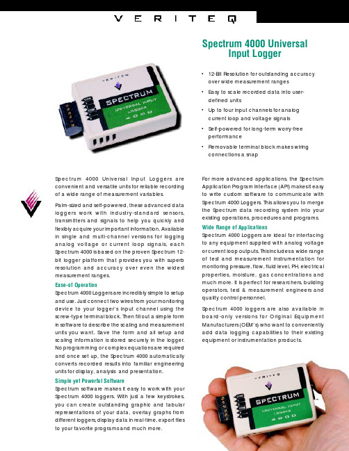
•12-Bit Resolution for outstanding accuracy over wide measurement ranges •Easy to scale recorded data into user-defined units •Up to four input channels for analog current loop and voltage signals •Self-powered for long-term worry-free performance •Removable terminal block makes wiring connections a snap Spectrum 4000 Universal Input Logger Spectrum 4000 Universal Input Loggers are convenient and versatile units for reliable recording of a wide range of measurement variables.Palm-sized and self-powered, these advanced data loggers work with industry-standard sensors,transmitters and signals to help you quickly and flexibly acquire your important information. Available in single and multi-channel versions for logging analog voltage or current loop signals, each Spectrum 4000 is based on the proven Spectrum 12-bit logger platform that provides you with superb resolution and accuracy over even the widest measurement ranges.Ease-of OperationSpectrum 4000 Loggers are incredibly simple to setup and use. Just connect two wires from your monitoring device to your logger’s input channel using the screw-type terminal block. Then fill out a simple form in software to describe the scaling and measurement units you want. Save the form and all setup and scaling information is stored securely in the logger.No programming or complex equations are required and once set up, the Spectrum 4000 automatically converts recorded results into familiar engineering units for display, analysis and presentation.Simple yet Powerful SoftwareSpectrum software makes it easy to work with your Spectrum 4000 loggers. With just a few keystrokes,you can create outstanding graphic and tabular representations of your data, overlay graphs from different loggers, display data in real-time, export files to your favorite programs and much more.For more advanced applications, the Spectrum Application Program Interface (API) makes it easy to write custom software to communicate with Spectrum 4000 Loggers. This allows you to merge the Spectrum data recording system into your existing operations, procedures and programs.Wide Range of Applications Spectrum 4000 Loggers are ideal for interfacing to any equipment supplied with analog voltage or current loop outputs. This includes a wide range of test and measurement instrumentation for monitoring pressure, flow, fluid level, PH, electrical properties, moisture, gas concentrations and much more. It is perfect for researchers, building operators, test & measurement engineers and quality control personnel.Spectrum 4000 loggers are also available in board-only versions for Original Equipment Manufacturers (OEM’s) who want to conveniently add data logging capabilities to their existing equipment or instrumentation products.。
API 4000 技术参数

一、产品介绍
SCIEX公司液质联用仪, 高稳定可靠性、高灵敏度,4000型特别设计了TurboV 离子源,系统采用最新科技发展的成果,进行革新性的设计,具有无可比拟的灵敏度、选择性、重现性,提供更稳定、更可靠的结果。
二、仪器配置
主机
离子源
工作站
三、技术参数:
API离子源
配置高效率“V型Turbo电离源”及TurbolonSpray和APCI两种离子源探针即插即用(plug-and-play)
离子光学和四极杆质量分析器
专利碰撞聚焦四极杆Q0保证离子的最大传输率
专利线性加速碰撞LINAC技术可消除记忆效应,提高灵敏度
检测系统
脉冲计数检测器可快速进行正/负离子检测方式切换
动态范围:1—4E6cps
真空系统
两级涡轮分子泵,空气冷却,无需维护
断电后自动关闭系统
数据处理和控制系统
定性和定量分析功能
可自动进行数据实时和后处理
安装要求
体积:52*50*130cm (H*D*L)
运行环境:15-30℃
电源:208-240V
气体:高纯氮气,零级空气(无油、清洁压缩空气)
四、相关二手产品图片
五、二手产品信息
商品名称:二手API 4000 三重四极杆质谱仪器种类:质谱
价格:80万
年限:1年内
仪器状态:无故障正常运行
仪器发布:仪器无忧网/司马缸APP
仪器来源:企业。
(译稿)TS4000有毒气体探测器使用说书

氯
氯化氢
二氧化硫
化 提供气体 指示值 提供气体 指示值
氢 100ppm 100ppm 100ppm 35ppm
氧
氧化氮
硫化氢
二氧化氮
化 提供气体 指示值 提供气体 指示值 提供气体 指示值
氮 100ppm 100ppm 100ppm 35ppm 100ppm 25ppm
二 二氧化氮
氯
氧 提供气体 指示值 提供气体 指示值
3.6
3.1 打开设备包装 所有由 GM 装运的设备被包装在防震箱,防震箱保护设备受到
物理性的破坏。包装物品应小心地取下来并根据包装箱内的清单核对
一下。如果发生任何损坏和零乱,请与 GM 联系。查阅 8.0 节可见联 系信息。
提示:每一个 TS4000 在 GM 工厂已完整地测试过,但是,每个电化 学传感器必须安装并进行标定,然后在启动前进行完整的核对以保证
GeLin Tong
Model TS4000
智能型毒性气体探测器
使用说明书(译稿)
Rev.1
无锡格林通安全装备有限公司 地址:无锡市湖滨路 157 号 C 区 11 号 电话:0510-85122222、85110111 传真:0510-85128222 邮编:214073
E-mail:sales@
4
5.9.15 通讯 2 数据格式(0×0014) 5.9.16 复位继电器(0×0016) 5.9.17 传感器寿命(0×0017) 5.9.18 传感器 scale(0×0018) 5.9.19 传感器型号(0×0019) 5.9.20 总的接收错误(0×0020) 5.9.21 总的数据错误(0×0021) 5.9.22 功能代码错误(0×0022) 5.9.23 起始地址错误(0×0023) 5.9.24 CRC 高字节错误(0×0025) 5.9.25 CRC 低字节错误(0×0026) 5.9.26 清除通讯错误(0×002D) 5.9.27 清除界面模块通讯错误(0×002E) 6.0 维修与保养 6.1 维修总述 6.2 存贮 7.0 故障分析 7.1 故障代码及解决办法
ARTISAN技术集团-OHP4000系列数字保持音频系统用户手册说明书

User ManualOn-Hold Plus 4000/4500 Digital On-Hold Audio SystemBefore using this unit, please read these operating instructions carefully.Afterwards, keep them handy for future reference.OHP 4000 Series User ManualMessageStudio Software - allows user to create fully customized on-hold audiocontent on a PC and record directly into OHP 4000's digital memory.Digital flash memory - design retains music/message content even during powerloss...unit ships with preloaded audio.LCD Control Panel - displays program length, time remaining in unit's memory, andunit's status.Trigger switch - unit can be triggered to start program content from the beginningwith an external trigger switch.Analog Phone Adapter Module (OHP4500 Only) - adds music-on-hold capabilityto most standard analog and KSU-less telephones with up to 4 lines and 50 stationsets.External Recording Capability - audio input allows user to record from anyexternal audio source.Built-In Monitor Speaker - allows user to monitor sound with the flip of a switch.Wall Mountable - unit can play and recorde while mounted in a vertical position.3-Year WarrantyOHP 4000 Series User ManualSet-up (OHP 4000)Plug AC adapter into wall outlet.Plug AC adapter cable into jack marked "DC12V".Plug "Connector Cable A" to "AUDIO OUT" jack.Plug other end of "Connector Cable A" into phone system's music-on-hold (moh) input jack. NOTE: If the jack cannot be located, contact your phone vendor for assistance.1234Connection to PBX or KEY phone systemsPlug the supplied "T adapter" into any modular phone jack which services line 1 and 2. (This will allow you to share the phone jack with any phone extension which you have plugged in to the wall jack.)Plug the provided phone cord into the jack marked "Line 1/2" on the adapter module.Plug the other end of the phone cord into the "T" adapter which is servicing line 1 and 2.REPEAT IF LINE 3 and/or 4 ARE PRESENT123Phone ExtensionsLine 1Line 2Line 3Line 4OHP 4000 Series User ManualOHP 4000 Series User Manualused to initiate manual RECORD SPEAKER displayed when audio is Record Mode Indicator displayed when unit Playback Indicator Recording ConnectionPlayer Controls & LCD DisplayControls & FunctionsPlug "Connector Cable B" into "speaker out" or "audio out" jack of your computer's sound card or connect to the "headphone" jack of your PC's speakers (if available).NOTE: If using CD or tape player for recording audio content,, connect to the headphone jackof the tape or CD player.Plug other end of "Connector Cable B" to "AUDIO IN" jack on the unit.12OHP 4000 Series User ManualOperationPlaybackPlaying Audio Stored in MemoryBy default, the unit is always in "playback" mode. When unit is playing,the LCD will display a running time and the segments on the speaker iconwill move.Playback After Power LossIf power to the unit is lost, the unit will resume playback as soon as poweris reapplied. The unit retains its recorded content after power loss.RecordingAuto RecordingA special software program called MessageStudio has been included whichallows you to make your own on-hold message productions. Eachproduction made with MessageStudio will include specially encoded synctones which will automatically start and stop the recording process on theOHP 4000. These tones will not be recorded. To record from other CDs ormusic sources, see "Manual-Recording" section on the following page.Beginning Auto RecordingTo begin recording using MessageStudio software, simply press "Play Mix"button on the MessageStudio Player software screen. A start tone will beheard and the unit will begin recording automatically. When finished, ashort series of tones will signal the unit to stop recording. After recording,the unit automatically returns to active play mode.NOTE: During recording, the LCD will display a moving arrow from the CDicon to the memory chip icon. You will hear what is being recordedthrough the built-in preview speaker. When recording is finished, thecounter on the LCD will display a running playback time.IMPORTANT: To avoid inadvertent erasure of stored audio program,remove "Connector Cable B" from the OHP 4000's "AUDIO IN" jack whenrecording is finished.OHP 4000 Series User ManualImpedance SwitchLocation -- right side of unitOperation -- Most telephone systems prefer an 8 ohm output. Ifyou are working with an older phone system, the 600 ohm settingmay be preferable.Speaker ButtonLocation -- left top, located below the "REC" buttonOperation -- Push "SPEAKER" button to listen to program playing fromdigital memory. Push "SPEAKER" button again to turn off speaker.Audio being recorded plays through speaker, regardless of speaker switchposition. Speaker switch position has no effect on "AUDIO OUT" playback.Volume ControlLocation -- rear panelOperation -- controls output level of "AUDIO OUT" jack. To adjust, turncontrol knob clockwise to increase volume. Set proper volume level bycalling in from a phone close to the unit (or cell phone) and having yourcall placed on hold.Power SwitchLocation -- rear panelOperation -- turns power on or off. When power is on, LCD is illuminated.OHP 4000 Series User ManualOther FunctionsRemote TriggerLocation -- rear panelConnection -- 2.5 mm mini jackOperation -- By connecting a momentary switch to this jack, theunit will play audio content from memory when triggered.Content will play through once and then reset, ready for nexttrigger sequence.Audio InLocation -- rear panel next to "TRIGGER" jackConnection -- 3.5 mm mini jackOperation -- Connect audio cable from the "LINE OUT" or"headphone out" jack of any external audio source to the "AUDIOIN" jack.Adding Additional MemoryConfigurationThe OHP 4000 comes standard with 8 minutes of flash memory.Memory can be expanded to 16, 24 or 32 minutes by addingmemory modules in 8-minute increments. Memory modules can beplaced into 3 available memory expansion slots located on thecircuit board. The memory slots can be accessed by removing thethe 5 screws on the bottom of the unit and then lifting awaybottom portion of the housing.Installation1. Turn power switch to OFF position and disconnect all cords andcables from the unit.2. Remove five screws in bottom of unit.3. Remove lower portion of the case housing.4. Carefully insert the 24-pin memory module chip in the openexpansion slot (next to the existing chip).5. Reconnect cords and cables.6. Turn power switch to ON position.OHP 4000 Series User ManualMessageStudio TMPlayer Softwarefiles from the MessageStudio CD-ROM(choose from 20 music selections)message files from the MessageStudio CD-ROM or...add a custom message about your company!Choose the time interval between messagesView the length of your final productionRecord a message in your own voiceLaunch the MessageStudio Writer SoftwareMessageStudio Player Main WindowUsing MessageStudio software, creating professional sounding custom on-hold audio is simple, quick and easy. PC with a 486 or better processor and a 16-bit sound card.new on-hold message productions any time you wish. You may record new messages in your own voice (using a mic hooked up to your PC sound card) or have messages professionally produced by On-Hold Plus or any other professional voice talent (see MessageStudio Writer on the following page). When your production is finished, you will record it into the digital flash memory in your OHP 4000. For details on recording into the OHP 4000, see the "Auto Recording" section in this manual.MessageStudio works with any .WAV or .MP3 audio files. There are 20 different music files as well as a choice of professionally voiced "thanks for holding..." messages included with the MessageStudio software.Recording Messages in Your Own VoiceUsing the MessageStudio Player Software and a mic hooked up to your PC's sound card, you can record professional sounding messages in your own voice. To record, click the "RECORD MSG" button in the MessageStudio Player window.NOTE: Confirm that your "MICROPHONE" is selected as a recording input in your sound card controls and that the volume is turned up.Creating Custom On-Hold AudioOHP 4000 Series User ManualCreating an On-Hold Audio ScriptTo assist you in writing your on-hold audio script, the MessageStudiosoftware includes a fun and easy scriptwriting utility called MessageStudioWriter. This utility may be accessed from the main screen of the software byclicking on the "Write Msg." button (located at the bottom right of thescreen). Even if you’re not a Madison Avenue copywriter, you’ll find theprocess quick, easy and fun. Just by asking a few questions, the intuitivesoftware will create several choices of beginning and ending sentences foryou. Simply click on your choices, add a sentence or two of your own, andyou’re done...it’s that easy.Your finished script can either be read by you or submitted to On-HoldPlus for professional voice-over of your custom messages.MessageStudio Writer Main WindowProfessional Production Services from On-Hold PlusOn-Hold Plus offers complete, professional production services featuring"national broadcast quality voice talent". Your finished on-hold messages(four 30-second message segments) can be e-mailed or sent to you on a CD-ROM. Your messages will be sent to you within 3 to 5 working days (e-maildelivery) or 10 to 15 days (CD-ROM delivery) from receipt of your script.Using the MessageStudio Player, you will add these professionally voicedmessage files to the program for playback with your choice of backgroundmusic.To submit your production to On-Hold Plus for professional production, justfollow the step-by-step instructions in the MessageStudio Writer software.OHP 4000 Series User ManualWarrantyLimited WarrantyOn-Hold Plus warrants this product to be free from manufacturing defects in materialand workmanship under normal use and conditions for a period of 3 years from date oforiginal purchase in the United States.Should service be necessary under this warranty for any reason due to manufacturingdefect during this 3-year period from date of original purchase, On-Hold Plus will eitherrepair the unit or replace it with a reconditioned unit at no charge.You may return the unit to On-Hold Plus at the address listed below.• Pack the unit in a well-padded, heavy, corrugated box.• Enclose proof of purchase.• Enclose your check or money order payable to On-Hold Plus in the amount of $10.00to cover shipping and handling costs.• Ship the unit prepaid via UPS or parcel post (insured).Note: This warranty is void if the product is:(a) Damaged through negligence, misuse, abuse, or accident.(b) Modified in any way.(c) Damaged because it is improperly connected to the equipment of othermanufacturers.This warranty does not cover:(a) Damage to equipment not properly connected to the product.(b) Costs incurred in the shipping of the product to On-Hold Plus.(c) Damage or improper operation of unit caused by customer abuse, misuse, negligence,or failure to follow operating instructions provided with the product.(d) Ordinary adjustments to the product which can be performed by customer asoutlined in the owner's manual.(e) Damage to compact discs.THIS WARRANTY IS NON-TRANSFERABLE AND APPLIES ONLY TO THE ORIGINALPURCHASER AND DOES NOT EXTEND TO SUBSEQUENT OWNERS OF THE PRODUCT. ANYAPPLICABLE IMPLIED WARRANTIES, INCLUDING THE WARRANTY OF MERCHANTABILITYARE LIMITED IN DURATION TO A PERIOD OF THE EXPRESS WARRANTY AS PROVIDEDHEREIN BEGINNING WITH THE DATE OF ORIGINAL PURCHASE AT RETAIL AND NOWARRANTIES, WHETHER EXPRESS OR IMPLIED, SHALL APPLY TO THIS PRODUCTTHEREAFTER. On-Hold Plus MAKES NO WARRANTY AS TO THE FITNESS OF THE PRODUCTFOR ANY PARTICULAR PURPOSE OR USE.UNDER NO CIRCUMSTANCES SHALL On-Hold Plus BE LIABLE FOR ANY LOSS, DIRECT,INDIRECT, INCIDENTAL, SPECIAL, OR CONSEQUENTIAL DAMAGE ARISING OUT OF OR INCONNECTION WITH THE USE OF THIS PRODUCT.THIS WARRANTY IS VALID ONLY IN THE UNITED STATES OF AMERICA. THIS WARRANTYGIVES YOU SPECIFIC LEGAL RIGHTS. HOWEVER, YOU MAY HAVE OTHER RIGHTS WHICHMAY VARY FROM STATE TO STATE. SOME STATES DO NOT ALLOW LIMITATION ONIMPLIED WARRANTIES OR EXCLUSION OF CONSEQUENTIAL DAMAGE. THEREFORE THESERESTRICTIONS MAY NOT APPLY TO YOU.On-Hold Plus and MessageStudio are registered trademarks of IntelliTouch Communications. © IntelliTouch Communications. All rights reserved.No part of this document may be photocopied, reproduced, or translated into another language without the prior written consent of IntelliTouch Communications. FCC Information This equipment has been tested and found to comply with the limits for a Class B digital device, pursuant to Part 15 of the FCC Rules. These limits are designed to provide reasonable protection against harmful interference in a residential installation. This equipment generates, uses, and can radiate radio frequency energy and, if not installed and used in accordance with the instructions, may cause harmful interference to radio communications. However, there is no guarantee that interference will not occur in a particular installation. If this equipment does cause harmful interference to radio or television reception, which can be determined by turning the equipment off and on, the user is encouraged to try to correct the interference by one or more of the following measures:- Reorient or relocate the receiving antenna.- Increase the separation between the equipment and receiver.- Connect the equipment into an outlet on a circuit different from that to which the receiver is connected.- Consult the dealer or an experienced radio/TV technician for help.You are cautioned that any changes or modifications not expressly approved in this manual could void your authority to operate this equipment.PrecautionsInstallationNever install the unit where it would be subjected to:- heat sources such as radiators or air ducts.- direct sunlight.- excessive dust.- moisture or rain.- mechanical vibration or shock.- unleveled surface.• When the unit is used with an AC power adapter, do not wrap the unit in a cloth, blanket, etc. If you do so,the temperature inside and outside the unit may rise considerably, resulting in malfunctioning of the unitor serious accidents.• If the unit is brought directly from a cold to a warm location, or is placed in a very damp room, moisture maycondense on the lens inside the unit. Should this occur, the unit will not operate. In this case, remove thedisc and leave the unit in a warm place for several hours until the moisture evaporates.• For the unit to operate at its best, it should not be subjected to temperatures below 5˚C (41˚F) or above 35˚C(95˚F).Warnings • Before operating the unit, please read this manual thoroughly and retain it for future reference.• To prevent fire or shock ha zard, do not expose the unit to rain or moisture. To avoid electrical shock, do notopen the cabinet. Refer servicing to qualified personnel only.• The use of optical instruments with this product will increase eye hazard.Care & MaintenanceCleaning -- Do not use volatile chemicals on this unit. Clean by lightly wiping with a soft cloth.Customer SupportToll-free customer support is available from 8AM to 5PM (PST) Monday thru Friday by calling 800-839-7277Information。
FOX4000型电子鼻研究透明塑料母粒气味

理 和人 类 嗅觉 完 全 类 似 。传感 器 阵列 系统 不 是
单 独 的分析 部分 气 味信 息 , 而是 分析 其综 合 的整 体 信息 。基 于传 感 器 阵列技 术 和模式 识 别技术 , 电子鼻 可 以 敏感 地 识 别 气 味指 纹 及其 变 化 。 由
于 气味 的变 化通 常 与 品质 的变化 紧 密相 关 , 以 所
关 键 词 : 透 明 聚 丙 烯 成 核 剂 气 昧 F X 0 0型 电 子 鼻 O 40
S u y o m e lo a p r n a tc M a t r a c s d td nS l f Tr ns a e t Pl s i s e b t h Ba e
o n FOX4 00 Ty e El c r ni s 0 p e t o c No e
W e n iFe g
Xu Zh nm i e ng
ห้องสมุดไป่ตู้
( n gRe e rh I siu e o I Na jn s a c n t t fS NOP n z i t EC Ya g i P to h mia ., d Na jn Ja g u, 1 0 8 erc e c l Co Lt ., n ig, in s 2 0 4 )
透 明聚丙 烯 ( P 专 用 料 是 近期 新 产 品 开 发 P) 的一 个亮 点 , 这类 产 品将 促 进 P P树 脂 在 透 明包 装市 场替 代其 他 相竞 争 的材料 。我 国对 透 明 P P
的研 发起 步较 晚 , 生产 方 法 主 要是 在 P 中添加 P 透 明成核 剂 。在 透 明剂 工 艺 研 究 和 应 用 开 发 以
及高 透 明 P P产 品 种 类 和 市 场 消 费 方 面 与 国外 尚存 在较 大 的差距 , 随着 国内石 化企 业不 断加 但 大在 高透 明 P P领 域 的研 发 力 度 , 近两 年 国 内 高 透明 P P产 品的 市场应 用 已经 由原 先 的 薄膜 、 片 材 、 明水 杯 、 次 性 餐 具 等低 附加 值 的 塑 料制 透 一
沃士顿U4000系列超声传感器技术参数数据表说明书

Ultrasonic sensor UB4000-F42-E6-V1516-02-26 11:33D a t e o f i s s u e : 2016-02-26134001_e n g .x m lDimensionsElectrical ConnectionPinoutMembrane keysLED window7.552.515.55.2301053415M 12x 1806580651634A 1A 2T E A C H I NM O D ES E TStandard symbol/Connections:(version E6, pnp)Sync.Switch output 1Switch output 2Core colours in accordance with EN 60947-5-2.+ U B1- U B5234(BN)(GY)(BK)(WH)(BU)U134521 BN2 W H3 BU4 BK5 GYWire colors in accordance with EN 60947-5-2(brown)(white)(blue)(black)(gray)Additional InformationA1A2A2A1A2A1A1A2A1A3A3A2Switching output programmationObject distanceNote:means: cover transducer surface with your hand, while programming the output.If A1 = A2, the output work like A1 < A2Unusable areaprog. with A1 key prog. with A2 keyMode 1:output 1output 2Mode 2:output 1output 2Mode 3:output 1output 2A1 , A2 : Object presence detection. Both outputs operate according to the selected mode, if an object is located within the detection range.Window and Switching point:output 1output 1output 2output 216-02-26 11:33D a t e o f i s s u e : 2016-02-26134001_e n g .x m l Functional descriptionThe sensor can be completely parameterised using 2 keys on the side of the housing. One special feature of this sensor is the option of adapting the ultrasonic beam width to the ambient conditions at the place where the sensor is used.Teach-in of switching points:Teach-in of switching points is used to determine the points at which the switching outputs will change their state. In addition,the order of switching points A1 < A2, or A1 > A2 also determines the effective direction (normally closed/open function) of the window in the output function (operating mode) "Window + Switching point“ (see below).The process for Teach-in of switching point A2 is similar to what was described above, using key A2.Special feature for output function "Window + switching point“In the case of the output function (operating mode) "Window + switching point“ (see below), switching points A1 and A2 define the window limits of switch output 1.A third switching point A3 can also be defined here at which switch output 2 switches.Teach-in for switching points can only be performed within the first 5 minutes after turning on the power supply. If the switching points need to be changed at a later time, this cannot be done until there is a new Power On.Parameter assignment of the output function and ultrasound beam widthIf you press the A1 key while the power supply is being turned on and then hold it down for 1 second, the sensor goes into the two-level parameterisation of operating modes.Level 1, parametrisation of the output functionPressing the A2 key briefly will cause the possible output functions to be selected one after the other (depending on the last output function to be parameterised). The functions are indicated by a flashing sequence of the green LED.Mounting aid for FP and F42 sensors MHW 11Mounting brackets for sensorsV15-G-2M-PVCFemale cordset, M12, 5-pin, PVC cable Teach-in of switching point A1 with key A1Press key A1 > 2 seconds The sensor goes into learning mode for switching point A1Position the target object at the desired distance The sensor indicates by rapid flashing of the yellow LED that the target object has been detected. If no ob-ject is detected, the red LED flashes.Press key A1 brieflyThe sensor completes the Teach-in process for switch-ing point A1 and stores the value in permanent memo-ry. If the object is uncertain (red LED lit irregularly) the Teach-in value is not valid. Teach-in mode closes.Teach-in of switching point A3 with keys A1 and A2(only for operating mode window + switching point, see below)Press key A1 + A2 > 2 sec-ondsThe sensor goes into learning mode for switching point A3Position the target object at the desired distance The sensor indicates by rapid flashing of the yellow LEDs that the target object has been detected. If no ob-ject is detected, the red LED flashes.Press key A1 briefly(output 2: normally closed)orPress key A2 briefly(output 2: normally open)The sensor completes the Teach-in process for switch-ing point A3 and stores the value in permanent memo-ry.If the object is uncertain (red LED lit irregularly) the Teach-in value is not valid. Teach-in mode closes.16-02-26 11:33D a t e o f i s s u e : 2016-02-26134001_e n g .x m lplete and the sensor returns to normal mode. If you press the A1 key briefly instead, you go to Level 2 (parameter assignment of ultrasonic beam range).Level 2, parameter assignment of ultrasonic beam widthThe ultrasonic beam width can be adjusted to match the requirements of the application in Level 2.Pressing the A2 key briefly will cause the possible beam widths to be selected one after the other (depending on the last beam width to be parameterised). The functions are indicated by a flashing sequence of the red LED.and the sensor returns to normal mode. If you press the A1 briefly instead, you go back to Level 1 (parameter assignment of output function).If parameterisation is not complete within 5 minutes (pressing the A1 key for 2 seconds), the sensor interrupts parameterisation mode without changing the settings.SynchronisationThe sensor is equipped with a synchronisation connection to suppress mutual interaction. If it is not turned on, the sensor works at an internally generated cycle rate. Synchronisation of more than one sensor is possible in a number of different ways.External synchronisation:The sensor can be synchronised by the application of a square wave voltage externally. A synchronisation pulse on the syn-chronisation input results in the execution of a measurement cycle. The pulse width must be greater than 100 µs. The meas-urement cycle must be started with the falling signal edge. A Low level > 1 s or an open synchronisation input results in normal operation of the sensor. A High level on the synchronisation input deactivates the sensor.Two different operating modes are possible- Multiple sensors can be controlled by the same synchronisation signal. The sensors work on synonymous cycle.- Synchronisation pulses are sent cyclically to only one sensor each time. The sensors work in Multiplex mode.Self synchronisation:The synchronisation connections of up to 5 sensors with option for self-synchronisation are connected with each other. These sensors work after turning on the operating voltage in Multiplex mode. The On delay increases depending on the number of sensors to be synchronised. Synchronisation is possible during Teach-in and vice-versa. Sensors must be operated unsynchro-nised to perform Teach-in of switching points.Note:If the option for synchronisation is not used, the synchronisation input can be connected with ground (0 V) or the sensor can be operated with a V1 connection cable (4-pin).。
4000系列数字便携式分析仪使用说明书

Instruction Manual 4000 Series Digital Portable AnalyzerService Department(800) 458-6153 ext. 121(818) 882-2331 ext. 121FAX(818)341-0642E-mail:************************THIS P AGE INTENTIONALL Y LEFT BLANKTABLE OF CONTENTSSECTION TITLE PAGE1.0 Equipment DescriptionFront Panel 4Rear Panel 6Right Side Panel 7Internal components 8 2.0 Operating InstructionsSetting the Alarm 9Zeroing the Instrument 10Sampling 11 3.0 CalibrationIntroduction 12Sample Bag & Pressurized Cylinder Calibration 14Calibration Procedure 15 4.0 General MaintenanceBattery Life 16Battery Charging & Replacement 16Water loss in Refillable Sensors 18Long Term Storage 23Post Storage Startup 235.0 Troubleshooting 246.0 Warranty 257.0 Return Authorization 268.0 AppendixINTERFERING GAS DATA 27SCRUBBER INFORMATION 31Note:It is not necessary to calibrate the monitor whenreceived from the Interscan or an authorized distributor.All Interscan monitors are calibrated at the factory prior toshipment.The Interscan 4000 Digital series operates on the principle of pullinga sample (Sample draw) through a sensor. The Electrochemicalsensor is manufactured by Interscan. Electrochemical means thatit produces an electrical current proportional to the level of gaspassing through. The large size of the Interscan sensors results inlarger reactive surface area which yields greater sensitivity. Equipment Description(fig. 1)Designation FunctionLCD Display:Indicates gas level when function switch is inZERO, SAMPLE INACTIVE or SAMPLEACTIVE, and battery level when on BAT.TEST A or B.ALARM Light:LED. Flashes ON/OFF when alarm setpoint is exceeded.ALARM SET:25-Turn potentiometer with a screwdriveradjustment. Sets the alarm trip point at thedesired gas level. (low alarm set must begreater than 5% of the full scale).SPAN/CAL:25-Turn potentiometer with a screwdriveradjustment. Sets display to correspond to theconcentration of the calibration gas used forcalibrating the instrument or to the levelspecified on ECS certificate.FUNCTION SWITCH:Rotary switch as follows:OFF:Analyzer power is OFF.SAMPLEINACTIVE:Analyzer power is ON (pump is OFF),Sampling is inactive.SAMPLEACTIVE:Analyzer power and pump are on. Also in thisposition the analyzer is zeroed. Samplemeasurements and calibration areaccomplished in the sample mode.BAT.TEST A:Indicates state of charge of the Nickel-Cadmium (NiCd) batteries on the LCDDisplay. These batteries power the pump &alarm. Recharge if the LCD Display level fallsto or below 100 (ignore decimal point).BAT. TEST B:Indicates state of charge of the “C” sizealkaline batteries on the LCD Display. Thesebatteries power the main circuitry, display andare NOT re-chargeable. Replace if the LCDDisplay level falls to or below 100 (ignoredecimal point). You must allow an overnightstabilize prior to use if the batteries arereplaced. Batteries are to be checkedevery 30 days.ZERO:10-Turn Potentiometer. Allows the meter to beadjusted to zero, by compensating for anybackground signal.(fig. 2)Designation FunctionINLET:¼” O.D. Quick connect or compression gasfitting.OUTLET:¼” O.D. Quick connect or compression gasfitting.RECORDER OUTPUT:¼” phone jack for Analog recorder outputconnection. Typically 0-100mV. Tip –positive, Ring – ground.CHARGER INPUT: 3.5mm phone jack for 9V DC, 100mA chargerinput. Tip – positive, Ring – ground.SENSOR SCREWS:Used to hold Sensor or Sensor base in place.(fig. 3)AUDIBLE ALARM:Piezoelectric Horn, sounds when alarm setpoint is exceeded.The above (fig 3) page 7, #12 indicates two #1 Phillips-head screws located on the right side panel. Removing these screws allows access to the internal components. Do not remove any other screws(fig. 4)Operating InstructionsNormally, the alarm is set at the Factory at 50% of full scale. Thealarm can be reset to any desired level by following the procedurebelow. Minimum alarm level must be greater than 5% of the fullscale measuring range.Set FUNCTION switch to SAMPLE INACTIVE. Using the ZEROcontrol, advance the LCD display to the desired alarm set point.Some analyzers require the use of span tool (provided). Adjust theALARM SET (fig. 1 pg. 4)control until the alarm sounds. Adjust theZERO control slightly counterclockwise until the alarm is silent. Toconfirm setting slowly adjust the ZERO control clockwise until thealarm sounds. Re-adjust the ALARM SET control if necessary.Adjust the ZERO control for a reading of “0” on the display.The Analyzer must always be zeroed, prior to use.Zero adjustments must be made in the SAMPLE ACTIVE mode,i.e. with the pump on, in air free of interfering gases. If necessary,use zero air or a C-12 filter (provided) to zero in the sampling area.When using C-12 zero filter, connect externally to gas inlet. Allowreading to stabilize, before making final zero adjustment,(stabilization can take approximately 20 minutes). The C-12 filtermust be removed after zeroing the analyzer.Analyzer must be zeroed prior to sampling (section 2.1).Set the FUNCTION switch to SAMPLE ACTIVE to activate the pump. If the INLET or OUTLET is blocked, the pump may stall. Note: Running the Analyzer with blocked INLET or OUTLET may lead to the sensor leaking caustic electrolyte leading toanalyzer damage.Power analyzer off, and clear the blockage. To reset the pump, set the FUNCTION switch to SAMPLE INACTIVE momentarily and then switch again to SAMPLE ACTIVE.Nominal sample rate in MOST analyzers is approximately 1.0, ±0.2 liter per minute. NOTE: For hydrazine analyzers with the measuring range of 0-100ppb the sample flow rate is 2.2 ± 0.2 liters per minute.The Average sample run time, starting with fully charged “C” NiCd batteries, is 12 hours. If the BATTERY TEST “A” indication is down to 100 on the LCD display, the flow rate may have started to decrease. This is usually not a problem unless very precise readings are required.Sampling from high pressure may only be achieved by using the method indicated in (fig. 5).Note: The sample to the Interscan Analyzer must be drawn perpendicular to the Sample flow stream.(fig. 5)CalibrationAll analyzers are factory calibrated prior to shipment.There is no easy answer as to how often a monitor should becalibrated. This is strictly a function of the application (gasconcentration and frequency of exposure to target gas). Thepurpose for calibration is to compensate for any possible decreasein sensor sensitivity. The primary cause of sensitivity decrease isexcessive loss of water by evaporation. A secondary cause maybe by contamination from unknown sources. H2S sensors show anadditional decrease in sensitivity due to internal sulfur formation, therate of which depends on the gas concentration.Interscan’s SENSOR EXPRESS® program streamlines downtimeby sending you a pre-calibrated sensors on a regular basis per yourneeds, without the burden of returning sensors to our factory for re-certification. The sensors are shipped to you either twice , threetimes, or four times per year at your discretion.Follow the instructions received with the Sensor, allow to stabilize,and the instrument is ready for use. The factory recommendedprocedure for calibrating all INTERSCAN analyzers, involves theuse of certified calibration gas or a permeation device. Besidesbeing essential for calibration, having a known certified gasstandard on hand allows the user to test the analyzer at any time todetermine that it “really works”As indicated on the certification sheet, the Sensor Express®. It doesnot certify the analyzer as a whole. Most importantly, the SensorExpress® program is not a substitute for basic analyzermaintenance, nor does it check for malfunction of the analyzercomponents.Whatever the source of calibration gas, the recommended method is to collect the gas in the proper sample bag, which is then attached to the analyzer INLET. The calibration gas is drawn from the proper sample bag through the sensor. An exception to the use of a sample bag is for those gases, which are reactive with, or chemisorbed by the bag itself (e.g. Chlorine, Hydrazine). Teflon® or Tedlar® bags are suitable for H2S, SO2, NO and NO2. Several bag materials are suitable for CO. Contact the Factory for recommendations.The sample bag method is the factory-recommended method for calibration. Since an internal pump is used, the same flow rate conditions during the sample and the calibrate modes are assured, eliminating errors due to flow rate differences. For most applications, using a bag is the simplest procedure.A regulated pressurized certified cylinder fitted with a tee-manifold (fig. 6) and unrestricted vent is a good procedure in place of the sample bag, as long as the flow rate of the gas is at least 140 percent that of the sample pump.(fig. 6)Analyzer must be zeroed prior to calibration (sec 2.1).1. For all gases, except Chlorine or other chemisorbable types, fill the 5 litersample bag with calibration gas, and attach it to the external inlet fitting.This is best done by attaching a short length 4 inch (101.6mm) of 1/4 inch(6.35 mm) O.D. Teflon tubing to the sample bag, then inserting into theinlet fitting.2. Set the FUNCTION switch to SAMPLE ACTIVE.3. Allow 2 to 3 minutes for the reading to stabilize, and by using theSPAN/CAL control, set the display to match the calibration gas concentration being used.4. Remove the sample bag from the analyzer and allow the display tostabilize.5. The analyzer is now calibrated and set up for operation.NOTE: If you require additional information on Calibrationprocedures, please contact the Service Department at 1-800-458-******************************************General MaintenanceBecause of current requirements of the circuitry, “C” size alkalinebattery life should be check on a monthly basis, whether the unit isoperating or not. Note: Batteries vary in capacity bymanufacturer and may provide more battery life. Analyzermalfunction, as a result of low battery, will be evident as eitherinability to zero the monitor or clipping of the display at a fixedreading below full scale.Nickel-cadmium battery life is indeterminate. It is somewhatdependent upon how well the charge level is maintained.All models of the 4000 Series analyzers use two “C” size alkalinebatteries. These are located on the hinged door, right side (fig. 4 pg.8). Polarity is marked on the door over the battery holder.A few minutes warm-up/stabilization is needed before using theanalyzer if alkaline batteries are replaced before Battery Test “B”indicates a low battery condition (100). Replace “C” alkalinebatteries and allow monitor to stabilize overnight if the batteries arelow or dead. The FUNCTION switch should be set to OFF duringthis time. This is performed to allow the sensor time to stabilize.The rechargeable batteries are ½ “C” size NiCd and are rated at0.80 ampere hours. They are mounted on the hinged door, left side(fig. 4 pg. 8). Polarity is marked on the door, over the battery holder.All models use four ½ cell “C” size NiCd batteries. Condition isshown in the BATTERY TEST “A”, FUNCTION switch position. TheNiCd battery voltage changes quite rapidly as it approaches therecharge point, which makes accurate display indication difficult. Itis recommended that the batteries be recharged if the reading inBATTERY TEST “A” is at 100 (ignoring the decimal place). Allowingthe reading to drop below 100 is not recommended. Note: NiCd batteries can develop cell memory. Cell memory is caused by running the analyzer on battery power for a short period of time REPEATEDLY i.e: Running the analyzer for 20 minutes and then recharge. If this occurs repeatedly, the NiCd battery life will only retain a 20 minute charge memory.The charger is an external 9V DC, 500mA transformer and is connected to the rear of the unit prior to charging. The tip is positive and the ring ground. The FUNCTION switch should be set to OFF or SAMPLE INACTIVE when charging. The recommended charge time is 16 hours.(fig. 7)All sensors provided with a fill port require that the electrolyte matrix is maintained in a near-saturated condition in order to provide optimum performance. This is achieved by injecting distilled or deionized water into the sensor via the red plug, using the plastic syringe (provided).Refer to (fig. 7 pg. 16). Refillable sensors are identified by the red fill plug in the side of the sensor. The fill plug location may vary from(fig. 7 pg. 16). There are two types of refillable sensors. The S-type is a shorter sensor of slightly over 2 1/2 inches ( 64 mm) in height; the P-type is almost 4 inches (104 mm) in height. “P” and “S” type sensors connect to the analyzer by different connection methods.For portable survey monitors, the sensor should be removed and weighed every 1 to 2 months, depending upon usage. The weight loss is indicated on the weight label on the side of the sensor. Sensor weight is restored be removing the sensor from the analyzer and comparing the current weight of the sensor with its original weight (in grams). Sensor weight is indicated on a label located on the side of the sensor.There are three types of gas fittings used depending on the age of the original sensor and the gas being measured.(fig. 8)Male elbow ¼ O.D. tube compression fittingThis is a compression fitting comprised of the body, nut and two ferrules (fig. 8). Disconnect by loosening the nut until the tubing can be pulled away from the body. To re-attach insert the tubing and tighten the nut. Do NOT over tighten the nut as this will damage the nut and fitting(fig. 9)Quick connect male elbowThis is a quick connect system comprised of the body, o-ring and ferrule (fig. 9). Disconnect by pushing on the ring where the tubing enters the fitting and gently pulling on the tubing. Re-attach by inserting the tubing all the way in and then gently pull backward.(fig. 10)Barbed male elbowThe fitting uses a barbed connector system (fig. 10). Disconnect by pulling on the tubing. Re-attach by pushing the tubing onto the fitting until firmly seated.Fig. 11For P-type sensors refer to (fig. 11). Disconnect the 2 electrical connections to the sensor. Disconnect the tubing from each gas fitting. Loosen the screw indicated as “A”. Loosen the clamp screw “B” until the sensor can be removed from clamp.NOTE: DO NOT REMOVE ANYTHING ELSERestore the sensor to within 5 grams original sensor weight by injecting an equivalent cc of distilled or deionized water (10g. weight loss means add 10cc water). DO NOT OVERFILL. If sensor will not take on any more liquid (liquid starts coming out the fill port) do not attempt to add additional distilled water.Note: Weight loss in excess per sensor weight label may prevent the restoration of the weight to within 5 grams of the original weight.DO NOT OVERFILL. After weighing and refilling replace the sensor in the analyzer, tighten screw “B” taking care only to make it tight so as to secure the sensor. Then tighten screw “A”, do not over tighten.Assure that all electrical and pneumatic fittings are secure. The sensor should be allowed to stabilize forseveral hours with power off.(fig. 12)For S-type sensors refer to (fig. 12). Disconnect the two electrical connections to the sensor. Disconnect the tubing from each gas fitting. Remove the two Sensor Screws (# 7).NOTE: DO NOT REMOVE ANYTHING ELSE!!Restore the sensor to within 5 grams original sensor weight by injecting an equivalent cc of distilled or deionized water (10g. weight loss means add 10cc water). DO NOT OVERFILL. If sensor will not take on any more liquid (liquid starts coming out the fill port) do notattempt to add additional distilled water.Note: Weight loss in excess per sensor weight label may prevent the restoration of the weight to within 5 grams of the original weight.DO NOT OVERFILL. After weighing and refilling replace the sensor in the analyzer, tighten screws on the rear of the analyzer. Assure that all electrical and pneumatic fittings are secure. The sensor should be allowed to stabilize for several hours with power off.Turn FUNCTION swit ch to “OFF” position. Disconnect charger from analyzer. Detach 15 pin “D” connector from circuit board. Remove alkaline batteries and cover analyzer to protect from dust.24 Hours Before Using:Uncover the analyzer. Install FRESH alkaline batteries. Reconnect 15-pin “D” connector from circuit board. Connect the charger to the analyzer to charge NiCd batteries.After 24 Hours:Follow instructions in Section 2.0. Analyzer is ready to use or calibrate.WarrantyINTERSCAN CORPORATION warrants portable analyzers of itsmanufacture (sensors, batteries, fuses, lamps, tubing, fittings,filters, and scrubbers excepted) to be free from defects in materialand workmanship for a period of one year from date of shipment.INTERSCAN CORPORATION warrants sensors of its manufactureto be free from defects in material and workmanship for a period ofsix months from date of shipment.INTERSCAN CORPORATION'S sole obligation under thiswarranty is limited to repairing or replacing, at its option, any itemcovered under this warranty, when such item is returned intact,prepaid to the factory (or designated service center).This warranty does not apply to any of our products which havebeen repaired or altered by unauthorized persons, or which havebeen subject to misuse, negligence, or accident, incorrect wiring byothers, installation or use not in accordance with instructionsfurnished by the manufacturer, or which have had the serialnumbers altered, effaced or removed. The sensors are factorysealed and must not be opened or modified in the field for thewarranty to remain in effect. This warranty is in lieu of all otherwarranties, whether expressed or implied.Additionally, in a custom system, warranty on any component shallnot exceed the manufacturer's warranty given to INTERSCANCORPORATION.Return AuthorizationAll returns for repairs require a "RETURN AUTHORIZATIONNUMBER" issued by the INTERSCAN Service Department uponrequest. Below is the link to the RMA form:/contact/index.phpThis is done primarily to cause the user to contact the factorydirectly. The reason for this is that a high percentage of serviceproblems are resolved over the telephone, avoiding the need forreturning the analyzer or part.Should return of the analyzer or part be advised by the ServiceDepartment, the "RETURN AUTHORIZATION NUMBER" willexpedite prompt return of the repaired unit.For service information, please contact:INTERSCAN CORPORATIONService Department(800) 458-6153 ext. 121(818) 882-2331 ext. 121FAX(818)341-0642E-mail:************************Appendix AINTERFERING GAS DATANo analytical method is completely specific. Gases present in the environment, other than the "target" gas of measurement, may affect analyzer response. Interferences are not necessarily linear, and may also exhibit time dependent characteristics.The charts that follow detail the approximate concentration in parts per million of interfering gas required to cause a 1 ppm deflection in the chosen analyzer. In many cases, specificity can be improved. Please note that the response values given are not absolute, and may vary depending on sensor formulation.The special case of how alcohols affect electrochemical sensors is discussed in this Knowledge Base article. ()For further information on the effects of interfering gases, please contact the factory.The charts follow the format, and grouping of gases, that was originally established in early Interscan print brochures.Chart 1: CO, Cl2, ClO2, H2, H2S, NO, NO2, O3, SO2 analyzersChart 2: Ethylene oxide (EtO) (C2H4O) analyzersChart 3: Formaldehyde (HCHO) analyzersChart 4: HCl, HCN, hydrazine analyzersChart 5: C2H4 (ethylene) analyzers(1) Data shown for H 2S models with ranges higher than 0-1999 ppb (2) Data shown for H 2S models with ranges of 0-1999 ppb and lower‡ = Hydrocarbons¤ = Rejection ratio can be improved electronically¶ Isopropyl alcohol represents the most significant interference on the ethylene oxide sensor, but in nearly all cases, potential problems can be overcome. Typical remedial actions include:a. Point shutdown/automatic restart, which allows the operator to temporarily interrupt monitoring at points that could be affected when isopropyl alcohol is used. Monitoring restarts automatically on a time-adjustable basis.b. Selection of monitoring points away from those areas that may be unduly affected by isopropyl alcohol.c. Using alternative germicides, which do not contain isopropyl alcohol.The EtO sensor may also respond to strong odors of colognes and perfumes, and to certain floor strippers and waxes. Refer to guidelines above covering isopropyl alcohol. Remember that you are attempting to monitor parts per million levels of ethylene oxide in an environment that may contain percent (10,000 ppm = 1 percent) levels of these potentially interfering compounds.= Negative interference= Negative interference § = Scrubber available= Negative interference= Negative interferenceAppendix B SCRUBBER INFORMATION。
VEENO ELS4000系列产品介绍

无线智能数字专业音频会议 系统。
系 统优 势
()L40 1E S0 0系 统 不 仅 提 供 卓 越 的 立 体 声 音 质 , 使 现场 人 耳 感 官 达 到 较 佳 的 立 体 感 音 效 ,并 大 大 减 少
频 率 响 应 信 噪 比/B d 屏 显 拾 音 器 拾 音 频 率
工 作 时 间
IM波段 S
全 球 公 用
2 z 2 Hz OH ~ Ok >5 9 彩 色 屏 幕 电 容 超 心形 四级 灵 敏 度 调 整 6 z 1 Hz 0H ~ 6k
内 置 电源 ( 续 2 ) 连 4h
P o u t C l cin rd c ol t e o
产品撷拾
音王音 响 HA 系列功放
由音 王 发 布 的 H 系 列 功 放 有 H 20 。 A 5 0 A A 5 0 H 3 0 体 声 、 声 道 、 接 和 桥 接 输 出 4种 模 式 ;3 双 声 道 、 单 并 () 中 功 率 功 放 , 作 在 立 体 声 、 声 道 , 接 模 式 时 带 工 单 并
中功率 和 HA 0 0大功率 , 60 可供不同需求用户选择 , 其
造 型美 观 , 计 合 理 , 全 可靠 。 A 5 0和 H 30 设 安 H 20 A 50采 用 2 U机 箱 , 用 环 形 变 压 器 供 电 , 大 提 高 了 整 机 的 采 大 安全性能 。 H 系列 功 放 特 性 : A
论 发言 ;2 E S 10系统融合功 能 :全数字无线会议 () L 4 2 讨论发言 、 发言视像 自动追踪。 V E O凭借独有 的技术优 势 。面向行业 客户 , EN 提 供安全 、 可靠 、 高质量 、 易扩展的行业解决方案 。 帮助会 议市场实现智能化管理较佳实践系统方 案 ,并不 断开
- 1、下载文档前请自行甄别文档内容的完整性,平台不提供额外的编辑、内容补充、找答案等附加服务。
- 2、"仅部分预览"的文档,不可在线预览部分如存在完整性等问题,可反馈申请退款(可完整预览的文档不适用该条件!)。
- 3、如文档侵犯您的权益,请联系客服反馈,我们会尽快为您处理(人工客服工作时间:9:00-18:30)。
4GFax 4000U服务器(通用版)用户手册无锡全真通科技有限公司尊敬的用户:您好!感谢您使用4GFax传真服务器系统,请您在使用4GFax 传真系统之前,认真阅读用户使用手册,它将帮助您在使用时,快速掌握使用技巧和方法,提高您的工作效率!目录第一章4GFax 4000U产品介绍 (4)系统概述 (5)系统要求 (6)第二章 4GFax客户端 (7)客户端安装说明 (8)客户端安装登陆 (10)客户端发送传真 (13)客户端查收传真 (16)客户端传真重发 (17)客户端联系人管理 (17)客户端帮助 (19)客户端隐藏 (19)客户端退出 (19)第三章服务端管理 (20)服务程序登陆 (20)系统配置 (21)服务监控 (22)密码修改 (22)传真查询 (23)用户与共公联系人管理 (24)部门管理 (24)用户管理 (24)公共联系人管理 (25)第四章常见问题解决 (26)联系我们 (28)第一章4GFax 4000U产品介绍4GFax 4000U硬件服务器实物图4GFax客户端界面系统概述4GFax 4000U传真服务器是基于PSTN(电话交换网)和局域网,由软件+硬件(Fax Modem或语音/传真卡)组成的新型传真服务器产品。
在企事业单位里实现只需共享一台传真服务器和传真线路,每个员工在自己电脑上通过4GFax客户端软件进行传真收发。
接收到的传真将通过4GFax传真服务器根据预设定的方式或流程自动分发到指定员工的电脑上,所有可打印的文件提交到4GFax传真服务器上自动排队发送。
4GFax特有的传真归档系统,可方便地对传真进行分类管理、查询统计。
4GFax传真编辑器,可实现传真文件的签名和加盖电子印章。
结合VPN软件(用户可选),可实现远程和移动收发传真、集团分支机构间的免费传真等,实现了传真的全程无纸化处理。
4GFax传真系统, 完全改变了传统传真机的发送方式:先打印——塞纸——拨号——发送传真,用户可以直接在电脑上提交电子文件,点击鼠标就可以将传真发送到对方传真机,发送不成功,4GFax还可以自动重发,还支持传真群发;同样,4GFax彻底改变了传统传真机的接收方式,利用4GFax接收传真再也不会有卡纸,无纸、无墨、传真机维护、泄密、地域限制等普通传真机的缺点,4GFax接收传真可以将传真自动分发到个人的传真信箱。
4GFax传真服务器为企业提供了一种智能型的传真应用解决方案,以全新的方式为用户提供快速、高效、便利的无纸化传真,其强大的管理功能,充分考虑到传真的每一个步骤。
同时为用户开放接口,可与各类办公工具、关键业务系统无缝整合,让传真的每一个过程都实现了无纸化,节省大量的传真开支,彻底改变传真收发的无序状况,大幅度提高工作效率,强有力地实行对传真的全面管理,具有传统传真机、一般传真软件难以比拟的优势。
4GFax——传真机的革命!系统要求服务器操作系统:Windows Server 2003/Windows XPMicrosoft .NET Framework Pack 2硬件:P4 / 512M / 20G以上。
应用软件:Microsoft Office 2007,Adobe Reader客户端操作系统:Windows Server 2003/Windows XPMicrosoft .NET Framework Pack 2硬件:PIII 800/ 128M / 20G以上。
第二章 4GFax客户端客户端软件操作界面功能键详细图解.客户端安装说明第一步:打开4GFax光盘,找到4GFax客户端安装程序,双击执行安装程序。
如图(图2-1)所示:图2-1点击【下一步】第二步:选择安装路径点击【更改..】选择安装路径,默认安装路径为:“C:\Program Files\4GFaxClient”点击【下一步】第三步:安装点击【安装】程序将自动安装。
第四步:完成安装并在桌面上创建4GFax传真客户端快捷方式。
客户端设置首次登陆4GFax通用版客户端系统会自动跳出4GFax服务器如下图(图3-1)所示:图3-1服务器地址设置完成之后请点击【设置】系统自动提示设置完成信息.如下图(图3-2)所示:图3-2点击【确定】系统自动提示重新启动客户端程序,程序将自动退出.如下图(图3-3)所示:图3-3客户端安装登陆在桌面上双击4GFax通用版网络传真快捷方式,启动程序.如下图(图3-4)所示:图3-4输入正确的用户帐号与用户密码,点击【确定】就可以正常登陆4GFax通用版客户端程序了.注意:1)4GFax通用版的用户帐号与用户密码均由系统管理员设置与提供.2)点击图3-4中的【设置】可以更改和设置4GFax通用版的服务器地址.3)选中记住密码系统可以自动记住最后一次登陆使用者的帐号与密码信息,省去再次输入操作.如下图(图3-5)所示:图3-54GFax通用版支持电子文件格式如下:doc、docx、xls、xlsx、ppt、pptx、jpg、jpeg、gif、pdf、bmp、tif、png、txt格式,其它格式暂不支持。
客户端发送传真添加传真件有以下两种方法:方法1:可以将鼠标指针移动到客户端面板上变成手形时双击,弹出选择文件框,选择要发送的附件.如下图(图4-1)所示:图4-1方法二:将要发送的传真附件点击拖动到4GFax客户端面板上,当文件图标变成"+"标志时放开即可.完成待发电子传真件的添加如下(图4-2)图所示:图4-2添加收件人传真机号码有以下两种方法.方法一:在中直接输入传真收件人的传真机号码.注意:每一个逗号表示逗号“,”前面所拨号码完成拨号后等待一秒,逗号的个数视具体的分机等待时间所定。
也可使用中横线“-”,每一个中横线“-”默认表示十秒(可以设置)方法二:通过4GFax客户端单击【联系人】选择添加.如下图(图4-3)所示:图4-3通过联系人管理可以管理自己的联系人与共用组的联系人。
选择需要的记录,点击【选中】就可以完成联系人的添加操作.点击4GFax传真机面板上的【发送】便完成发送操作.点击4GFax传真机面板上的【传真信箱】便可以查看到所有发送传真的发送状态.如下图(图4-4)所示:图4-4双击记录便可打开相应的传真原文件.客户端查收传真点击4GFax传真机面板上的【传真信箱】选择收件箱选项卡,所有黄色记录代表收到的新传真.如下图(图5-1)所示图5-1双击每条记录就通过Microsoft Office Document Imaging可以查看传真的详细内容.如下图(图5-2)图5-2选择一条记录点击【删除】可以完成删除操作.客户端传真重发点击4GFax传真机面板上的【重发】可以方便的对已发送过的传真进行重发。
如图(图6-1)所示图6-1客户端联系人管理点击4GFax传真机面板上的【联系人】.如下图(图6-1)所示图6-1点击【管理组】可以对组进行添加、删除、修改操作.如下图(图6-2)所示图6-2在完成对组的设置之后就可以进行联系人的添加了.如下图(图6-3)所示图6-3注意:在联系人管理中,公用组是4GFax管理员添加的,每个帐号都可以显示。
其它组别均是由各个帐号独立创建,除创建帐号外都不可显示使用.客户端帮助点击4GFax传真机面板上的【帮助】便可以打开客户端相关的帮助说明文档。
客户端隐藏点击【隐藏】,将客户端隐藏到任务栏,点击任务栏中客户端图标即可恢复。
客户端退出点击【退出】,退出客户端。
第三章服务端管理服务程序登陆4GFax服务程序登陆界面如下(图4-1)所示:图4-1用户名:admin密码:admin输入正确的用户名和密码便可以进入4GFax服务程序界面如下图(图4-2)所示图4-2在4GFax服务程序界面可以方便的查看到电子传真服务现在所处的状态和传真的收发情况。
系统配置在安装服务器之后需要在4GFax服务程序中设置相关的系统参数。
点【系统设置】->【系统配置】进入4GFax 服务器的配置界面。
如下图(图4-3)所示图4-3注意:本机号是作为传真服务器对外发送传真件时在传真件上显示的发送号码。
【系统设置】->【服务监控】进入4GFax服务器服务工作状态查看界面。
如下图(图4-4)所示图4-4【系统设置】->【修改密码】进入4GFax服务器系统管理员修改密码界面。
如下图(图4-5)所示图4-4点击菜单中的传真查询菜单,可以方便按条件的查询到所有传真的收发情况.如图(图4-5)所示图4-5用户与共公联系人管理【用户管理】->【部门管理】进入4GFax服务器系统部门管理界面。
在部门管理模块中,可以方便的增加、修改、删除部门信息。
如图(图4-6)所示图4-6【用户管理】->【用户管理】进入4GFax服务器系统用户管理界面。
在用户管理模块中可以按部门查询,增加、修改、删除用户信息。
如图(图4-7)所示图4-7【用户管理】->【联系人】进入4GFax服务器系统联系人管理界面。
在联系人模块中可以为4GFax所有用户添加公共联系人。
并在客户端联系人中显示。
如图(图4-8)所示图4-8第四章常见问题解决1)4GFax传真服务程序支持的操作系统类型Windows XP/windows 2003。
2)如果对方无人接听、占线、号码故障时,系统会重新发送吗为了方便用户使用,当4GFax检测到对方无人接听、对方忙、号码故障时,首次发送传真失败后,系统会自动每隔2分钟重发一次,一共重发两次。
3)4GFax收发的传真,系统会保留多长时间永久保存,除非4GFax用户手工删除传真数据。
4)通过4GFax发送的传真会失真吗不会,4GFax系统采取了符合工业标准的编码和压缩技术,所有通过4GFax发送的电子文档是不会产生失真的。
5)发送传真时号码规则若是本地号码,请勿加区号,若有分机号,在直拨号码后面加“,,,,,,,,,,”“;”(英文分号)连接。
6)4GFax传真系统支持的附件格式以及大小doc、docx、xls、xlsx、ppt、pptx、jpg、jpeg、gif、pdf、bmp、tif、png、txt文件格式,大小在2M以内;用户发送的传真附件文件名中请勿包含两个“.”7)用4GFax发送一页A4纸大小的传真需要多长时间根据线路状况、传真文件格式、传真机类型不同,一般在1分钟以内。
8)发送传真后,传真结果显示“发送失败”的原因1.对方传真机占线;2.对方传真机无人接听;3.对方传真机人工接听,但未给传真信号或直接挂断。
大部分情况下,系统给返回给用户失败的原因,例如:BUSY、无载波信号、信号中断等等。
9)普通传真机如何发传真给4GFax用户先拨4GFax传真适配器连接的电话线路号码,听到语音提示后,再拨4GFax客户端的虚拟分机号,听到传真信号音后按“开始”按钮即可。