拾音器安装图解
EMG拾音器焊接图

EMG拾⾳器焊接图INSTALLATION INFORMATION EMG MODEL: 89WarrantyAll EMG Pickups and accessories are warranted for a period of two years. This warranty does not cover failure due to improper installation, abuse or damage. If upon examination the pickup is determined to be defective, a replacement will be made. Warranty replacement products are covered by this same warranty. This warranty covers only those pickups and accessories sold by authorized EMG Dealers. This warranty is not transferable. ? 2009 Copyright EMG INC. All Rights Reserved.PO BOX 4394 SANTA ROSA, CA 95402 USA P (707) 525-9941F (707) /doc/628763515.html0230-0114AInstallation notes:The EMG-89 has a variety of ways it can be wired into a guitar. The diagrams in this sheet are limited to the most popular because of the lack of space.The additon of the plug-on PC Board on the Push-Pull Pot adds further flexibility as you will see in the diagrams. We suggest you look fully at the installation diagrams included in this sheet along with the B157 Pickup Buss data sheet included in this package before beginning your installation.The Push-Pull pot allows you 2 options as a volume control as well as 2 other options using the pot as a tone control. If you don’t see a diagram that fits your instrument directly, or you want to do something completely different, contact our technical department and we’ll create a diagram you can follow for your installation. Certain limitations apply... When using a selection switch, refer to the included B157 Pickup Buss Instructions.SPECIFICATIONS: MODEL : 89 Single-CoilDual-CoilLogo Color Copper Magnet Type Alnico Resonant Frequency (KHz) 3.80 2.00Output Voltage (String) 1.00 2.00Output Voltage (Strum) 3.00 4.50Output Noise (60 Hz) -107 -109 Output Impedance (Kohm) 10 10Current @9V (Microamps) 160Battery Life (Hours) 1500Maximum Supply (Volts DC) 27 IMPORTANT INSTALLATION NOTES:1) Only one 9-Volt battery is required to power the pickups and any accessories such as the SPC, RPC, EXG, AB, PA-2, and Pi-2. Use an Alkaline or Lithium battery for longest life.2) The Volume Control included with the EMG System is 25K Ohm. This value is required for the system to work correctly. 3)A stereo output jack (12B) is included with the EMG Pickups; it grounds the black battery wire to turn on the pickups when the plug is inserted into the jack. If you are replacing passive pickups, make sure to use the jack included. If your guitar has a long panel jack make sure it is a stereo type, a Switchcraft 152B is recommended.4) When installing any EMG Active Pickup, DO NOT connect the bridge ground wire. This wire is usually soldered to a volume or tone control casing and goes to the bridge. This wire grounds the strings and uses them and your body as a shield against hum and buzz. It also creates a shock hazard.EMG Pickups are shielded internally and DO NOT require string grounding. This greatly reduces the possibility of reverse polarity shock from microphones and other equipment. 5) EMG Active Pickups have very little magnetism compared to passive pickups. We recommend you adjust the pickups as close to the strings as possible. Sustain and string movement will not be inhibited by close adjustment.6) If your installation is different from the diagrams in these instructions or you need additional diagrams visit our website: /doc/628763515.htmlfor a complete listing of available diagrams.7) SPECIAL NOTE:The diagrams shown are for EMG Active Pickups.All diagrams show the Red Wire coming from the pickups connected to the battery. If you are installing EMG-HZ Passive Pickups refer to their diagrams. The Red Wire of the HZ Pickup is NOT for battery power, it is a coil wire.2.751.503.083/48 MOUNTING HOLES.900.725EMG-89 (SIDE VIEW)In Dual-coil mode, coils C1 and C2 are active. In Single-coil mode, coils C2 andC3 are active.C1C2 C3General Notes:Every attempt has been made to make this a solderless installation.There are some instances where this is not possible; 1) If your instrument uses the long panel output jack and you had passive pickups you will need a new stereo output jack, the Switchcraft 152B is recommended. Soldering to the new jack will be required. 2) Some instruments may already have a battery holder installed, in that case soldering may be required.3) Instruments with two pickups may need soldering to the selection switch in some installations.Installation Instructions: EMG Model: EMG-8989 INSTRUCTIONS Page 2Using the 89 Push-Pull SwitchThe Push-Pull Switch included with the EMG-89 allows you to choose between two internal pickups of the EMG-89, single-coil and dual-coil. The Push-Pull Pot has two seperate sections: The Switch and the pot, described below.Refer to Diagrams #1 and #2The push-pull switch section (DPDT) lets you choose between thesingle-coil sound and a dual-coil sound by pulling or pushing the pot shaft up or down. You have the option of having the single-coil sound in either the up or down position and vice-versa for the dual-coil sound.Diagrams #1 and #2 show how to connect the 89 Pickup cable to choose either option. Select the diagram that suits you and push the cable connectors onto the single line 6-pin header.Simply turn over cable connectors 1 and 2 to change the wire order and this will choose between the two options. Connector 3 remains the same for either choice.Using the Pot Section as:1) A Master Volume for the Instrument or, the Pickup Volume control Refer to Diagrams #3 and #4 The pot section (25KA) can be used either as a Volume controlfor the pickup or, it can be used as the Master Volume for the guitar.Diagrams #3 and #4 show how to connect either option. Use the dual-line 10-pin header and push the cables on andinstall the shunts as needed onto the labeled headers H1 thru /doc/628763515.htmle Diagram #3 if you have a single 89 installed in your instrument,or have two or more pickups in your instrument and want to use the pot as the Volume control for the 89 Pickup only.Installing the shunts on positions H3 and H5 sends the pickup signalto the wiper of the 25K Pot, and the output of the 25K Pot is at position H1.Diagram #4 allows you to use the 25K Pot independently of the pickup output. By taking the output of the pickup from position H4, the Volume control is now available to use as a Master Volume with H1 and H2 being the input and/or output of the Volume control. H1 and H2 positions are interchangeable.Position H4, now the output of the pickup, would typically go to a selection switch or a pan-pot. Don’t forget to install theshunt on H5.Using the 89 Push-Pull Pot SectionThe Push-Pull Pot side of the EMG-89 allows you 4 different options:1) Use the pot as a Master Volume for the Instrument 2) Use the pot as a Volume control for the 89 Pickup3) Use the pot as a Master Tone control for the Instrument 4) Use the pot as a Tone control for the 89 pickupOn the PC Board there is a dual-line header with 5 pairs of pins. They are listed on the PC Board as H1 through H5. By using the the connections shown in Diagrams #3 through #6, you can choose any of the 4 options.SHUNT ON (H5)PICKUP OUTPUT (H4)MASTER VOLUME OUTPUT (H2)MASTER VOLUME INPUT (H1)PICKUP OUTPUT (H1)Diagram #4PUSH / PULL POT USED AS THE MASTER VOLUME CONTROLDiagram #1HUMBUCKING ON: DOWN POSITION SINGLE COIL ON: UP POSITIONDiagram #2SINGLE-COIL ON: DOWN POSITION HUMBUCKING ON: UP POSITIONFLIP CONNECTORS 1 AND 2AS SHOWNWIRE ORDER:WHITE GREEN BLUE YELLOW ORANGE SHIELDWIRE ORDER:GREEN WHITE YELLOW BLUE ORANGE SHIELDTO SELECTION SWITCH (VIA B157 BUSS) OR PAN-POT123123Diagram #3PUSH / PULL POT USED AS THE PICKUP VOLUME CONTROLSHUNT ON (H5)SHUNT ON (H3)OR TO THE OUTPUT JACK IN SINGLE PICKUP GUITARS WITH NO TONE CONTROLTO TONE CONTROL ORSELECTION SWITCH (VIA B157 BUSS)Diagram #8One 89 PickupOne Master Volume Control No Tone ControlDiagram #7Insert the plug onto the 7 pin header of the pickup as shown above.Note the orientation arrow.89 INSTRUCTIONS Page 3OUTPUT CABLEOUTPUTTR SBATTERY NEG (-)RED REDBATTERY BUSSOUTPUT TR SBATTERY NEG (-)OUTPUT CABLEMASTER VOLUME CONTROLVOLUME CONTROLMASTER TONE (PASSIVE)BATTERY BUSSUsing the Pot Section as:2) A Master Tone control for the instrument or, the Pickup Tone control Refer to Diagrams #5 and #6The pot section (25KA) can be used either as a Tone controlfor the pickup or it can be used as a Master Tone control for the guitar.Diagrams #5 and #6 show how to connect either option. Use the dual-line 10-pin header and push the cables on andinstall the shunts as needed onto the labeled headers H1 thru H5.Use Diagram #5 if you have a single 89 installed in your instrument,or have two or more pickups in your instrument and want to use the pot as the Tone control for the 89 Pickup only. Installing the shunt on position H3 connects a tone capacitor on the PC Board to the wiper of the 25K Pot and creates a passive Tone control the output of pickup the is at position H1.Diagram #6 uses the 25K Tone control independently of the pickup output. By taking the output of the pickup from Position H4, the control is nowavailable to use as a Master Tone with H1 and H2 being the input and/or output of the Tone control. H1 and H2 positions are interchangeable.Position H4, the output of the pickup, would typically go to a selection switch or a pan-pot.- 9V +- 9V +TO VOLUME CONTROL SELECTION SWITCH OR...Diagram #6PP POT USED AS A MASTER TONE CONTROLPICKUP OUTPUT H4INPUT TO TONE CONTROL H2OUTPUT OF TONE CONTROL H1 (ONLY IF NEEDED)PICKUP OUTPUT TO SELECTION SWITCH,EMG ACCESSORY, OR...Diagram #9One 89 Pickup One Volume One ToneREDREDFROM 89 PICKUPFROM 89 PICKUPPP POT USED AS THE PICKUP TONE CONTROLSHUNT ON H3PICKUP OUTPUT H189 INSTRUCTIONS Page 4Refer to Diagram #10 Above:1) Install the Pickups and route the cables to the control cavity keeping any excess cable under the pickup.2) Choose an up/down option from Diagram #1 or #2 and plug the 89 Pickup cable onto the push-pull pot.3) Route a coax cable from the push/pull pot (H4) to the Pickup buss, Position 1. Plug the pickup cable of the other EMG into Position 2 of the pickup buss.4) Plug a coax cable from Position 3 of the Pickup Buss to the Tone control. Plug a coax cable from the Tone control to the push/pull pot (H1)5) Plug the output cable from the push/pull pot (H2) to the output jack and push the connectors onto the T, S, and R terminals of the jack as shown.6) Plug the RED Wires of the pickups onto the V+ Supply Buss (RED Shroud) with the RED wire of the battery clip.7) Strip the insulation from the switch wires and Insert them into the GREEN and BLACK Terminal Blocks and tighten the screws with a small screwdriver. Refer to the B157 Pickup buss instructions enclosed.8) Put the battery in the insulating foam piece provided and place it securely in the control cavity.We suggest that you plug in the instrument and test it before closing the control cavity.Refer to Diagram #11 Below:1) Install the 89 Pickups and route the cables to the control cavity keeping any excess cable under the pickup.2) Choose an up/down option from Diagram #1 or #2 and plug the 89 Pickup cables onto the push-pull switch sections.3) Route a coax cable from each of the push/pull pots (H1) to the Tone controls.4) Plug a coax cable from the Bridge Tone to the Pickup Buss (Position 1) Plug a coax cable from the Neck Tone to the Pickup Buss (Position 2)5) Plug the output cable from the Pickup Buss (Position 3) to the output jack and push the connectors onto the T, S, and R terminals of the jack as shown.6) Plug the RED Wires of the pickups onto the V+ Supply Buss (RED Shroud) with the RED wire of the battery clip.7) Strip the insulation from the switch wires and Insert them into the GREEN and BLACK Terminal Blocks and tighten the screws with a small screwdriver. Refer to the B157 Pickup buss instructions enclosed.8) Put the battery in the insulating foam piece provided and place it securely in the control cavity.We suggest that you plug in the instrument and test it before closing the control cavity.MASTER TONE (PASSIVE)NECK TONEBRIDGE TONEDiagram #102 Pickups (1 EMG + 1-89)Toggle Style Select SwitchPush-Pull Pot as Master Volume with a Master Tone (Passive)FROM NECK PICKUPFROM 89-X PICKUPBATTERY NEG (-)- 9V +R SOUTPUT CABLERED REDREDGROUND BRIDGE P/UNECK P/U OUTPUT MASTER VOLUME- 9V +OUTPUTTRSBATTERY NEG (-)Diagram #112 89 Pickups2 Push-Pull Pots as Volume controls (Volumes are independent)2 Tones (Passive)Toggle Style Switch GROUND BRIDGE P/UNECK P/U OUTPUT REDREDREDOUTPUT CABLENECK VOLUMEFROM 89 PICKUP (NECK)BRIDGE VOLUMEFROM 89 PICKUP (BRIDGE)。
拾音器用户安装说明书

X.TRADIO原声级监听头用户手册前言 (2)成套监听头及配件 (3)安全注意事项 (3)简介 (4)一般连接 (5)性能指标 (10)频响及指向曲线图 (11)声学常识 (12)前言感谢阁下的信任购买X.TRADIO监听头。
本手册对此监听头作了详细介绍,为了能长期正确使用,并充分利用它的所有功能,建议您在使用前认真阅读此用户手册。
X.TRADIO监听头产品是我公司生产的以色列系列之一,外形简洁美观,投放市场以来受到广大客户的好评。
该监听头具有很好的全指向特性,可根据不同场合需要选择使用。
供电范围宽,可采用8-20V直流稳压电源供电,便于使用。
该监听头性能好、经久耐用、频响效果好、音色圆润、音调柔和。
放大器部分采用了低噪声前置放大器,性能稳定,失真小,噪声低。
其配置齐全,使用方便,而特别适合于银行大厅、看守所、审讯室、监仓、上访接待处、招标会议室等场所的录音。
成套监听头及配件您购买的监听头在出厂前经过严格的测试,包装箱是为了防止在运输过程中对监听头造成损坏。
建议您将包装箱保存好,一旦将来需要维修服务或搬运时,可以对此监听头进行防护。
纸包装箱内应包含如下附件:监听头一个用户手册一本保修卡一份监听头适配器一台(需要订购)安全注意事项不要在靠近水源的地方使用, 只能用湿布进行表面清洁。
不要向监听头喷洒液体,否则会毁坏监听头电路。
按手册指示安装监听头。
不要将监听头安装在有热源的地方,如:微波炉、电暖器、火炉、功率放大器等。
不要拆除电源的安全保护地线,确认电源不会被挤压或踩踏,尤其是电源线的两端。
尽量使用我公司提供的配件或附件。
与标准的专业音响设备配接使用,充分发挥其效能。
在安装时,确认移动连接线时不会对设备或人身造成危害。
雷电天气或长期不使用,请将此有保存好。
为专业维修人员提供详细的维修信息。
当监听头出现问题,包括:电源线损坏、液体或其他物品进入监听头内部、监听头受雨淋或受潮时、工作不正常、或从高处摔落时,请勿自行修理。
EMG拾音器焊接图

INSTALLATION INFORMATION EMG MODEL: 89WarrantyAll EMG Pickups and accessories are warranted for a period of two years. This warranty does not cover failure due to improper installation, abuse or damage. If upon examination the pickup is determined to be defective, a replacement will be made. Warranty replacement products are covered by this same warranty. This warranty covers only those pickups and accessories sold by authorized EMG Dealers. This warranty is not transferable. © 2009 Copyright EMG INC. All Rights Reserved.PO BOX 4394 SANTA ROSA, CA 95402 USA P (707) 525-9941F (707) 0230-0114AInstallation notes:The EMG-89 has a variety of ways it can be wired into a guitar. The diagrams in this sheet are limited to the most popular because of the lack of space.The additon of the plug-on PC Board on the Push-Pull Pot adds further flexibility as you will see in the diagrams. We suggest you look fully at the installation diagrams included in this sheet along with the B157 Pickup Buss data sheet included in this package before beginning your installation.The Push-Pull pot allows you 2 options as a volume control as well as 2 other options using the pot as a tone control. If you don’t see a diagram that fits your instrument directly, or you want to do something completely different, contact our technical department and we’ll create a diagram you can follow for your installation. Certain limitations apply... When using a selection switch, refer to the included B157 Pickup Buss Instructions.SPECIFICATIONS: MODEL : 89 Single-CoilDual-CoilLogo Color Copper Magnet Type Alnico Resonant Frequency (KHz) 3.80 2.00Output Voltage (String) 1.00 2.00Output Voltage (Strum) 3.00 4.50Output Noise (60 Hz) -107 -109 Output Impedance (Kohm) 10 10Current @9V (Microamps) 160Battery Life (Hours) 1500Maximum Supply (Volts DC) 27 IMPORTANT INSTALLATION NOTES:1) Only one 9-Volt battery is required to power the pickups and any accessories such as the SPC, RPC, EXG, AB, PA-2, and Pi-2. Use an Alkaline or Lithium battery for longest life.2) The Volume Control included with the EMG System is 25K Ohm. This value is required for the system to work correctly. 3) A stereo output jack (12B) is included with the EMG Pickups; it grounds the black battery wire to turn on the pickups when the plug is inserted into the jack. If you are replacing passive pickups, make sure to use the jack included. If your guitar has a long panel jack make sure it is a stereo type, a Switchcraft 152B is recommended.4) When installing any EMG Active Pickup, DO NOT connect the bridge ground wire. This wire is usually soldered to a volume or tone control casing and goes to the bridge. This wire grounds the strings and uses them and your body as a shield against hum and buzz. It also creates a shock hazard.EMG Pickups are shielded internally and DO NOT require string grounding. This greatly reduces the possibility of reverse polarity shock from microphones and other equipment. 5) EMG Active Pickups have very little magnetism compared to passive pickups. We recommend you adjust the pickups as close to the strings as possible. Sustain and string movement will not be inhibited by close adjustment.6) If your installation is different from the diagrams in these instructions or you need additional diagrams visit our website: for a complete listing of available diagrams.7) SPECIAL NOTE:The diagrams shown are for EMG Active Pickups.All diagrams show the Red Wire coming from the pickups connected to the battery. If you are installing EMG-HZ Passive Pickups refer to their diagrams. The Red Wire of the HZ Pickup is NOT for battery power, it is a coil wire.2.751.503.083/48 MOUNTING HOLES.900.725EMG-89 (SIDE VIEW)In Dual-coil mode, coils C1 and C2 are active. In Single-coil mode, coils C2 andC3 are active.C1C2C3General Notes:Every attempt has been made to make this a solderless installation.There are some instances where this is not possible; 1) If your instrument uses the long panel output jack and you had passive pickups you will need a new stereo output jack, the Switchcraft 152B is recommended. Soldering to the new jack will be required. 2) Some instruments may already have a battery holder installed, in that case soldering may be required.3) Instruments with two pickups may need soldering to the selection switch in some installations.Installation Instructions: EMG Model: EMG-8989 INSTRUCTIONS Page 2Using the 89 Push-Pull SwitchThe Push-Pull Switch included with the EMG-89 allows you to choose between two internal pickups of the EMG-89, single-coil and dual-coil. The Push-Pull Pot has two seperate sections: The Switch and the pot, described below.Refer to Diagrams #1 and #2The push-pull switch section (DPDT) lets you choose between thesingle-coil sound and a dual-coil sound by pulling or pushing the pot shaft up or down. You have the option of having the single-coil sound in either the up or down position and vice-versa for the dual-coil sound.Diagrams #1 and #2 show how to connect the 89 Pickup cable to choose either option. Select the diagram that suits you and push the cable connectors onto the single line 6-pin header.Simply turn over cable connectors 1 and 2 to change the wire order and this will choose between the two options. Connector 3 remains the same for either choice.Using the Pot Section as:1) A Master Volume for the Instrument or, the Pickup Volume control Refer to Diagrams #3 and #4The pot section (25KA) can be used either as a Volume controlfor the pickup or, it can be used as the Master Volume for the guitar.Diagrams #3 and #4 show how to connect either option. Use the dual-line 10-pin header and push the cables on andinstall the shunts as needed onto the labeled headers H1 thru e Diagram #3 if you have a single 89 installed in your instrument,or have two or more pickups in your instrument and want to use the pot as the Volume control for the 89 Pickup only.Installing the shunts on positions H3 and H5 sends the pickup signalto the wiper of the 25K Pot, and the output of the 25K Pot is at position H1.Diagram #4 allows you to use the 25K Pot independently of the pickup output. By taking the output of the pickup from position H4, the Volume control is now available to use as a Master Volume with H1 and H2 being the input and/or output of the Volume control. H1 and H2 positions are interchangeable.Position H4, now the output of the pickup, would typically go to a selection switch or a pan-pot. Don’t forget to install the shunt on H5.Using the 89 Push-Pull Pot SectionThe Push-Pull Pot side of the EMG-89 allows you 4 different options:1) Use the pot as a Master Volume for the Instrument 2) Use the pot as a Volume control for the 89 Pickup3) Use the pot as a Master Tone control for the Instrument 4) Use the pot as a Tone control for the 89 pickupOn the PC Board there is a dual-line header with 5 pairs of pins. They are listed on the PC Board as H1 through H5. By using the the connections shown in Diagrams #3 through #6, you can choose any of the 4 options.SHUNT ON (H5)PICKUP OUTPUT (H4)MASTER VOLUME OUTPUT (H2)MASTER VOLUME INPUT (H1)PICKUP OUTPUT (H1)Diagram #4PUSH / PULL POT USED AS THE MASTER VOLUME CONTROLDiagram #1HUMBUCKING ON: DOWN POSITION SINGLE COIL ON: UP POSITIONDiagram #2SINGLE-COIL ON: DOWN POSITION HUMBUCKING ON: UP POSITIONFLIP CONNECTORS 1 AND 2AS SHOWNWIRE ORDER:WHITE GREEN BLUE YELLOW ORANGE SHIELDWIRE ORDER:GREEN WHITE YELLOW BLUE ORANGE SHIELDTO SELECTION SWITCH (VIA B157 BUSS) OR PAN-POT123123Diagram #3PUSH / PULL POT USED AS THE PICKUP VOLUME CONTROLSHUNT ON (H5)SHUNT ON (H3)OR TO THE OUTPUT JACK IN SINGLE PICKUP GUITARS WITH NO TONE CONTROLTO TONE CONTROL ORSELECTION SWITCH (VIA B157 BUSS)Diagram #8One 89 PickupOne Master Volume Control No Tone ControlDiagram #7Insert the plug onto the 7 pin header of the pickup as shown above.Note the orientation arrow.89 INSTRUCTIONS Page 3OUTPUT CABLEOUTPUTTR SBATTERY NEG (-)RED REDBATTERY BUSSOUTPUT TR SBATTERY NEG (-)OUTPUT CABLEMASTER VOLUME CONTROLVOLUME CONTROLMASTER TONE (PASSIVE)BATTERY BUSSUsing the Pot Section as:2) A Master Tone control for the instrument or, the Pickup Tone control Refer to Diagrams #5 and #6The pot section (25KA) can be used either as a Tone controlfor the pickup or it can be used as a Master Tone control for the guitar.Diagrams #5 and #6 show how to connect either option. Use the dual-line 10-pin header and push the cables on andinstall the shunts as needed onto the labeled headers H1 thru H5.Use Diagram #5 if you have a single 89 installed in your instrument,or have two or more pickups in your instrument and want to use the pot as the Tone control for the 89 Pickup only.Installing the shunt on position H3 connects a tone capacitor on the PC Board to the wiper of the 25K Pot and creates a passive Tone control the output of pickup the is at position H1.Diagram #6 uses the 25K Tone control independently of the pickup output. By taking the output of the pickup from Position H4, the control is nowavailable to use as a Master Tone with H1 and H2 being the input and/or output of the Tone control. H1 and H2 positions are interchangeable.Position H4, the output of the pickup, would typically go to a selection switch or a pan-pot.- 9V +- 9V +TO VOLUME CONTROL SELECTION SWITCH OR...Diagram #6PP POT USED AS A MASTER TONE CONTROLPICKUP OUTPUT H4INPUT TO TONE CONTROL H2OUTPUT OF TONE CONTROL H1 (ONLY IF NEEDED)PICKUP OUTPUT TO SELECTION SWITCH,EMG ACCESSORY, OR...Diagram #9One 89 Pickup One Volume One ToneREDREDFROM 89 PICKUPFROM 89 PICKUPDiagram #5PP POT USED AS THE PICKUP TONE CONTROLSHUNT ON H3PICKUP OUTPUT H189 INSTRUCTIONS Page 4Refer to Diagram #10 Above:1) Install the Pickups and route the cables to the control cavity keeping any excess cable under the pickup.2) Choose an up/down option from Diagram #1 or #2 and plug the 89 Pickup cable onto the push-pull pot.3) Route a coax cable from the push/pull pot (H4) to the Pickup buss, Position 1. Plug the pickup cable of the other EMG into Position 2 of the pickup buss.4) Plug a coax cable from Position 3 of the Pickup Buss to the Tone control. Plug a coax cable from the Tone control to the push/pull pot (H1)5) Plug the output cable from the push/pull pot (H2) to the output jack and push the connectors onto the T, S, and R terminals of the jack as shown.6) Plug the RED Wires of the pickups onto the V+ Supply Buss (RED Shroud) with the RED wire of the battery clip.7) Strip the insulation from the switch wires and Insert them into the GREEN and BLACK Terminal Blocks and tighten the screws with a small screwdriver. Refer to the B157 Pickup buss instructions enclosed.8) Put the battery in the insulating foam piece provided and place it securely in the control cavity.We suggest that you plug in the instrument and test it before closing the control cavity.Refer to Diagram #11 Below:1) Install the 89 Pickups and route the cables to the control cavity keeping any excess cable under the pickup.2) Choose an up/down option from Diagram #1 or #2 and plug the 89 Pickup cables onto the push-pull switch sections.3) Route a coax cable from each of the push/pull pots (H1) to the Tone controls.4) Plug a coax cable from the Bridge Tone to the Pickup Buss (Position 1) Plug a coax cable from the Neck Tone to the Pickup Buss (Position 2)5) Plug the output cable from the Pickup Buss (Position 3) to the output jack and push the connectors onto the T, S, and R terminals of the jack as shown.6) Plug the RED Wires of the pickups onto the V+ Supply Buss (RED Shroud) with the RED wire of the battery clip.7) Strip the insulation from the switch wires and Insert them into the GREEN and BLACK Terminal Blocks and tighten the screws with a small screwdriver. Refer to the B157 Pickup buss instructions enclosed.8) Put the battery in the insulating foam piece provided and place it securely in the control cavity.We suggest that you plug in the instrument and test it before closing the control cavity.MASTER TONE (PASSIVE)NECK TONEBRIDGE TONEDiagram #102 Pickups (1 EMG + 1-89)Toggle Style Select SwitchPush-Pull Pot as Master Volume with a Master Tone (Passive)FROM NECK PICKUPFROM 89-X PICKUPBATTERY NEG (-)- 9V +OUTPUT TR SOUTPUT CABLERED REDREDGROUND BRIDGE P/UNECK P/U OUTPUT MASTER VOLUME- 9V +OUTPUTTRSBATTERY NEG (-)Diagram #112 89 Pickups2 Push-Pull Pots as Volume controls (Volumes are independent)2 Tones (Passive)Toggle Style SwitchGROUND BRIDGE P/UNECK P/U OUTPUT REDREDREDOUTPUT CABLENECK VOLUMEFROM 89 PICKUP (NECK)BRIDGE VOLUMEFROM 89 PICKUP (BRIDGE)。
舞台拾音话筒吊装解决方案—单路高配版详细资料

舞台拾音话筒吊装升降解决方案(三)能不能给观众呈现出一场场完美的表演盛宴都取决于表演者以及舞台上大大小小各种的演出辅助设备。
拾取表演者声音这块尤其重要。
像剧院、剧场、音乐厅、演播厅等专业级别高的场所对于所用的设备都是有一定专业度的要求,拥有四组预算拾音模式功能,能够随时根据不同的表演切换不同的拾音高度,无缝转场随机应变不凌乱,整体提升舞台的艺术表现力和专业力,也能为表演大大的加分,让观众赏心悦目。
适用场所:剧院、剧场、音乐厅、演播厅等需要专业辅助话筒进行吊装拾音,高度在30米内的舞台进行使用。
这款更适合舞台高度30米范围内,进行辅助话筒升降拾音使用。
为了更好的垂直吊装拾音建议采用三芯卡侬指向性不强的话筒,像心形指向、全指向或无指向性话筒。
可满足舞台现场统一控制所有机器进行不同拾音高度的升降拾音,任意切换不同的拾音高度,任意选择其中任意一台机器进行调整或者单独控制升降。
可根据现场的实际情况灵活选择安装方式,例如:平座安装或吊装在灯杆悬架上。
产地:广州品牌:桂德/TONSGOOD认证:CE认证、软著认证、实用新型专利证书产品名称:单路拾音话筒吊装器(高配版)型号:EPL-M101 适用距离范围:30M内(根据实际舞台的高度生产)功能简述:通过一条导线对麦克风在一个高度上进行随意定位.保存记忆四组高度模块.(配合控制主机使用)方案特点:1.采用日本原装进口音频线,让声音不失真,为音色、音域、音质保驾护航。
2.采用超静音电机。
3.数字化控制,精准而简便,可任意更改并保存高度,真正做到随心所欲。
4.音频线防拉遇阻停装置,能有效避免上升受阻或操作失误、机器故障强力拉断音频线的情况发生。
5.音频线防错位装置,能有效避免操作失误等情况引起的机器内部松线乱线故障。
6.拥有四个预算拾音位记忆点,四组模式任意切换,随机应变不凌乱。
7.统一控制所有机器,亦可单独控制单台机器。
产品图片控制主机资料综合介绍:功能特性1. 可用面板控制吊装器上升或下降;2. 可用遥控控制吊装器上升或下降;3. 控制主机最多可对64台吊装器分别控制或同时控制;4. 有4路保存信道,可以设置4种不同高度的模式;控制主机图片:多台吊装器连接方式:多台单点话筒吊装器控制级联,并与控制器相联吊装器#1控制主机吊装器#1吊装器#2以此类推,多台相联,即可。
拾音器的作用和安装方法

拾音器的作用和安装方法拾音器是一种用来捕捉声音的装置,它可以将声音转换成电信号,然后传输到音频设备上进行放大和处理。
拾音器在音乐演出、录音、语音识别等领域都有着重要的作用。
本文将介绍拾音器的作用和安装方法,希望能够帮助大家更好地了解和使用拾音器。
首先,我们来谈谈拾音器的作用。
拾音器主要用于捕捉声音,它可以将声音转换成电信号,然后传输到音频设备上进行放大和处理。
在音乐演出中,拾音器可以将乐器发出的声音转换成电信号,然后通过音频设备放大,使得观众可以更清晰地听到音乐的细节。
在录音过程中,拾音器可以将声音准确地捕捉下来,保证录音的质量。
在语音识别领域,拾音器可以帮助设备准确地识别和理解人类的语音,从而实现人机交互。
接下来,我们来讨论拾音器的安装方法。
首先,选择合适的拾音器对于不同的场景有着不同的要求。
在音乐演出中,常用的拾音器有动态拾音器和电容拾音器,它们分别适用于不同类型的乐器。
在录音过程中,可以根据录音的需求选择合适的拾音器,比如对于人声的录音可以选择指向性拾音器,对于乐器的录音可以选择全向性拾音器。
其次,安装拾音器时需要注意其位置和角度,这对于捕捉声音的效果有着重要的影响。
在音乐演出中,需要将拾音器放置在乐器的适当位置,并调整好角度,以保证声音的准确捕捉。
在录音过程中,需要将拾音器放置在合适的位置,避免产生噪音和回声。
最后,连接拾音器到音频设备上,调整好音量和音质,以保证声音的清晰和真实。
综上所述,拾音器在音乐演出、录音、语音识别等领域都有着重要的作用。
在使用拾音器时,需要根据不同的场景选择合适的拾音器,并注意其安装方法,以保证声音的准确捕捉和传输。
希望本文对大家了解和使用拾音器有所帮助。
电吉他E-238 E 240组装示意图
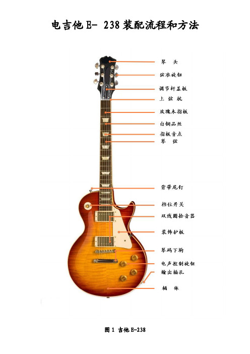
电吉他E-238装配流程和方法图1吉他E-238上图是吉他各部分和配件的名称示意图,在组装吉他之前,先要确保组装吉他的各种配件齐全,如:电子控制线路、电子后盖板、各种规格的螺丝等。
下表是电吉他E-240型号所使用的螺丝详单:序列图片规格(mm)数量名称及用途1Ø3x9.56EA弦准螺丝2Ø4.8x11.83EA调节杆盖板螺丝3Ø4.8x188EA拾音器框固定螺丝4Ø5.8x1222EA护板/插座片螺丝5Ø7.5x322EA尾钉螺丝装配吉他时,要用到的基本工具:螺丝刀、钳子、尖嘴钳,六角扳手,钢尺,焊枪、焊锡等。
图2装配步骤及方法1.装上弦枕在上弦枕底部均匀涂抹胶水,并粘在指板上弦枕的开槽处,放置10分钟,确保上弦枕与指板粘接牢固。
注意事项:要左右对齐,不可以有缝隙和两端露出指板的现象。
如图3所示:图32.装配弦准:图4如图4中所示,将弦准用螺丝刀,扳手等工具装配到琴头上,用Ø3x9.5螺丝固定,注意:将弦准在琴头上的位置摆放正再装配。
3.安装琴码下驹柱图5首先由桶身孔向电子槽内钻下驱线的通孔,再将电子线路的下驱线(即接地线)穿过洞孔,用下驹柱压住下驹线,然后用工具按压进已打好的桶身孔中,并拧上配套的螺丝调节部件,如图5中所示。
4.安装吉他电子线路将电子按图6所示,用钳子、扳手等工具将每一组音量钮和所对应的音色钮(焊接电容的为音色钮)安装在桶身上,再将3档开关扯开后,安装到图6中所示位置。
图65.安装拾音器,焊接连线①将E-238的拾音器安装在桶身上:注意拾音器要摆放正,用Ø4.8X18拾音器框螺丝固定好,安装完后如下图7:图7②焊接连线:先用焊枪将上、下拾音器的输出线分别焊接在音色钮上,然后再焊接好音量钮到3档开关的输入线,最后焊接3档开关到插座的输出线,完成后见下图8所示。
图8附图9,下面是E-238电子线路的焊接图。
焊接好后接上音箱连线检查一下声音是否正确。
拾音器头接法

一般连接与其它设备的连接COTT-C10拾音器连接线:红线:电源正极(12V直流稳压电源)蓝线:音频信号输出线(Line Out)黑线:公共地(电源负极和音频地线公共使用)拾音器安装位置的选择:拾音器可以在天花板上吸顶安装,也可以在墙面侧挂安装。
安装位置尽量离主要的谈话区域较近就可以。
比如,审讯室可以安装在被审人附近;教室可以安装在讲台附近;小型会议室可以安装在天花板中央。
拾音器连接电缆的选择和布线:该系列拾音器连接电缆的技术指标要求低,可以使用普通4芯电话线、5类网络双绞线、屏蔽/非屏蔽信号电缆等,推荐使用0.5mm2截面3芯信号电缆。
如右图所示:拾音器供电一般采用远端集中供电方式(即在音频记录设备端/扩音设备端集中供电),使用的3芯电缆中分别为电源线、音频信号线、公共地线。
电磁复杂环境可以使用屏蔽电缆,其屏蔽层单端连接设备地。
即连接拾音器一端的屏蔽网悬空,连接音频设备一端的屏蔽网接到设备地(机壳)。
注意:布线时最好单独走线,不要同交流电等强电使用同一缆槽,同时尽量远离变压器、灯具整流器等强电磁干扰设备。
电源线(红线)的连接:该系列拾音器可以使用8V-20V 宽范围直流稳压电源,推荐使用DC12V。
电源线如果大于500米,由于线损产生电压下降,推荐使用15V-20V直流稳压电源。
由于拾音器是非常灵敏的小信号放大设备,所以对电源的杂波比较敏感,务必使用杂波小的洁净优质直流稳压电源。
单个TONY-A10拾音器消耗的电流大约20毫安,也就是说一台标称值为1安培的直流稳压电源可以至少供20多个TONY-A10拾音器同时工作。
这里所指的直流稳压电源就是常说的“变压器”,一般由电源变压器、整流二极管、滤波电容及集成稳压器构成。
不能使用开关电源,它可能会给拾音器引入大量的电路杂音!什么是开关电源?简单的说:就是开关型直流稳压电源,是用电子开关管和电子开关震荡器组成的一种自动稳压电源。
比如普通台式计算机电源就是开关电源。
TRADIO拾音器用户手册

第7页
拾音器用户手册
双路混音适配器APM210 主要功能:两个拾音器的声音混合成一路后输出。
③
④
②
①
① 通道1和通道2音量调节旋钮; ② 混音输出音量调节旋钮; ③ 通道1和通道2监听耳机插孔; ④ 混音输出监听耳机插孔;
⑧ ⑦ ⑥
⑨
⑩
⑤
⑤ 六芯绿色端子,每3个接一个拾音器:V-红线、A黄线、G黑线; ⑥ 通道一、通道二、混音的音频输出端子:A-音频线、G-地线; ⑦⑩ 通道一、通道二的RCA音频输出接口,可接DVR、音视频矩阵等; ⑧⑨ 混音后的RCA音频输出接口,可以分别接两种不同的音频设备;
修改承诺
本手册的修改无需预先通知。厂商不对本文的内容作转述和承诺,特别不对商品 做暗示性承诺。本公司保留修改本指南的权利,且无须提前通知其他方而随时变更本 文。
法律承担责任
TRADIO® 系列拾音器(或称监听头)专为安防系统音视频监控配套设备所使用,不 得用于中国或其他国家法律所禁止的行为。 TRADIO® 电声产品仅供单位安防工程使 用,请个人用户勿扰。本公司不对用户使用本产品而引起的经济及法律纠纷承担任何 责任。
TRADIO中国推广
2005年,TRADIO品牌拾音器首次引入中国,以其清晰自然的高保真音质改变了以往 质次价廉的音频监控工程形象。快鱼科技公司同年获得TRADIO品牌在中国的全部知 识产权及商标。 2006年,TRADIO拾音器大量应用于全国检察院和公安局的审讯同步录音录像。 2007年,快鱼科技生产并改良的TRADIO拾音器返销国外,在欧洲市场打开局面。 2008年,首都机场T3航站楼候机大厅安装数百只原声拾音器,为奥运安保提供服务。 2009年,TRADIO获得中国安防十大创新品牌。 2010年,荣获中国安防最具影响力十大品牌、十大领先品牌、中国监所推荐品牌。 2011年,快鱼拾音器荣获中国安防十大最具竞争力品牌。 2012年,快鱼科技品牌荣获中国安防十大民族品牌,产品进入十八大主会场。
- 1、下载文档前请自行甄别文档内容的完整性,平台不提供额外的编辑、内容补充、找答案等附加服务。
- 2、"仅部分预览"的文档,不可在线预览部分如存在完整性等问题,可反馈申请退款(可完整预览的文档不适用该条件!)。
- 3、如文档侵犯您的权益,请联系客服反馈,我们会尽快为您处理(人工客服工作时间:9:00-18:30)。
拾音器安装图解
红线:电源正极(12V直流稳压电源)
蓝线:音频信号输出线(Line Out)
黑线:公共地(电源负极和音频地线公共使用)
音头连接电缆的选择和布线:
该系列拾音头连接电缆的技术指标要求低,可以使用普通4芯电话线、5类网络双绞线、屏蔽/非屏蔽信号电缆等,推荐使用0.5mm2截面3芯信号电缆。
如右图所示:拾音头供电一般采用远端集中供电方式(即在音频记录设备端/扩音设备端集中供电),使用的3芯电缆中分别为电源线、音频信号线、公共地线。
电磁复杂环境可以使用屏蔽电缆,其屏蔽层单端连接设备地。
即连接拾音头一端的屏蔽网悬空,连接音频设备一端的屏蔽网接到设备地(机壳)。
注意:布线时最好单独走线,不要同交流电等强电使用同一缆槽,同时尽量远离变压器、灯具整流器等强电磁干扰设备。
电源线(红线)的连接:
该系列拾音头可以使用 8V-20V 宽范围直流稳压电源,推荐使用DC12V。
电源线如果大于500米,由于线损产生电压下降,推荐使用15V-20V直流稳压电源。
由于拾音头是非常灵敏的小信号放大设备,所以对电源的杂波比较敏感,务必使用杂波小的洁净优质直流稳压电源。
这里所指的直流稳压电源就是常说的“变压器”,一般由电源变压器、整流二极管、滤波电容及集成稳压器构成。
不能使用开关电源,它可能会给拾音头引入大量的电路杂音!
什么是开关电源?简单的说:就是开关型直流稳压电源,是用电子开关管和电子开关震荡器组成的一种自动稳压电源。
比如普通台式计算机电源就是开关电源。
音频线的连接:
音频信号线和音频地线可以直接连接的设备:
随声听耳机、有源音箱、音响功放、音视频分配器、DVR硬盘录像机、视频服务器、调音台、录音机、声卡或其他音频设备的Line In 线性输入端(严禁接麦克风接口)。
1、硬盘录像机。
硬盘录像机大都有相应的音频输入端口,一般为同轴电缆 BNC插
头。
拾音头音频线需要连接到BNC插头的中心插针位置,拾音头公共地需要连接
到BNC插头的外壳(也就是连接同轴电缆的屏蔽铜网)
2、自带功放的有源音箱。
一整套普通的有源音箱一般都是左右两只,分别对应音
频线的左右声道。
此款拾音头只提供一路音源,所以它是“单声道”音源。
拾
音头的音频线接音箱线的左/右声道音频线,拾音头公共地接音箱线的地线。
3、其他诸如功放、调音台等音频设备的连接方法等同上述方式。
4、严禁把拾音头接入声卡、调音台、功放等设备的麦克风(MIC)输入端,否则可能
损坏设备。
这是因为拾音头内部虽然也包含麦克风,但同时也包含放大、降噪、
回声处理等电路,输出1Vpp以上的“Line Out”音频信号。
5、笔记本计算机很少配备有“Line In”音频输入插孔,一般只配备MIC 输入插
孔和SPEAKER输出插孔。
拾音头不能直接接入到 MIC口,只能购买一台专业的外
置USB接口台式声卡,使用其中的“Line In”端口来接。
注意:在所有连接过程中或拨动开关时,将您的放大设备的音量调节到最小,避免瞬间的电冲击。
地线的连接:
PEAK FIRE拾音头音频地线和电源负极合二为一,需要同时接到直流稳压电源的负极和音频设备音频输入端(Line In)的地线上。
如下图所示:
拾音头在连接时需注意哪些问题?
拾音头与其它音频放大、音频扩音或录音设备各级之间的配接较为重要。
如果连接不当不仅会影响拾音头的拾音效果,甚至会损坏拾音头及其他器材。
1.拾音头连接的基本要求:
(1)信号电平的匹配:在连接拾音头时一定要注意各器材之间的输入、输出信号电平的差异。
如果前级器材输入信号的电平过大,会产生非线性失真,反之则会降低重放系统的信噪比,甚至无法推动下一级器材的放大器,因此在配接时要注意器材之间的电平不应相差过大。
如果在实际使用中出现信号电平不适配时,必须通过衰减电路使输入的信号电平降低,或通过放大电路使输入信号的电平提升。
对于拾音头,由于其输出信号的电平达0.75~1Vpp 以上,因此可以直接送入音频设备的“Line In”端口。
(2)阻抗的匹配:如果拾音头与扬声器或其它设备连接时阻抗不匹配,会使放大器的输出功率分配不均,或因阻尼过大使声音的瞬态特性变差。
阻抗匹配的连接一般有平衡式和不
平衡式两种。
所谓平衡式是指传输信号的两芯屏蔽线对地的阻抗相等。
所谓不平衡式是指两芯屏蔽线中,其中有一根接地。
当平衡输出与不平衡输入相连接时,必须加匹配变压器进行匹配。
需要注意:拾音头的输出阻抗为600欧姆非平衡。
接插件的连接方法:拾音头与录音设备、硬盘录像机、音箱以及计算机声卡的连接是依靠各种接插件来完成的,常用的接插件有以下几种。
(1)二芯/三芯插头:主要用来传输各种器材之间的信号以及作为拾音头输入信号的输入插头。
按其直径分为有2.5mm 、3.5mm 、6.5mm 三种.,二芯插头为单声道、三芯插头为双声道。
例如:随身听耳机或电脑用的有源音箱采用的可能就是下图所示的三芯立体声插头。
左右两只耳塞或音箱,分别对应音频插头的左右声道。
此款拾音头只提供一路音源,所以它是“单声道”音源。
拾音头的音频线可以单独或同时接左/右声道,拾音头公共地接音频地。
(2)莲花插头:主要用于音频器材或视频器材之间作线路的输入和输出插头。
(3)BNC 插头:主要用视频器材之间的连接,但目前在很多品牌的硬盘录像机/卡中也用它来输入音频信号。
音频地
接监听头公共地 接监听头音频线
两种典型的硬盘录像卡
接监听头公共地 接监听头音频线
BNC
插头
外面屏蔽层接监听头公共地
中心的导线接监听头音频线
同轴电缆
连接BNC
插头的同轴电缆
一般故障的排除
一、拾音头在使用中最常遇到的问题是无声。
可用排除法确定:
1.用万用表测量拾音头端的直流电源电压,要求电压为8V-20V之间。
2. 如果您有多只拾音头,可将它们交叉配线比较, 以确定是拾音头或是连接线或是其
他配套设备的故障。
3.如果音频线接到其它音频设备,请断开连接后直接连接到随身听耳机/电脑用的普
通有源音箱进行测试。
如果声音正常说明拾音头本身没有问题,请检查连接的音频设备或其他方面。
4. 接线是否完好和可靠。
5. 放大设备的接口与拾音头是否配套。
6. 严禁把拾音头接入声卡、调音台、功放等设备的麦克风(MIC)输入端,否则可能损坏
设备。
这是因为拾音头内部虽然也包括麦克风,但同时也包含放大、降噪、回声处理等电路,其输出的为1Vpp以上的”Line Out”音频信号。
7.放大设备的音量是否调节合适。
二、拾音头有很大的噪声或品质低下。
请检查以下几方面:
1.不要使用开关电源供电,请使用12V普通直流稳压电源。
2.如果音频线接到其它音频设备,请断开连接后直接连接到随身听耳机/电脑用的普
通有源音箱进行测试。
如果噪声消失说明拾音头本身没有问题,请检查连接的音频
设备或其他方面。
3.检查是否由于声音自激造成。
监听用的音箱一定不能与拾音头靠得太近,尽量不要
在同一个房间进行测试。
由于拾音头的灵敏度高,音箱的声音反馈到拾音头的麦克
风必然会导致声音自激啸叫。
同一个房间需要监听,可以使用随身听耳机。
4.布线时最好单独走线,不要同交流电等强电使用同一缆槽,同时尽量远离变压器、
灯具整流器等强电磁干扰设备。
5.严禁把拾音头接入声卡、调音台、功放等设备的麦克风(MIC)输入端,否则可能损
坏设备。
这是因为拾音头内部虽然也包括麦克风,但同时也包含放大、降噪、回声
处理等电路,其输出的为1Vpp以上的”Line Out”音频信号。
6.有的视频监视器自带喇叭,但可能效果很差,请使用中高档耳机或有源音箱进行监
听。
1.红,电源正5 白,音频正4 黑,公共端3
2.(1)号端子:拾音头音频信号负级输出端
(2)号端子:拾音头音频信号正极输出端
(3)号端子:拾音头公共端(接黑色线)
(4)号端子:拾音头音频信号正极输入端(接白色线)
(5)号端子:拾音头电源正极输入端(接红色线)。