dgdz07-c-relay
2CDC 251 003 V0015 液位监控继电器 CM-ENS.2x 产品手册说明书

2C D C 251 003 V 0015Liquid level monitoring relay CM-ENS.2xThe CM-ENS.2x serves to regulate and control liquid levels and ratios of mixtures of conductive fluids. It can be used for overflow protection, dry running protection, filling or draining applications as well as max- and min- level alarming. Suitable electrodes are available as accessories.The device is available with two different terminal versions. You can choose between the proven screw connection technology (double-chamber cage connection terminals) and the completely tool-free Easy Connect Technology (push-in terminals).Characteristics–Devices with wide range power supply 24-240 V AC/DC –Cascadable–High EMC immunity–Adjustable response sensitivity 0.1-1000 kΩ –Control of one or two liquid levels (min/max)–Fill (UP) or Drain (DOWN), adjustable via front-face potentiometer – 3 LEDs for the indication of operational states–Screw connection technology or Easy Connect Technology available –Housing material for highest fire protection classification UL 94 V-0 –Tool-free mounting and demounting on DIN rail –22.5 mm (0.89 in) widthOrder dataType Rated control supply voltage Output contacts Connection technology Order code CM-ENS.21S 24-240 V AC/DC 1 c/o (SPDT) contactScrew connection1SVR730850R0200CM-ENS.23S 110-130 / 220-240 V AC 1SVR730850R2200CM-ENS.21P 24-240 V AC/DC Push-in connection1SVR740850R0200CM-ENS.23P110-130 / 220-240 V AC1SVR740850R22002 - Liquid level monitoring relay CM-ENS.2x | Data sheetConnection technologyMaintenance free Easy Connect Technology with push-in terminals CM-ENS.2xPApproved screw connection technology with double-chamber cage connection terminals CM-ENS.2xSPush-in terminals–Tool-free connection of rigid and flexible wires withwire end ferrule–Easy connection of flexible wires without wire endferrule by opening the terminals –No retightening necessary–One operation lever for opening both connectingterminals–For triggering the lever and disconnecting of wiresyou can use the same tool (Screwdriver according to DIN ISO 2380-1 Form A 0.8 x 4 mm (0.0315 x 0.157 in), DIN ISO 8764-1 PZ1 ø 4.5 mm (0.177 in))–Constant spring force on terminal point independentof the applied wire type, wire size or ambientconditions (e. g. vibrations or temperature changes) –Opening for testing the electrical contacting –Gas-tightDouble-chamber cage connecting terminals–Terminal spaces for different wire sizes–One screw for opening and closing of both cages –Pozidrive screws for pan- or crosshead screwdriversaccording to DIN ISO 2380-1 Form A 0.8 x 4 mm (0.0315 x 0.157 in), DIN ISO 8764-1 PZ1 ø 4.5 mm (0.177 in)Both the Easy Connect Technology with push-in terminals and screw connection technology with double-chamber cageconnection terminals have the same connection geometry as well as terminal position.2C D C 253 025 F 00112C D C 253 026 F 0011Data sheet | Liquid level monitoring relay CM-ENS.2x - 3Functions Operating controls2C D C 251 003 V 00151Adjustment of the function2 Indication of operational states with LEDsU: green LED - Status indication of control supply voltageV control supply voltage appliedR: yellow LED - Status indication of the output relaysV energizedMIN/MAX: yellow LED - Status indication of the electrodesV MIN and MAX wet W MIN wet3 Adjustment of the response sensitivity range4 Adjustment of the response sensitivity5 Marker labelApplication / Monitoring functionThe liquid level monitoring relay CM-ENS monitors and controls the liquid level and ratios of mixtures of conductivefluids. It is used for filling and draining applications, to protect pumps against dry-running, tanks against overflow and for signalization of the status of the monitored liquid level.Application exampleOperating mode with three electrodesThe CM-ENS.2x measures the electrical resistance of the liquid between two immersion electrodes and a referenceoutput relay is energized until the MAX-electrode becomes wet. Then it is de-energized and not re-energized until the MIN-electrode becomes dry. If the drain function is selected, the output relay energizes as soon as the MAX-electrode becomeswet. It remains energized until the liquid level has dropped below the MIN-electrode.Operating mode with two electrodesIf only one level should be controlled, only the MAX-electrode shall be connected at the monitoring relay (see pictureOperation with two electrodes).original state once the MAX-electrode gets in contact with the monitored medium.original state once the MAX-electrode is no longer in contact with the monitored medium.4 - Liquid level monitoring relay CM-ENS.2x | Data sheetData sheet | Liquid level monitoring relay CM-ENS.2x - 5Cascading of several devicesWith the CM-ENS.2x it is possible to use two devices in one tank. This enables, to realize a pre-warning with additional electrodes. In this way, two additional alarm outputs for exceeding or dropping below the normal level can be implemented in addition to the filling levels MAX and MIN. Also reserve pump can be connected to the additional device.Pump controlDevice ACMAXMINCMAXMINDevice BAlarmC o n t r o l p u m pAlarm, empty2C D C 252 015 F 0215Pump controlDevice ACMAXMINCMAXMINDevice BReserve pumpC o n t r o l p u m pReserve pump for filling2C D C 252 016 F 0215Fillling with alarm empty Filling with reserve pumpPump control Device ACMAXMINCMAXMINDevice BAlarmC o n t r o l p u m pAlarm, full2C D C 252 017 F 0215Pump controlDevice ACMAXMINCMAXMINDevice BReserve pumpC o n t r o l p u m pReserve pump for draining2C D C 252 018 F 0215Draining with alarm full Draining with reserve pumpElectrical connectionFunction diagramsDrain CM-ENS.xFill CM-ENS.x6 - Liquid level monitoring relay CM-ENS.2x | Data sheetTechnical dataData at T a = 25 °C and rated values, unless otherwise indicatedInput circuitType CM-ENS.2xSupply circuitRated control supply voltage U s CM-ENS.21: A1-A224-240 V AC/DCCM-ENS.23: A1-A2220-240 V ACCM-ENS.23: A3-A2110-130 V ACRated control supply voltage U s tolerance-15...+10 %Rated frequency50/60 HzFrequency range47-63 HzTypical current / power consumption24 V AC25 mA / 0.6 W110-130 V AC20 mA / 2.6 VA220-240 V AC8.5 mA / 2.1 VA24-240 V AC/DC11 mA / 2.6 VAPower failure buffering time min.20 msStart-up time t s range 0.1-1 kΩmax. 900 msrange 1-10 kΩmax. 900 msrange 10-100 kΩmax. 1.3 srange 100-1000 kΩmax. 6.3 sMeasuring circuit MAX-MIN-CSensor type electrodeMonitoring functions fill or drain, selectableMeasuring principle conductivity measurementNumber of electrodes3Response sensitivity adjustable: 0.1-1000 kΩMaximum electrode voltage 6 V ACMaximum electrode current 2 mAElectrode supply line max. cable capacity max. cable lengthrange 0.1-1 kΩ200 nF1000 mrange 1-10 kΩ200 nF1000 mrange 10-100 kΩ20 nF100 mrange 100-1000 kΩ 4 nF20 mMax. measuring cycle range 0.1-1 kΩ700 msrange 1-10 kΩ700 msrange 10-100 kΩ 1.1 srange 100-1000 kΩ 5 sUser interfaceIndication of operational statesControl supply voltage U green LEDOutput relay energized R yellow LEDElectrode / alarm status MAX/MIN yellow LEDData sheet| Liquid level monitoring relay CM-ENS.2x - 7Output circuitsKind of output11-12/14relay, 1 c/o (SPDT) contactOperating principle open- or closed-circuit principle (selectable)Contact material AgNi alloy, Cd freeRated operational voltage U e250 V ACMinimum switching voltage / Minimum switchting current12 V / 10 mAMaximum switchting voltage / Maximum switching current See ‘Load limit curves’ on page 10Rated operational current I e AC-12 (resistive) at 230 V 4 AAC-15 (inductive) at 230 V 3 ADC-12 (resistive) at 24 V 4 ADC-13 (inductive) at 24 V 2 AAC rating (UL 508)Utilization category (Control Circuit Rating Code) B 300 pilot duty; general purpose 250 V, 4 A, cos ϕ 0.75max. rated operational voltage300 V ACmax. continuous thermal current at B 300 5 Amax. making/breaking apparent power at B 3003600/360 VAMechanical lifetime10 x 106 switching cyclesElectrical lifetime AC-12, 230 V, 4 A0.1 x 106 switching cyclesMaximum fuse rating to achieve short-circuit protection n/c contact 6 A fast-acting n/o contact10 A fast-actingConventional thermal current I th 4 AGeneral dataMTBF on requestDuty time100 %Dimensions see ‘Dimensional drawings’Weight Screw connection technology Easy Connect Technology(push-in)net weight CM-ENS.210.125 kg (0.276 lb)0.117 kg (0.258 lb)CM-ENS.230.154 kg (0.340 lb)0.147 kg (0.324 lb)gross weight CM-ENS.210.150 kg (0.331 lb)0.142 kg (0.313 lb)CM-ENS.230.179 kg (0.395 lb)0.172 kg (0.379 lb) Mounting DIN rail (IEC/EN 60715), snap-on mounting without any tool Mounting position anyMinimum distance to other units CM-ENS.21: not necessaryCM-ENS.23: 10 mm if contact current > 2 AMaterial of housing UL 94 V-0 Degree of protection housing IP50terminals IP20Electrical connectionEnvironmental data8 - Liquid level monitoring relay CM-ENS.2x | Data sheetAmbient temperature ranges operation -25...+60 °C (-13...+140 °F)storage-40...+85 °C (-40...+185 °F)Damp heat, cyclic (IEC/EN 60068-2-30) 6 x 24 h cycle, 55 °C, 95 % RH Climatic class (IEC/EN 60721-3-3)3K5 (no condensation, no ice formation) Vibration, sinusoidal Class 2Shock, half-sine Class 2Isolation dataRated impulse withstand voltage U imp supply circuit / measuring circuit 4 kVsupply circuit / output circuits 4 kVmeasuring circuit / output circuits 4 kVoutput circuit 1 / output circuit 2 4 kVRated insulation voltage U i supply circuit / measuring circuit300 Vsupply circuit / output circuits300 Vmeasuring circuit / output circuits300 Voutput circuit 1 / output circuit 2300 VBasic insulation supply circuit / measuring circuit250 V AC / 300 V DCsupply circuit / output circuits250 V AC / 300 V DCmeasuring circuit / output circuits250 V AC / 300 V DCoutput circuit 1 / output circuit 2250 V AC / 300 V DCProtective separation (IEC/EN 61140, EN 50178)supply circuit / measuring circuit250 V AC / 300 V DC supply circuit / output circuits250 V AC / 300 V DC measuring circuit / output circuits250 V AC / 300 V DCPollution degree3Overvoltage category IIIStandards / DirectivesStandards IEC/EN 60947-5-1, IEC/EN 60255-27Low Voltage Directive2014/35/EUEMC Directive2014/30/EURoHS Directive2011/65/EUElectromagnetic compatibilityInterference immunity to IEC/EN 61000-6-2, IEC/EN 60255-26 electrostatic discharge IEC/EN 61000-4-2Level 3 (6 kV / 8 kV)radiated, radio-frequency,electromagnetic fieldIEC/EN 61000-4-3Level 3 (10 V/m)electrical fast transient / burst IEC/EN 61000-4-4Level 3, 2 KV / 5 kHzsurge IEC/EN 61000-4-5Level 3, installation class 3, supply circuit and measuring circuit1 kV L-L,2 kV L-earthconducted disturbances, induced byradio-frequency fieldsIEC/EN 61000-4-6Level 3, 10 Vvoltage dips, short interruptions andvoltage variationsIEC/EN 61000-4-11Class 3Interference emission IEC/EN 61000-6-3high-frequency radiated IEC/CISPR 22, EN 55022Class Bhigh-frequency conducted IEC/CISPR 22, EN 55022Class BData sheet| Liquid level monitoring relay CM-ENS.2x - 910 - Liquid level monitoring relay CM-ENS.2x | Data sheetTechnical diagrams Load limit curvesAC load (resistive)Reduction factor F for inductive AC loadDC load (resistive)Contact life time / number of operations N 220 V 50 Hz 1 AC, 360 operations/hDimensionsin mm and inchesAccessoriesin mm and incheswith DIP switchesFurther documentationDocument title Document type Document numberElectronic relays and controls Catalog2CDC 110 004 C02xxOperating and installation instructions CM-ENS Instruction manual1SVC 730 680 M0000You can find the documentation on the internet at /lowvoltage-> Automation, control and protection -> Electronic relays and controls -> Measuring and monitoring relays.CAD system filesYou can find the CAD files for CAD systems at -> Low Voltage Products & Systems -> Control Products -> Electronic Relays and Controls.Data sheet| Liquid level monitoring relay CM-ENS.2x - 11ABB STOTZ-KONTAKT GmbHP. O. Box 10 16 8069006 Heidelberg, Germany Phone: +49 (0) 6221 7 01-0Fax: +49 (0) 6221 7 01-13 25E-mail:*****************.comYou can find the address of your local sales organisation on theABB home page/contacts-> Low Voltage Products and Systems Contact usNote:We reserve the right to make technical changes or modify the contents of this document without prior notice. With regard to purchase orders, the agreed particulars shall prevail. ABB AG does not accept any responsibility whatsoever for potential errors or possible lack of information in this document.We reserve all rights in this document and in the subject matter and illustrations contained therein. Any reproduction, disclosure to third parties or utilization of its contents – in wholeor in parts – is forbidden without prior written consent of ABB AG.Copyright© 2017 ABBAll rights reserved D o c u m e n t n u m b e r 2 C D C 1 1 2 2 2 9 D 0 2 0 1 ( 0 3 / 2 0 1 7 )。
德力西电气 CDY6Z浪涌保护器产品样本2023年第1版 产品说明书

CDYN系列电涌保护器CDYNSCB系列电涌保护器专用保护装置产品样本北京办事处北区中区地址:北京市丰台区枫竹苑一区(未来假日花园)18-10 邮编:100076天津办公点地址:天津市西青区凯安道凯信佳园9-3-401邮编:300100沈阳办公点地址:辽宁省沈阳市于洪区细河南路碧桂园银河城钻石郡148-3邮编:110000长沙办公点地址:湖南长沙市芙蓉区万象企业公馆5栋2709邮编:410000郑州办公点地址:河南郑州金水区青年路145号6号楼17层1706号邮编:450000武汉办公点地址:湖北武汉市江汉区新华路186号福星国际商会大厦2516、2517室邮编:430000温州办公点地址:浙江省乐清市柳市镇德力西工业园邮编:325604成都办公点地址:成都市金牛区人民北路二段118号金牛万达广场甲级C座 16楼1603号邮编:610000南京办公点地址:江苏省南京市秦淮区洪武路23号隆盛大厦1505、1506室邮编:210000重庆办公点地址:重庆市九龙坡区渝洲路4号18-9号邮编:400039广州办事处地址:广州市荔湾区南岸路63号城启大厦1905室 邮编:510160南宁办公点地址:南宁市西乡塘区北大路中梦泽园小区岳阳阁5单元202室邮编:530003昆明办公点地址:昆明市西山区棕树营街道办事处土堆村碧鸡名城C地块9幢2802室邮编:650000贵阳办公点地址:贵阳市观山湖区石林东路中天帝景传说B区B4栋1单元1302室西安办事处地址:陕西西安市莲湖区大庆路三号蔚蓝国际A705 邮编:710082新疆办公点地址:新疆乌鲁木齐市米东区米东南路红光雅居D区6号楼3单元602室邮编:830000青岛办公点地址:青岛市城阳区正阳路177号15号楼2单元903室邮编:214000福建办公点地址:福州市晋安区东二环泰禾广场7号楼1117单元邮编:350024济南办公点地址:山东省济南市历下区工业南路55号未来城商务中心13#楼608室邮编:250000杭州办公点地址:杭州市江干区蓝桥景苑11幢2单元1002室邮编:310016南昌办公点地址:江西南昌市西湖区广场东路恒茂国际华城23幢2907邮编:330002深圳办公点地址:深圳市龙华新区民丰路1号碧水龙庭7栋4单元14D 邮编:518109兰州办公点地址:兰州市城关区瑞德摩尔万国港E座2208邮编:730020电话:153****1522合肥办公点地址:安徽省合肥市瑶海区武里山路五里山天街3A-1402室邮编:230000吉林办公点地址:吉林省长春市经开区浦东路与深圳街交汇处虹湾国际A座706室邮编:130031黑龙江办公点地址:黑龙江省哈尔滨市道外区润达国际D座2单807室邮编:150050石家庄办公点地址:石家庄市裕华区华兴生活小区41-1-102邮编:050011太原办公点地址:山西太原市万柏林区西矿街70号红星小区五单元1402邮编:030024石家庄物流地址:河北省石家庄市元氏县殷村石武铁路东国达物流园内电话:155****1257辽宁物流地址:沈阳市苏家屯区雪莲街188号(雪莲街与四环路交叉口)华翔东北亚贸城 D1 德力西陕西物流地址:陕西省西安市六村堡丰产路西段陕西商储物流园南区B1号德力西仓库山东物流地址:山东省临沂市经济技术开发区翔宇路23号华派克物流园内 重庆物流地址:重庆市江津区珞璜工业园B区重庆西部诚通物流有限公司5号库成都物流地址:四川省成都市青白江区国际集装箱物流园区德汇路9号4栋4-4号广东物流地址:广东省佛山市南海区里水镇怡和二路银裕木业制品厂直入100米河南物流地址:河南省郑州市经济开发区国际物流园喜达路宇培物流园(礼通路)东北W4-A区4B 58-59号湖北物流地址:湖北省武汉市东西湖区临空港大道23号捷利物流园3号库温州物流地址:浙江省乐清市柳市镇德力西高科技生态工业园新疆物流地址:乌鲁木齐市友谊路230号(新疆诚通国际物流园内德力西仓库)芜湖物流地址:安徽省芜湖市芜湖县新芜经济开发区朝阳路德力西物流中心产品介绍电涌保护器基础知识产品介绍技术参数SPD 常用名词解释怎样看电涌保护器的好坏?它有些什么主要技术参数,各有什么重要性?为什么电涌保护器需要后备保护装置?电涌保护器的后备保护装置需要满足那些要求?不同接地系统SPD 极数的选择Ⅰ类实验 (Class I test)用标称放电电流In 、1.2/50冲击电压和最大冲击电流Iimp 做的试验。
施耐德接触器选型样本
b TeSys D 型 3 极热过载继电器 . . . . . . . . . . . . . . . . . . . . . . . . . . . . . . . . . . . . . . 3/2 b 说明,特性. . . . . . . . . . . . . . . . . . . . . . . . . . . . . . . . . . . . . . . . . . . . . . . . . . . . . 3/3 b 型号 . . . . . . . . . . . . . . . . . . . . . . . . . . . . . . . . . . . . . . . . . . . . . . . . . . . . . . . . . . 3/5 b 附件 . . . . . . . . . . . . . . . . . . . . . . . . . . . . . . . . . . . . . . . . . . . . . . . . . . . . . . . . . . 3/9 b 尺寸,安装,线路图 . . . . . . . . . . . . . . . . . . . . . . . . . . . . . . . . . . . . . . . . . . . . 3/11
v 用于至 75 kW/400V 的电动机控制, AC-3 类别 . . . . . . . . . . . . . . . . . . . . . 1/12 v 用于至 15 kW/400V 的电动机控制, AC-3 类别 . . . . . . . . . . . . . . . . . . . . . 1/13 v 用于 25 至 200A 的电路控制, AC-1 类别 . . . . . . . . . . . . . . . . . . . . . . . . . . 1/18 b 用于电动机控制的可逆接触器, AC-3 类别 v 75 kW/400V . . . . . . . . . . . . . . . . . . . . . . . . . . . . . . . . . . . . . . . . . . . . . . . . 1/20 v 15 kW/400V . . . . . . . . . . . . . . . . . . . . . . . . . . . . . . . . . . . . . . . . . . . . . . . . 1/21 b 电源转换接触器组,用于 AC-1 负载控制 v 20 至 200 A . . . . . . . . . . . . . . . . . . . . . . . . . . . . . . . . . . . . . . . . . . . . . . . . . 1/22 b 根据所需电气寿命选型 v AC-3 使用类别 . . . . . . . . . . . . . . . . . . . . . . . . . . . . . . . . . . . . . . . . . . . . . . . 1/24 v AC-2 或 AC-4 使用类别 . . . . . . . . . . . . . . . . . . . . . . . . . . . . . . . . . . . . . . . . 1/27 v AC-1 使用类别 . . . . . . . . . . . . . . . . . . . . . . . . . . . . . . . . . . . . . . . . . . . . . . . 1/30 v DC-1 至 DC-5 使用类别 . . . . . . . . . . . . . . . . . . . . . . . . . . . . . . . . . . . . . . . . 1/32 b 可逆接触器的装配元件. . . . . . . . . . . . . . . . . . . . . . . . . . . . . . . . . . . . . . . . . . . 1/35 b 辅助模块与附件 . . . . . . . . . . . . . . . . . . . . . . . . . . . . . . . . . . . . . . . . . . . . . . . . 1/38 b D 型接触器线圈 v 交流线圈 . . . . . . . . . . . . . . . . . . . . . . . . . . . . . . . . . . . . . . . . . . . . . . . . . . . 1/45 v 直流线圈 . . . . . . . . . . . . . . . . . . . . . . . . . . . . . . . . . . . . . . . . . . . . . . . . . . . 1/48 v 宽电压范围直流线圈 . . . . . . . . . . . . . . . . . . . . . . . . . . . . . . . . . . . . . . . . . . 1/50 b 尺寸,安装与线路图 . . . . . . . . . . . . . . . . . . . . . . . . . . . . . . . . . . . . . . . . . . eSys D 型控制继电器特性 . . . . . . . . . . . . . . . . . . . . . . . . . . . . . . . . . . . . . . . . 2/2 b 用于控制电路:交流,直流或低功耗 . . . . . . . . . . . . . . . . . . . . . . . . . . . . . . . . . 2/6 b 辅助模块 . . . . . . . . . . . . . . . . . . . . . . . . . . . . . . . . . . . . . . . . . . . . . . . . . . . . . . 2/8 b 附件和备件. . . . . . . . . . . . . . . . . . . . . . . . . . . . . . . . . . . . . . . . . . . . . . . . . . . . . 2/9
CDM7塑壳

化发展的趋势 就CDW7系列智能型万能式框架断路器而言 框 架电流等级为1 000 A的抽出式产品 其外型尺寸仅为284 mm (长) 372 mm(宽) 362 mm(高) 该产品不但弥补了1 000 A电 流等级产品无框架结构的空白 其体积仅为同类框架结构产品的 二分之一 在产品外型体积为2 200 mm(高) 600 mm(宽) 800 mm(深) 成套开关柜内 采用后进 出线的方式 至少可安装4 台1 000 A产品作为系统的回路控制电源使用 框架电流等级为 3 200 A的抽出式产品 可升级提供4 000 A产品 其外型尺寸 保持3 200 A/4P产品体积不变 外型尺寸为550 mm(长) mm(宽) mm(宽) 452 mm(高) 在产品外型体积为2 200 mm(高) 471 800
研扬科技在具备了强大的技 术与行销资源能力之后 新产品 如雨后春笋 陆续贡献给业界广 大朋友 Fanless Embedded Controller之AEC 68X0系列高 端产品 在设计上不仅具有多项 专利 功用更是广泛 已经达到 世界领先水平 据悉 其中 AEC 6810已经被权威媒体 Control Engineering经过公正的客户和专家评选 评为2004年 优秀产品奖 无风扇嵌入式控制终端 AEC 68X0 系列产品 具有抗振 抗冲击能力强 温度可达 15 60 (w/CFD) 主 频可达1 GHz 并具有CF Card防振固定卡勾 铝挤型鳍片无 风扇工业系统等多项专利设计 其中AEC 6810为军工级紧 凑型工业控制终端 主要技术指标包括 抗振动能力可达5 G/ 5 500 Hz(w/CFD) 抗冲击能力可达100 G(w/CFD) 主要应 用于军工 楼宇自动化 工厂自动化等多个领域 AEC 6820 主要应用在交通 车载领域 支持 GSM/GPRS/GPS 模块 有 两个 PCMCIA 插槽 抗振动能力达到 6 G 非常适合于车载控 制终端领域 AEC 6830 主要应用于多媒体系统 内置的 MPEG2 支持 DVD 格式和基于 SPDIF 的 5.1 CH 音频 可以确 保高质量的环绕立体声 此外 还支持双显示模式 它的效果 相当于两块 VGA 卡 CLE266 北桥芯片增强了运算能力 可 选择的散热工具有效的减低了工作中的温度 可以确保在艰苦 的环境中稳定可靠的运行 AEC 6840低功耗高性能的Intel (r) ULV Celeron(r)处理器为我们提供了广泛以及可靠的应用 高传输速率的USB 2.0, 4串口和数字 I/O 通信系统 此外 一 个可选的千兆网口是它的最大优势也是工业IPC领域的一大革 新 在要求苛刻的硬件环境内仍然实现了千兆网口和视频捕捉 等强大功能 产品将广泛的应用于工业自动控制系统如工厂管 理 大楼监控以及运输等环境监测领域 研扬科技以前 现在 将来都会脚踏实地 一步一个脚印 追求创新 追求更高的品 质与服务 满足于市场与用户的需求
施耐德交流接触器施耐德接触器型号
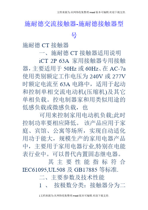
施耐德交流接触器-施耐德接触器型号施耐德CT接触器一、施耐德CT接触器适用说明iCT 2P 63A 家用接触器专用接触器,主要适用于50Hz或60Hz、在AC-7a 使用类别额定工作电压为240V或277V 时额定电流至63A电路中,适用于起动和控制单相交流电动机(压缩机)及其它单相负载。
控电制器家和用类似用途的低感负载或微感负载,也可用来控制家用电动机负载;此时控制功率要相应降低。
该产品应用于家庭、宾馆、公寓等场所,实现自动适化用功于能大,规模生产的家用电器产品中,主要用于家用电器行业,特别在电能表行业中。
可以替代内置固态继电器。
其主要性能指标符合IEC61095,UL508及GB17885等标准.二、主要参数及技术性能1 、按极数分类:接触器分为二极和四极。
2 、接触器的额定绝缘电压、约定自由空气发热电流、使用类别及其对应的额定工作电流和控制功率3、动作(操作)条件:在周围空气温度为-5℃~+63℃范围内,对接触器吸引线圈施以额定控制电源电压Us,使其发热至稳定状态时,接触器线圈在75% Us~110% Us范围内可靠吸合并工作。
其释放电压既不高于75%Us,又不低于20%Us(二极),释放电压不低于10%Us(四极)。
4 、接通和分断能力(见表2)5、机械寿命:接触器的机械寿命不小于100万次。
6、电寿命试验的接通通断,电寿命:接触器的电寿命不小于10万次。
7、接触器的使用类别为AC-1、AC-7a;8、接触器在距处,其噪声在40dB 以下。
三、主要结构及工作原理1、接触器为立体布置、双断点,触点采用银基合金、磁系统采用E型铁心,衔铁采用电工钝铁。
接触器为正装直动式双断点结构,罩盖与躯壳采用耐弧塑料制成,WCT采用自动灭弧,形成封闭灭弧室灭弧好,飞弧距离为零。
触头采用抗熔焊及耐电磨损的银基合金材料制成,导电性能好,寿命长,对环境无污染。
铁芯采用E形结构,体积小。
线圈的接线方式两接线端分别在产品的两端,接线灵活方便。
PLC交流双速电梯元件代号明系表
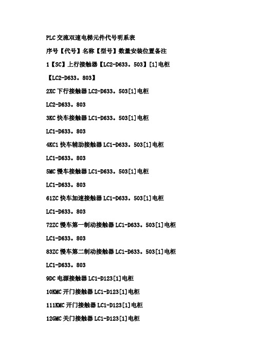
PLC交流双速电梯元件代号明系表序号【代号】名称【型号】数量安装位置备注1【SC】上行接触器【LC2-D633。
503】[1]电柜【LC2-D633。
803】2XC下行接触器LC2-D633。
503[1]电柜LC2-D633。
8033KC快车接触器LC1-D633。
503[1]电柜LC1-D633。
8034KC1快车辅助接触器LC1-D633。
503[1]电柜LC1-D633。
8035MC慢车接触器LC1-D633。
503[1]电柜LC1-D633。
80361ZC快车加速接触器LC1-D633。
503[1]电柜LC1-D633。
80372ZC慢车第一制动接触器LC1-D633。
503[1]电柜LC1-D633。
80383ZC慢车第二制动接触器LC1-D633。
503[1]电柜LC1-D633。
8039DC电源接触器LC1-D123[1]电柜10KMC开门接触器LC1-D123[1]电柜111KMC开门接触器LC1-D123[1]电柜12GMC关门接触器LC1-D123[1]电柜131GMC关门接触器、LC1-D123[1]电柜14KRJ快车热继电器、JR0-40。
60[1]电柜7.5KW。
25A15MRJ慢车热继电器JR0-40。
7。
5[1]电柜11.2KW0.25A16YJ电路安全继电器3TB4017或[1]电柜JY-16、63/110V17MSJ门连锁继电器3TB4017或[1]电柜JY-16、63/110V18M-3交流双速电动机JTD、430/560[1]机房1000/25019DZZ直流制动器、DC110V[1]曳引主机20ZLBS控制变压器[1]电柜21QX电抗器、KH01三相[1]电柜22MD直流电动机、YDJ-150[1]门机DC110V/150W或YDJ-80DC110V/80W23MD1直流电动机[同上][1]副门门机24DJR1轿顶检修插、250V。
5A单相三孔[1]顶检箱25DJR4轿顶检修插、250V。
D继电器

Dz□系列中间继电器 DZ-200系列中间继电器 JZ7系列中间继电器 JZC4系列接触器式继电器 JZC4-Z系列直流操作接触器式继电器 JZC1系列接触器式继电器 JRS1系列热过载继电器 JRS2系列热过载继电器 JRS5系列热过载继电器 JRS8系列热过载继电器 RDJ2系列热过载继电器 JR20系列热过载继电器 JR36系列热过载继电器 JS7-A系列空气式时间继电器 JS10系列数字式时间继电器 JS11S、DH11S、JSS1P1系列数显式时间继电器 JS14S、JS14SX、DH14S系列数显式时间继电器 JS14A系列时间继电器 JSS1系列数字式时间继电器 JS20系列时间继电器 DH48S系列时间继电器 JSS72系列数显式时间继电器 RDS3系列数显式时间继电器 AH3系列时间继电器 ST3P、ST3P-5P系列时间继电器 JJSB1系列数显式时间继电器 ST6P系列时间继电器 DS系列时间继电器 HH52P、53P、54P系列电磁继电器 JQX小型通用继电器 JTX-□C小型特殊用电继电器 JQX-13F(HH62P)系列电磁继电器 JT3系列直流电磁式继电器 DL、DY电流、电压继电器 JL12系列过电流延时继电器 JL14系列电流继电器 JL15系列电流继电器 JL18系列电流继电器 DX系列信号继电器 SSR系列固态继电器 JYB系列液位继电器 X J断相与相序保护继电器 BHQ系列电动机综合保护器 JD-5(B)系列电动机综合保护器 JD-5E系列电动机综合保护器 JD-6(B)系列电动机综合保护器 JD-5F系列电动机综合保护器 JD-8系列电动机综合保护器 QZ610系列电动机保护器起动器 L JM-Ⅱ漏电脉冲继电器 RDJD6系列剩余电流动作继电器 RDFL1\RDFL2系列火灾监控探测器 GUK系列路灯光控开关 KG316T系列微电脑时控开关 KG10YG系列微电脑时控开关 Kg10系列微电脑时控开关 KG16A系列微电脑时控开关 KG20L系列微电脑自动打铃仪 JDM3系列液晶计数器 SC3L系列液晶累时器 RDJX系列单相交流保护自动控制器
磁性开关SMC

缸径
D-H7型
D-H7C型
D-H7BA型
D-H7NF型
D-H7□W型
D-G5/K5型
D-G5BA型
D-G59F型
D-G5NT型
D-G5□W/K59W型
D-G39/K39型
D-G39A/K39A型
D-F7/J7型
D-J79C型
D-F79F型
D-F7BA型
D-F7BAV型
D-F7□V型
D-F7NT型
无 D-F7□W(V)型
耐热型·2色显示…………………………………………………………………P.1618 宽范围检出型 ……………………………………………………………………P.1619
南
微调电容器磁性开关 ……………………………………………………………P.1620
订制规格 …………………………………………………………………………P.1626
◆有触点磁性开关………………………………………………P.1629
一般(通用)型………………………………………………………………………P.1630 2色显示式…………………………………………………………………………P.1643 耐强磁场·2色显示式……………………………………………………………P.1646 耐热型 ……………………………………………………………………………P.1649
磁 D-A7□H/A80H型
性 D-A73C/A80C型
开 D-A79W型
关 D-A5/A6型
D-A59W型
D-A9型
D-A9□V型
D-E7□A/E80A型
D-Z7/Z8型
D-P7型
D-B3型
执行元件页码索引 (圆型数字为Best No.。)
- 1、下载文档前请自行甄别文档内容的完整性,平台不提供额外的编辑、内容补充、找答案等附加服务。
- 2、"仅部分预览"的文档,不可在线预览部分如存在完整性等问题,可反馈申请退款(可完整预览的文档不适用该条件!)。
- 3、如文档侵犯您的权益,请联系客服反馈,我们会尽快为您处理(人工客服工作时间:9:00-18:30)。
♣ 电机起动、停车(点动、连续运行、多地点 控制、顺序控制等) ♣ 电机正反转控制 ♣ 行程控制 ♣ 时间控制 ♣ 速度控制 ……
清华大学电机系王艳丹 (7-16)
7.2.1 异步机的起停控制
1. 点动控制
A QS FU SB KM B' B C C' KMR KMF
ABC QS FU
KMF SBR
KMF
KMR
KMR KMF FR M 清华大学电机系王艳丹 3~ KMR
互锁
互锁作用:正转时,SBR不起作用;反 转时,SBF不起作用。从而避免两 触发器同时工作造成主回路短路。
(7-27)
3. 正反转控制的基本电路 + 双重互锁
M 3~ 清华大学电机系王艳丹
(7-17)
2. 电动机连续运行的起停控制
A QS SB1 FU KM C' B' KM 自保持 B C 停车 按钮 SB2 起动 按钮 KM
自保持的作用 按下按钮SB, 接触器的线圈KM通 电,电机起动;同时, KM的辅助 触头闭合,即使按钮松开,线圈保 持通电状态,电机连续运转。
清华大学电机系王艳丹
KA
触头:
常开 常闭
KA KA
(7-13)
热继电器
功能:过载保护
发热元件
结构:
I
双金 属片
扣板
常闭触头
工作原理: 发热元件接入电机主电路,若长时间过载,双 金属片被烤热。因双金属片的下层膨胀系数大,使 其向上弯曲,扣板被弹簧拉回,常闭触头断开。
清华大学电机系王艳丹 (7-14)
分析:实质为正反转控制。左边的行 程开关起停反转起动正转的作 用;右边的行程开关起停正转 起动反转的作用。
清华大学电机系王艳丹 (7-31)
自动往复运动控制电路
SB1 SBF KMR STa KMF
FR
KMF SBR KMF
STb
KMR
KMR
电机 STb STa
(7-32)
清华大学电机系王艳丹
7.2.4 定时控制
清华大学电机系王艳丹
(7-12)
中间继电器(Control Relays)
功能:在控制电路中传递中间信号。 结构和工作原理:与接触器相同。 与接触器的主要区别在于,触发器 的主触头可以通过大电流,而中间继电 器的触头只能通过小电流。所以,中间 继电器只能用于控制电路中。 中间继电器的符号: 线圈:
~ 动作过程 7.1.5 接触器(Magnetic Contactors) ~
线圈通电
主触头 拉簧
衔铁被吸合 常开触头闭合 常闭 触头断开 电机接通 电源
线圈 铁芯 衔铁 电机
清华大学电机系王艳丹
M 3~
辅助 触头
线圈断电 弹簧带动衔 铁及触头恢 复原位
(7-7)
简单的接触器控制
A
B
C
停车 按钮 起动 按钮
FR 机械互锁 SB1 SBF KMR KMF
ABC QS FU
KMF
KMF
KMR
SBR
KMF FR M 清华大学电机系王艳丹 3~ KMR
KMR
电气互锁
(7-28)
A
B C QS FU
7.2.3 行程控制
B A
KMF KMR 逆程 FR M 3~
清华大学电机系王艳丹
正程
行程控制实质为电机的 正反转控制。
KM SB2 FR KM SB
SB1
不能点动!
清华大学电机系王艳丹
(7-22)
方法1:用复合按钮。
AB C QS FU SB1
控制 关系
SB2
SB:点动 SB2:连续运行
KM FR
KM FR M 3~ 主电路
清华大学电机系王艳丹
SB
KM
控制电路
该电路缺点:动作不够可靠。
(7-23)
方法2:加中间继电器(KA)。
IF
1 ⎞ ⎛1 ≥⎜ ~ ⎟ I st 2 .5 ⎠ ⎝3
⎞ ⎟ I st ⎠
(7-4)
3. 频繁起动 1 ⎛1 IF ≥ ⎜ ~ 的电机 1 .6 ⎝2
7.1.3 控制按钮 (Pushbutton)
Normally open contact
常开(动合)触头 SB
Circuit symbol (start button)
刀闸起隔离作用
特点:小电流控 制大电流。
清华大学电机系王艳丹
M 3~
自保持
(7-8)
接触器有关符号: 线圈(The coil)(短路铜环防震) 主触头(The main contacts)—— 用于主电路 (流过的电流大,需 加灭弧装置)
KM
KM
辅助触头(The auxiliary contacts)——用于控制 电路 (流过的电流小,无需加灭弧装置)
清华大学电机系王艳丹
(7-2)
7.1 常用低压电器(Control devices) 7.1.1 刀闸开关 (Knife Switch)
刀闸是一种隔离开关( disconnecting switch ), 用于隔离电源和负载。可直接用来控制380V, 5.5kW 以下小电机的起停。 考虑到电机的起动电流,刀闸的 额定电流值应如下选择: (3~5)×异步电机额定电流
KM2
花钱不合理!
(7-25)
A
B C QS FU
1. 正反转控制的基本电路
SB1 SBF
7.2.2 电机的正反转控制
FR KMF
KMF KMR
KMF SBR
KMR
KMR
FR M 3~
清华大学电机系王艳丹
该电路必须先停车才能由 正转到反转或由反转到正转。
否则会造成短路!
(7-26)
2. 正反转控制的基本电路 + 加互锁
主要技术数据 整定电流:与电机的额定电流一致。 当热元件中通过的电流超过整定电流的20%时, 热继电器应在20分钟以内动作。 热继电器的符号 发热元件 FR 串联在主电路中
常闭触头 FR
清华大学电机系王艳丹
串联在控制电路中
(7-15)
7.2 基本控制环节(Basic Control diagrams)
清华大学电机系王艳丹
(7-35)
(2). 断电延时的时间继电器 常开触头在线圈通电时马上闭合;在 线圈断电时延时恢复自然状态(断 开) ——常开延时开触头。 图中所示的降落伞方向表明,在线圈通电时,降 落伞不起作用,触头立即闭合;而在线圈断电时, 该降落伞起作用,触头延时恢复到自然状态。 常闭延时闭触头
(7-29)
1. 限位控制电路
STB
STA
限位开关 逆程 KMF KMR KMF SB3 KMF KMR
清华大学电机系王艳丹
正程
SB1
SB2
STA
FR KMR
STB
控制回路
(7-30)
2. 自动往复运动控制电路
逆程 (反转)
电 机
正程 (正转)
工作要求: 1. 能正向运行也能反向运行; 2. 到位后能自动返回。
4. 在电源停电后突然再来电时,可避免电机自动 起动而伤人或损坏设备。 ——失压保护 接触器控制对象:电动机及其它电力负载。 接触器技术指标:额定电压、电流、触点数目等。
清华大学电机系王艳丹 (7-11)
7.1.6 继电器 (Relays)
中间继电器 电压继电器 继电器类型 (按功能划分) 电流继电器 时间继电器(具有延时功能) 热继电器(做过载保护) …...
(7-18)
M 3~
清华大学电机系王艳丹
3. 电动机连续运行的起停控制 + 过载保护
A QS FU KM B C KM SB2 FR
SB1
发热 元件
KM
热继电 器触头
FR
M 3~ 清华大学电机系王艳丹
(7-19)
A QS FU KM
B C
问题:为什么发热元件只接两相?
电动机过载情况: (1)三相负载过大。 (2)电动机断相运行。 (3)同时出现 (1) 、(2) 两种情况。 即过载时,电动机同时有两相或三 相的电流过大。 因此,只在两相接发热元件,就可 保证至少有一个发热元件能检测到 过载情况。
Compound pushbutton 复合按钮
SB
SB
Normally closed contact Circuit symbol
常闭(动断)触头 SB
Circuit symbol (stop button)
(7-5)
触头动作特点:先断后合。
清华大学电机系王艳丹
7.1.4 行程开关 (Limit Switch)
空气式 已被淘汰 时间继电器 定时类型: 钟表式 阻容式 电子式 数字式
……
清华大学电机系王艳丹
(7-33)
1. 时间继电器的动作特点
时间继电器的触头有瞬时动作触头和延时动作触头。 瞬时动作触头与一般的继电器的触头动作一 致;延时动作触头则在其线圈通电或断电时 延时动作。 时间继电器有通电延时型和断电延时型两种。 所谓通电延时是指时间继电器的延时触头在 其线圈通电时延时动作,在线圈断电时,马 上恢复自然状态; 所谓断电延时是指时间继电器的所有触头在 其线圈通电时马上动作,但在其线圈断电时, 其延时触头延时恢复到自然状态。
(7-20)
FR
M 3~
清华大学电机系王艳丹
4. 多地点控制
例:在A、B两地同时控制一台电机的启动、停车。 方法:两起动按钮并联;两停车按钮串联。
SB1A
KM FR
SB2A
KM
A地 B地
SB1B
SB2B
清华大学电机系王艳丹