TP48200A-V1H0快速安装指南
捷德快速安装使用手册

StarKey™200 快速安装使用手册感谢您使用北京捷德智能卡系统有限公司的产品:捷德StarKey™系列安全智能钥匙和相关套件软件。
您将在几分钟内了解和学会使用这种当今保障网络信息安全USB智能钥匙。
捷德公司的StarKey™200安全智能钥匙是在数字签名智能卡技术和PKI技术基础之上开发了一项创新产品。
传统的智能卡被USB Key代替,微型处理器与USB控制器及连接器被嵌入一个壳体中,USB Key是卡片功能的扩充, 使用户不再需要读卡器。
该产品及其套件软件可以支持目前互联网信息交换的主要应用:电子商务、网络银行、安全电子邮件、电子政务、网络安全登录、数字签名、信息加解密等等。
随后,您将跟随快速使用手册,安装捷德StarKey™200安全智能钥匙的驱动程序和中间件套件软件,使您感受到该产品的动能和特点。
计算机系统要求在您安装StarKey™200的驱动和套件软件前,请检查您的计算机系统是否符合以下需求:您的计算机操作系统必须是以下操作系统:⏹Windows98⏹Windows ME⏹Windows 2000⏹Windows XP⏹Windows 2003您的计算机同时具有1个以上的USB接口注意:如果您的计算机操作系统是Windows 2000、Windows XP或Windows 2003,请使用管理员登录该计算机进行安装操作。
安装捷德StarKey™2001.建议:关闭所有运行的应用程序和窗口。
2.将捷德StarKey™200的配套光盘放入您计算机的光盘驱动器。
在光盘驱动器目录下,运行Setup.exe程序。
如图1。
图 13.点击“下一步”后,出现选择安装目录界面,如图2图 24.点击“下一步”安装程序会自动安装StarKey™200产品的驱动、配套中间件软件和管理工具。
如图3。
图 35.如果是windows2000或者windows98的系统,安装过程和第一次使用Ekey的时候,会有“数字签名”的提示,用户只需要点击“是”即可。
东崎电气智能温度控制器说明书
TP4□-□ R C 1 8 □- □国家高新技术企业/国家标准起草单位版本代号:KKTP-D01C-A/1-20220608服务专线:400-0760-168智能温度控制器使用说明书适用于TP-D版系列⊙多种输入信号类型可选,多种仪表型号可选⊙具有测量显示、控制输出、报警输出、变送输出、RS485通讯等功能⊙多种PID控制算法可供选择,且具有自整定功能⊙本产品使用于工业机械、机床、普通测量仪器及设备中特点本说明书对温控器设置、配线及各部分名称等进行说明,使用本产品前,请认真阅读本说明书,在理解内容的基础上正确使用。
并请妥善保存,以便需要时参考。
一、安全使用注意1)当本产品的故障或异常有可能导致系统重大事故的场合,请在外部设置适当的保护电路。
2)本产品使用在家庭环境内有时会发生电波干扰。
此时应采取充分对策。
3)本产品通过强化绝缘进行触电防护。
将本产品嵌入设备上以及配线时,需遵守嵌入设备所符合的规格要求。
4)本产品使用时所有室内配线超过30m的场合以及配线在室外的场合为了防止浪涌发生,需设置适当的浪涌抑制电路。
5)本产品是以安装在盘面上使用为前提而生产的,为了避免用户接近电源端子等高压部分,请在最终产品上采取必要措施。
6)请务必遵守本说明书中的注意事项,否则有导致重大伤害或事故的危险。
7)配线时请遵守各地的规定。
8)为了防止机器损坏和防止机器故障,请在与本产品连接的电源线或较大容量的输入输出线上安装适当容量保险丝等方法保护电路。
9)请不要将金属片及导线碎屑混入本产品中,否则可能导致触电、火灾、故障。
10)请按规定力矩确实的拧紧螺丝。
如果螺丝不完全拧紧,有可能导致触电、火灾。
11)为了不妨碍本产品散热,请不要堵塞机壳周围散热窗孔及设备通风口。
12)本产品未使用的端子不要接任何线。
13)请务必在断电后再进行清洁,请用干的软布擦产品上的污垢,而且不用吸湿剂类,否则可能导致变形、变色。
14)请不要用硬物敲打或擦蹭显示面板。
tp-link 易展版无线面板式AP快速安装指南说明书
易展版无线面板式AP快速安装指南产品介绍产品安装Copyright © 2023普联技术有限公司版权所有,保留所有权利未经普联技术有限公司明确书面许可,任何单位或个人不得擅自仿制、复制、誊抄或转译本指南部分或全部内容,且不得以营利为目的进行任何方式(电子、影印、录制等)的传播。
为普联技术有限公司注册商标。
本指南提及的所有商标,由各自所有人拥有。
本指南所提到的产品规格和资讯仅供参考,如有内容更新,恕不另行通知。
除非有特殊约定,本指南仅作为使用指导,所作陈述均不构成任何形式的担保。
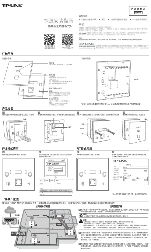
物品清单:一台无线面板式AP 螺钉一张AP安装记录标贴一本快速安装指南关注微信服务号在线客服在身边扫码下载TP-LINK商云APP背面示意图:*说明:应购买配套使用的获得CCC 认证并满足要求的标准PoE供电设备。
根据图示方向固定壳盖,完成安装4取下墙上的86型网络接线面板(若无盒盖,可忽略)1将墙壁中的网线接上水晶头,并将其插入背面板相应接口2对准AP与暗盒上的螺丝孔,装入螺钉以固定,请勿将螺钉拧得过紧3FAT模式应用把AP模式开关拨到FAT模式,如下图。
1登录AP管理界面(首次登录需自定义用户名和密码),2*以上所有软件界面图片仅为示意,请以实际界面为准。
FIT模式应用把AP模式开关拨到FIT模式,如下图。
1登录AC管理界面,如需了解AC设备的登录和使用方法,2“易展”配置TP-LINK“易展”AP可作为易展接入节点,供其他TP-LINK易展设备配对接入,构建分布式Wi-Fi网络,其组网拓扑和组网配置步骤如下:选择邻近插座,将其他“易展”子设备接通电源,待其系统启动完成后按下其“易展”按键触发设备配对状态;当易展子设备的指示灯变为红色闪烁,表明易展子设备进入待配对状态,此时再按下AP“易展”按键,AP系统指示灯闪烁,表明正在配对;当AP指示灯常亮且易展子设备系统指示灯变为绿色常亮,表明配对完成,实现“一键互联”。
TalkSwitch 48-CVA 安装指南说明书

START GUIDEINTRODUCTIONAbout this guideThis guide is designed to take you through the TalkSwitch installation andconfiguration in an easy-to-follow 8 step process. Once set up, your system can easilybe configured to add or change extensions, or to increase system capacity.Who should use this guideThis guide is intended for use with a TalkSwitch 24-CA, TalkSwitch 48-CA, or 48-CVAsystem (of single or multiple units).Where to go for further informationThe guides listed below, and other guides, can be found on the TalkSwitch software CD,in the TalkSwitch folder in the Windows Start menu once the software has beeninstalled, and in the support section of our website at /support.•For advanced configuration instructions, refer to the TalkSwitch User Guide after completing the steps in this guide.•For information on setting up a TalkSwitch 48-CVA system to use VoIP, refer to the TalkSwitch VoIP Configuration Guide for Multi-location Networks.•For information on configuring your system remotely, refer to the RemoteConfiguration Quick Guide.TroubleshootingThe TalkSwitch system and the configuration software are designed for ease of use.However, if you encounter difficulties with the installation or configuration of yourTalkSwitch:•Consult the documents on the TalkSwitch software CD or in the TalkSwitch folder on your PC.•Access additional TalkSwitch information online, including FAQs and Quick Guides, at /support.Contacting TalkSwitch Technical Support•Contact your reseller.•Email **********************, providing your company name and TalkSwitch product information.•Call our support line at 1-866-393-9960 (toll free in continental North America) or at (613) 725-2466, Monday to Friday from 9:00 am to 5:00 pm EST.W W W.T A L K S W I T C H.C O M12T A L K S W I T C H S T A R T G U I D EBEFORE YOU BEGINCheck package contents:Whether you have purchased a system with one or multiple TalkSwitch units, each package you receive should include the following:•TalkSwitch unit•TalkSwitch Configuration Software CD •AC Adapter•RJ-11 telephone cables (4 for 48-CA and 48-CVA; 2 for 24-CA)•RJ-45 Ethernet cable (for 48-CA and 48-CVA) or USB cable (for 24-CA)•Quick Reference Cards (8 for 48-CA and 48-CVA; 4 for 24-CA)•Wall mounting template, screws and anchors for optional wall-mounting your TalkSwitch unit.Ensure that you have the minimum system requirementsYou will need a PC to configure your TalkSwitch. Ensure that your PC meets the following minimum system requirements:•Windows 2000/ XP operating system •120 MB free hard disk space •128 MB RAM•800x600 video resolutionNetwork equipment: If your system includes multiple TalkSwitch 48 units, you will need an Ethernet switch. If you plan on using VoIP or configuring your systemremotely, you will need an Ethernet switch (or router with an integrated switch) and a broadband Internet connection.Check your premises telephone wiringTalkSwitch usually doesn’t require any extra telephone wiring beyond the standard infrastructure in most commercial and residential buildings. If your premises requires additional wiring, refer to the Home/Office Wiring Quick Guide or consult an Authorized TalkSwitch Reseller in your area.Important! Lightning and electrical surges can cause damage to theTalkSwitch unit. We recommend using surge protection equipment on allexternal telephone and power lines connected to this device.STEP 1 – INSTALL THE TALKSWITCH SOFTWARE 1.Turn your computer on, and insert the CD into theCD-ROM drive.2.The Install main window will appear within 20seconds. Click INSTALL and follow the instructions.Note: If you are using Windows XP or 2000, ensure that you have Administrator privileges.If the installation program does not automaticallystart (for example, if Autorun is disabled on your PC):1.From the desktop, double-click the My Computer icon.2.Double-click on the CD drive labeled TalkSwitch.3.Double-click on setup.exe located in the start folder.4.Click Installand follow the instructions.W W W.T A L K S W I T C H.C O M3STEP 2 –CONNECT TALKSWITCH TO YOUR PC OR NETWORK TalkSwitch can be set up anywhere in the vicinity of your incoming phone lines and computing equipment.•TalkSwitch 48-CA and 48-CVA can be connected using a Local Area Network (LAN), USB, or serial* (RS-232) connection.•The TalkSwitch 24-CA can be connected using a USB or serial* connection.If you’re installing a TalkSwitch system with multiple TalkSwitch 48-CA and/or 48-CVA units or you’re adding a TalkSwitch unit to an existing system, refer to the Networking TalkSwitch on a LAN section on page 14.Connect TalkSwitch to your PC or networkLAN (Ethernet) option: Connect one end of the providedRJ-45 Ethernet cable to the LAN port at the back of the TalkSwitch 48-CA or 48-CVA unit and the other end directly to your Ethernet switch. Ensure your computer is connected to the same switch.USB option: Connect one end of a USB cable to the USB port at the back of the TalkSwitch unit and the other end to the USB port of your PC.Power up TalkSwitch1.Connect the provided AC Adapter to the Power port atthe back of the TalkSwitch unit and plug the adapter into an available power outlet.Warning! Never use a power adapter other thanthe one provided with TalkSwitch.2.Turn TalkSwitch on by pressing the Power button onthe front of the unit. The lights on the front panel will flash for a few moments during boot-up, then stop.The center light marked Data will remain lit,indicating that the TalkSwitch unit is on.*Serial cables are not provided with TalkSwitch NUSBPowerDataPower4T A L K S W I T C H S T A R T G U I D ESTEP 3 – OPEN THE TALKSWITCH CONFIGURATION SOFTWARE Double-click the TalkSwitch icon on your Desktop (thisicon was created during the software installation), or fromthe Start menu, select Programs, select the TalkSwitch3.21 folder, and click TalkSwitch Configuration 3.21.LAN connectionA progress bar appears on the screen showing theconnection to TalkSwitch in progress. When the bardisappears, the TalkSwitch System Configuration windowwill appear.USB connectionA dialog box opens requesting you to select theconnection type. Select USB connection from thedrop-down list and click Connect... A progress bar appearson the screen showing the connection in progress. Whenthe bar disappears, the TalkSwitch System Configurationwindow will appear.Note: If you encounter difficulties opening the TalkSwitch configuration software, check that all your wires andplugs are securely connected.W W W.T A L K S W I T C H.C O M5STEP 4 – CONFIGURE AN AUTOMATED ATTENDANTAn Auto Attendants can be set up to answer incoming calls and play a recorded greeting. For example, an Auto Attendant greeting can instruct callers to dial their party’s extension or dial ‘0’ for assistance.If you do not wish to set up an Auto Attendant at this time, you can proceed to the Step 5 — Configure Incoming Telephone Lines.Set up an Auto Attendant1.In the TalkSwitch System Configuration window,select Call Handling and then Auto Attendant fromthe menu at the left of the window.2.In the main panel of the window, click 1 to configureAuto Attendant number 1 (default selection).Additional Auto Attendants (up to 9) can be set uplater using the same procedure.3.From the drop-down lists next to If the caller selects“0” then:, select go to local ext., and then 114.We recommend assigning extension 114 to your office receptionist (or person assigned to answer generalcalls); extension 114 is designed to continue operating in the event of a power failure.If your office has other directory options (for example, dial 1 for sales), you can set these now.4.For callers that do not have a touchtone phone, go tothe section: After the Auto Attendant has finishedplaying and no selection has been made. From thedrop-down lists select the number of seconds to wait (for example, 5), select go to local ext., and select the receptionist's extension (for example, 114).123 46T A L K S W I T C H S T A R T G U I D EW W W.T A L K S W I T C H.C O M711Set up an Auto Attendant greetingYou can load a professionally pre-recorded greeting to TalkSwitch now or you can record your own Auto Attendant greeting after connecting your telephones to TalkSwitch. Recording an Auto Attendant greeting is described in Step 8 of this guide — Record Auto Attendant and Voicemail Greetings .To load a pre-recorded Auto Attendant greeting:1.Click on Load Auto Attendant..2.An information box opens asking whether or not tocontinue. Click Yes and follow the instructions.The file must be an 8khz, 8-bit, mono, µ-law .wav file. A sample greeting (Auto Attendant Sample.wav) is provided in your TalkSwitch folder.For more information: For complete details and options, such as Automatic Fax Detection, refer to the Creating an Auto Attendant and Detecting and Routing Faxes Quick Guides.STEP 5 – CONFIGURE INCOMING TELEPHONE LINESSetting up your incoming lines will customize TalkSwitch to fit the unique needs of your business. For example, you can set all incoming calls to be answered by an Auto Attendant, set certain extensions to ring before an Auto Attendant answers, or have calls go directly to voicemail.If you have not set up an Auto Attendant, proceed to the Set certain extensions to ring or direct calls to voicemail section on the next page.Set Auto Attendant to answer all incoming calls1.Select Call Handling and then Telephone Lines fromthe menu on the left of the TalkSwitch SystemConfiguration window.2.From the list of telephone lines, click Line 1 toconfigure incoming line number 1.3.From the drop-down list next to On an incoming callduring mode:, select Mode 1.Modes represent different operating schedules, such asstandard business operating hours or non-standard(weekends and evenings). Additional modes can beconfigured later.4.From the drop-down lists, select Play auto attendant,select 1, and select immediately.Auto Attendant 1 will immediately answer allincoming calls and play a greeting.5.For TalkSwitch 24-CA, repeat this process for Line 2.For TalkSwitch 48-CA and 48-CVA, repeat this process for Lines 2, 3, and 4.6.If you have a system with multiple TalkSwitch units,you will notice up to four tabs (TalkSwitch 1,TalkSwitch 2, etc.) across the top of the window. Click on each tab to configure each TalkSwitch unit in your network. 234 18T A L K S W I T C H S T A R T G U I D ESet certain extensions to ring or direct calls to voicemail Option 1To have certain extensions ring without playing an Auto Attendant, select R ing extensions only. S elect the extensions to ring from the list of extensions.Note: you can adjust the ring sequence by clicking Adjust Sequence...Option 2To have certain extensions ring before the Auto Attendant is played, select Play auto attendant. S elect the Auto Attendant to play (for example, 1), select the number of rings (for example, after 3 rings), and select the extensions to ring from the list (by default they are all selected).Note: you can adjust the ring sequence by clickingAdjust Sequence...Option 3To have all incoming calls directed to voicemail, select Go to voice mailbox, select the mailbox number (for example, 111), and the number of rings (for example, after 3 rings).For TalkSwitch 24-CA, repeat the process described in the options above for Line 2. For TalkSwitch 48-CA and 48-CVA, repeat the process for Lines 2, 3, and 4.If you have a system with multiple TalkSwitch 48 units, click on each tab (TalkSwitch 1, TalkSwitch 2, etc.) to configure all TalkSwitch units in a network. Option 1 Option 2 Option 3W W W.T A L K S W I T C H.C O M910T A L K S W I T C H S T A R T G U I D ESTEP 6 – SAVE SETTINGS TO TALKSWITCHThis step will transfer the settings you have configured from your computer to the TalkSwitch system.From the File menu in the TalkSwitch System Configuration window, select Save to TalkSwitch... A progress bar appears indicating that the configuration information is being sent to the TalkSwitch system.STEP 7 – CONNECT TELEPHONES AND PERIPHERALSConnect incoming (external) telephone linesImportant! Lightning and electrical surges can cause damage to TalkSwitch. We recommend using surge protection equipment on all external telephone and power lines connected to a TalkSwitch system.Single line connection (1 incoming phone line per wall phone jack)Use the RJ-11 telephone cables provided to connect external phone lines to TalkSwitch. These cables have a two-wire connector for connection to a single line wall jack.1.Connect one end of the provided RJ-11 telephone cableto the wall phone jack of an incoming phone line and the other end to the L1/L2 jack at the back of the TalkSwitch unit. 2.If necessary, connect a second external phone line tothe L2 jack of the TalkSwitch unit using the same method.3.If you have a TalkSwitch 48-CA or 48-CVA, connect theremaining external phone lines to the L3/L4 and L4jacks at the back of the TalkSwitch unit, respectively.Two-wire connectorL3/L4L1/L2L2L448-CA/48-CVAL1/L2L224-CAW W W.T A L K S W I T C H.C O M11Dual line connection (2 incoming phone lines per wall phone jack)Use four-wire RJ-11 telephone cables to connect external phone lines to TalkSwitch. These cables are not provided with the TalkSwitch unit.1.Connect one end of a four-wire RJ-11 telephone cableto the wall phone jack of the incoming phone lines and the other end to the L1/L2 jack of the TalkSwitch unit.2.For TalkSwitch 48-CA and 48-CVA, connect anotherdual external phone line to the L3/L4 jack of the TalkSwitch unit using the same method.Note: It is important that dual phone lines are connected to the L1/L2 and L3/L4 jacks, otherwise TalkSwitch will not recognize these lines as two separate lines.Connect telephones and fax machines to TalkSwitchFor TalkSwitch 24-CA , connect the telephone cables from your phones to the E1 through E4 jacks of the TalkSwitch unit, consecutively. If you have a fax, connect the phone cable from your fax to the E3 jack.For TalkSwitch 48-CA and 48-CVA , connect thetelephone cables from your phones to the E1 through E8 jacks of the TalkSwitch unit(s). If you have a fax, connect the phone cable from your fax to the E8 jack.Four-wire connectorL1/L224-CAL3/L4L1/L248-CA/48-CVAE1E2E3E4E1E2E3E4E5E6E7E848-CA/48-CVA24-CA12T A L K S W I T C H S T A R T G U I D ETake note of which telephone is connected to which jack and refer to the table below for corresponding extension numbers. For systems with multiple TalkSwitch 48 units, refer to the Networking TalkSwitch on a LAN section on page 14 for further details.Connect an audio source (optional)To play music while on hold, connect a 1/8" (3.5mm) mono phono connector cable from an audio source such as a CD player, tape player, or sound card to the MUSIC jack of the TalkSwitch unit.If you have a system with multiple TalkSwitch units, you will need to provide audio to the MUSIC jacks of each unit.TalkSwitch 48-CA and 48-CVATalkSwitch 24-CATalkSwitch Phone Jack E1E2E3E4E5E6E7E8Extension number (single unit systems; unit ID = 1)111112113114115116117118MUSICSTEP 8 – RECORD AUTO ATTENDANT AND VOICEMAIL GREETINGSIf you have not loaded a pre-recorded Auto Attendant greeting, as described inStep 4 of this guide — Configure an Automated Attendant, then you should recorda greeting now.What should an Auto Attendant say?The following is an example of a typical Auto Attendant greeting:"Welcome to the ABC company. If you know your party's three-digit extension you maydial it now. To reach reception, press '0' or stay on the line."Record an Auto Attendant greetingTo record an Auto Attendant greeting for Auto Attendant 1:1.Pick up any telephone connected to the TalkSwitch. You should hear a dial tone.2.Press then413.Follow the prompts to record your message.Set up and record voicemailTo set a password, record a personal greeting, and record your name for the companydirectory:1.Pick up any telephone connected to TalkSwitch. You should hear a dial tone.2.Dial and your mailbox number. Your mailbox number is equivalent to yourextension number.3.Follow the prompts to set a password, record a personal greeting, and record yourname for the company directory.W W W.T A L K S W I T C H.C O M1314T A L K S W I T C H S T A R T G U I D ENETWORKING TALKSWITCH ON A LANUp to four TalkSwitch 48-CA and/or 48-CVA units can be networked together over a LAN to increase the number of lines and extensions in your system. For further details on networking multiple TalkSwitch units, refer to the Networking TalkSwitch Quick Guide.Connect TalkSwitch unitsUse LAN cables to connect each TalkSwitch to your Ethernet switch.Note: TalkSwitch unit enclosures are not designed for stacking. We recommendwall-mounting units in a horizontal row to maximize airflow and keep the units from overheating.Power up all TalkSwitch units1.Connect the provided AC Adapters to the Power ports of each TalkSwitch unit andplug each adapter into an available power outlet.2.Turn the TalkSwitch units on by pressing the Powerbutton on the front of each unit.Change TalkSwitch unit ID numbersEach TalkSwitch unit is identified by a unique unit ID number. Unit ID numbers helpidentify the extensions and voice mailboxes associated with each unit. For example,the first extension on unit 1 is 111. On unit 2, it’s 121, on unit 3 it’s 131, and so on.Refer to the following table:Unit ID 1Unit ID 2Unit ID 3Unit ID 4Local Extensions111-118121-128131-138141-148Local Mailboxes111-118121-128131-138141-148Each TalkSwitch unit is pre-programmed at the factory with Unit ID number 1. Whenyou plug multiple units in for the first time or add a unit or units to an existingnetwork, the lights on the front of each TalkSwitch flash. This is an indication that allunits have the same ID number. Change the ID numbers so that they are all unique, asfollows:1.Connect a phone to any extension jack of the TalkSwitch unit for which you wantto change the unit ID number, and lift the phone handset.2.The TalkSwitch prompt will indicate that there is an ID conflict. Choose a number,for example "2", as the new unit ID number. Once the unit ID number has beenaccepted, the lights on the front panel will stop flashing (usually within10 seconds).3.Repeat the above steps for each additional TalkSwitch unit, assigning a unique IDnumber to each unit on the network.What next? Now that you have connected your TalkSwitch units and changed the unitID numbers, you can configure call handling options for TalkSwitch. Return toStep 3 — Open the TalkSwitch Configuration Software and follow the remainingsteps described in this guide.W W W.T A L K S W I T C H.C O M15SETUP COMPLETECongratulations!You have successfully set up your TalkSwitch system and are ready to accept incomingcalls. The Quick Reference Cards provided with TalkSwitch should be given to eachemployee in order that they know how to use the TalkSwitch features.Configuring TalkSwitch 48-CA and 48-CVA remotelyOnce installation is complete, you can configure your TalkSwitch 48-CA or 48-CVA via aTCP/IP connection between TalkSwitch and a remote PC running the TalkSwitchconfiguration software. For details, refer to the TalkSwitch Remote Configuration QuickGuide.Note: If TalkSwitch is installed behind a router/firewall, you will need to map port9393 to TalkSwitch to enable remote configuration (for details on port mapping, visit/routers.htm).What next•For advanced configuration and complete information on TalkSwitch features, refer to the TalkSwitch User Guide.•To add remote extensions to your TalkSwitch system, refer to the Adding Remote Extensions Quick Guide.•To configure your TalkSwitch 48-CVA (or upgraded 48-CA) system to use VoIP, refer to the TalkSwitch VoIP Configuration Guide for Multi-location Networks.16T A L K S W I T C H S T A R T G U I D ETalkSwitch. Copyright 2005.All Rights Reserved.Document number: CT.TS005.025.EN - 01 (May 2005) TalkSwitch is a division of Centrepoint Technologies Inc.。
NETGEAR 智能交换机安装指南说明书
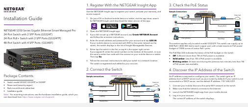
1. Register With the NETGEAR Insight AppUse the NETGEAR Insight app to register your switch, activate your warranty, and access support.1. On your iOS or Android mobile device or tablet, visit the app store, searchfor NETGEAR Insight, and download the latest version of the app.2. Open the NETGEAR Insight app.3. If you did not set up a NETGEAR account, tap Create NETGEAR Accountand follow the onscreen instructions.4. Enter the email address and password for your account and tap LOG IN .24-Port Switch with 2 SFP Ports (GS324T)24-Port PoE+ Switch with 2 SFP Ports (GS324TP) 3. Check the PoE StatusNETGEAR, Inc.350 East Plumeria DriveSan Jose, CA 95134, USA NETGEAR INTL LTDBuilding 3, University Technology Centre Curraheen Road, Cork, Ireland© NETGEAR, Inc., NETGEAR and the NETGEAR Logo are trademarks of NETGEAR, Inc. Any non‑NETGEAR trademarks are used for reference purposes only.SupportThank you for purchasing this NETGEAR product. You can visithttps:///support/ to register your product, get help, access the latest downloads and user manuals, and join our community. We recommend that you use only official NETGEAR support resources.Si ce produit est vendu au Canada, vous pouvez accéder à ce document en français canadien à https:///support/download/.(If this product is sold in Canada, you can access this document in Canadian French at https:///support/download/.)For regulatory compliance information including the EU Declaration of Conformity, visit https:///about/regulatory/.See the regulatory compliance document before connecting the power supply.Do not use this device outdoors. If you connect cables or devices that are outdoors to this device, see https:///000057103 for safety and warranty information.November 20185. Configure the SwitchWe recommend that you use a web browser on a computer or tablet to configure the switch.Note: If your computer is a Mac, use the NETGEAR Switch Discovery Tool, as described in the following section.1. Open a web browser from a computer or tablet connected to the samenetwork as your switch.You can use a WiFi or wired connection. 2. Enter the IP address of the switch.3. Enter the password.The default password is password . We recommend that you change the password to a more secure password.4. Click the Login button.Other Discovery and Configuration MethodsThe NETGEAR Switch Discovery Tool and the Smart Control Center Utility let you discover the IP address and configure the switch. •NETGEAR Switch Discovery Tool . You can use a Mac or a 64-bit Windows-based computer that is on the same network as the switch. You can use a WiFi or wired connection. When you discover the switch, this tool provides access to the local browser interface to c onfigure the switch. To download the NETGEAR Switch Discovery Tool, visit/support/product/netgear-switch-discovery-tool.aspx .•Smart Control Center Utility . You can use a Windows-based computer that is on the same network as the switch. This utility requires Adobe Air. If Adobe Air is not detected during Smart Control Center Utility installation, you are prompted to allow Adobe Air to be installed. To download this utility, visit /support/product/SCC .Note: If you cannot discover or configure the switch, you might need totemporarily disable the firewall, Internet security, or antivirus programs. Make sure to reenable these security services after you discover and configure the switch.PoE ConsiderationsThe PoE and PoE+ power supplied by the GS324TP switch is prioritized inascending port order (from port 1 to port 24), with a total power budget of 190 watts. If the power requirements for the attached powered devices (PDs) exceed the total power budget of the switch, the PD on the highest-numbered port is disabled to make sure that the PDs that are connected to the higher-priority, lower-numbered ports are supported first.The following table describes the PoE classes and switch allocations.Device ClassStandard ClassDescriptionPowerReserved by the DevicePower Delivered to the Device*0PoE and PoE+Default power (full)15.4W 0.44W–12.95W 1PoE and PoE+Very low power 4.0W 0.44W–3.84W 2PoE and PoE+Low power 7.0W 3.84W–6.49W 3PoE and PoE+Mid power 15.4W 6.49W–12.95W 4PoE+ onlyHigh power30.0W12.95W–25.5W* Calculated with the maximum cable length of 328 feet (100 meters). Shorter cable lengths will provide power closer to the power reserved by the switch.。
NETGEAR 适配器快速安装指南说明书
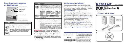
Guide d'installationNETGEAR, le logo NETGEAR et Connect with Innovation sont des marques commerciales et/ou des marques déposées de NETGEAR, Inc. et/ou des iliales de NETGEAR aux Etats-Unis et/ou dans d'autres pays. Ces informations sont susceptibles d'être modifiées sans préavis. © NETGEAR, Inc. Tous droits réservés.Pour une utilisation en intérieur seulement. Destiné à être vendu dans tous les États membres de l'UE, les états de l'AELE et la Suisse.Mars 2013NETGEAR, Inc.350 East Plumeria DriveSan Jose, CA 95134 USADescription des voyants et des boutonsElémentDescriptionVoyant d'ali-mentation •Vert continu . L'adaptateur est sous tension.•Orange continu . L'adaptateur est en mode veille.•Vert clignotant . Le processus d'appairage/de sécurisation de l'adaptateur est en cours.•Eteint . L'adaptateur est hors tension.Voyant Ethernet•Continu . L'adaptateur est connecté par l'intermédiaire du port Ethernet à un dispositif Ethernet alimenté. •Eteint . Aucune connexion Ethernet disponible.Bouton de réinitialisationBouton de sécuritéVoyant CPLVoyant Ethernet Voyant d'alimentation CPL 200 Mini (pack de 2) XAVB1301Assistance techniqueNous vous remercions d'avoir choisi les produits NETGEAR. Après l'installation de votre périphérique, notez le numéro de série inscrit sur l'étiquette située sous votre produit. Il vous sera nécessaire pour enregistrer votre produit à l'adresse https:// .Vous devez être enregistré pour utiliser notre serviced'assistance téléphonique. Nous vous recommandons vivement de procéder à l'enregistrement sur notre site Web.Pour obtenir des mises à jour de produits et consulter le support Web, rendez-vous à l'adresse gear.fr/support. NETGEAR vous recommande d'utiliser uniquement les ressources d'assistance officielles NETGEAR.Vous pouvez obtenir le manuel de l'utilisateur en ligne àl'adresse ou via un lien dans l'interface utilisateur du produit.Pour consulter la déclaration de conformité complète pour l'UE rendez-vous sur le site/app/answers/detail/a_id/11621/.Avertissement : avant d'appuyer sur le bouton de sécurité, attendez que l'installation de l'adaptateur CPL soit terminée et que les adaptateurs communiquent entre eux (voyant CPL clignotant). En appuyant trop tôt sur ce bouton, vous risquez de désactiver temporairement lacommunication CPL. Le cas échéant, appuyez sur le bouton de réinitialisation pour rétablir les paramètres par défaut de l'adaptateur CPL.Voyant CPL•Continu . L'adaptateur est connecté à un réseau CPL.•Eteint . L'adaptateur n'a pas trouvé d'autres périphériques CPL compatibles utilisant la même clé de fonctionnalité Pick A Plug vous permet de choisir la prise électrique comportant le plus fort débit de connexion, indiqué par la couleur du voyant :Vert : débit de connexion > à 80 Mbit/s (Rapide)Orange : débit de connexion > à 50 et < à 80 Mbit/s (Moyen)Rouge : débit de connexion < à 50 Mbit/s(Lent)Bouton de réinitialisa-tion Appuyez sur le bouton de réinitialisation pendant 1 seconde pour rétablir les paramètres par défaut de l'adaptateur CPL.Bouton de sécuritéAprès avoir branché votre nouvel adaptateur, appuyez sur le bouton de sécurité pendant 2 secondes, puis appuyez sur le bouton de sécurité de l'un des autres adaptateurs du réseau existant pendant 2 secondes. Vous devez appuyer sur les deux boutons dans un délai de 2 minutes.Pour activer le mode d'économie d'énergie, appuyez et maintenez le bouton sécurité pendant au moins 10 secondes, puis relâchez-le. Le fait d’appuyer à nouveau sur le bouton sécurité remet l'adaptateur sous tension.Elément DescriptionCâbles EthernetXAV2101, XAV2602, XAV1401, XAV1601, et XAVN2001 NETGEAR. Pour consulter la liste complète des périphériques certifiés HomePlug AV, rendez-vous à l'adresse /certified_rmations de sécurité•Prise secteur CA : 100-240 V~, 60 mA (max.).•Température de fonctionnement : 0 °C~35 °C.•La prise de courant doit être facilement accessible et se trouver à proximité de l'équipement.DépannageLe voyantd'alimentation estéteintAssurez-vous que la prise électrique est bien sous tensionet que les périphériques CPL ne sont pas branchés à unerallonge électrique, un bloc multiprise ou un dispositif deprotection contre les surtensions.Le voyantd'alimentation estorangeL'adaptateur CPL est en mode d'économie d'énergie. Pourrétablir l'adaptateur en mode normal, appuyez sur lebouton sécurité.Le voyant CPL estéteint•Si vous avez configuré la sécurité du réseau, assurezvous que tous les périphériques CPL utilisent la même cléde chiffrement. Pour plus d’informations, reportez-vous auManuel de l’utilisateur.•Appuyez sur le bouton de réinitialisation pendant1 seconde pour rétablir les paramètres par défaut del'adaptateur CPL.Le voyant CPL estorange ou rougeRapprochez le périphérique CPL.Le voyantEthernet est éteint•Assurez-vous que les câbles Ethernet sont branchés auxpériphériques et fonctionnent correctement.•Appuyez sur le bouton de réinitialisation pendant1 seconde pour rétablir les paramètres par défaut del'adaptateur CPL.。
網路型主控制器 主機快速安裝指南说明书
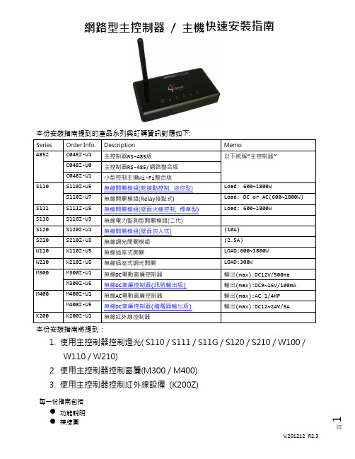
本份安裝指南提到的產品系列與訂購資訊對應如下:本份安裝指南將提到:1.使用主控制器控制燈光( S110 / S111 / S11G / S120 / S210 / W100 /W110 / W210)2.使用主控制器控制窗簾(M300 / M400)3.使用主控制器控制紅外線設備(K200Z)每一份指南包括●功能說明● 步驟說明每一份文件必需包括所有的資訊,目的是讓使用者只要簡單的文件就可以完成特定的工作。
下面 將針對每一份文件把所有需要的資訊說明。
主控制器規格:主控制器說明:LED 燈號電源接頭設定鍵網路接頭● 主控制器連接電源後, LED 電源 (Power) 燈亮起, 一般情況下,及 1、2、3 號, 共 3顆燈恆亮, 4 號燈熄滅 , Link 燈為網路狀態燈。
● 在安裝任何無線設備前, 必須將主控制器進入“學習(Learning)”模式。
請按住主控制器後面的設定按鍵持續3秒鐘然後放開, 主控制器面板前面上的LED 1 號燈會亮起, 2、3、4號燈熄滅, 這個時候主控制器已經進入“學習(Learning)”模式。
※ 重置主控制器如需將主控制器”重置”(Reset )為出廠預設。
請斷開電源,按住後面的設定鍵不放再上電,持續至面板前面上的LED 燈1、2、3、4號數次閃爍後亮起, 這個時候主控制器已經完成重置。
※ 開啟或關閉主控制器 Auto Route(自動路徑)功能主控制器出廠預設”Auto Route ”功能是"關閉"。
如需開啟或關閉主控制器”Auto Route ”功能。
請斷開電源,按住主控制器後面的設定鍵不放再上電,上電後隨即放開設定鍵,此時面板前面上的1、2、3號LED 燈持續閃爍,這個時候連續按三下設定鍵:如果1號LED 燈 亮起,即表示已 開啟 ”Auto Route ”功能。
如果1號LED 燈 未亮起,即表示已 關閉 ”Auto Route ”功能。
1. 使用主控制器控制燈光主控制器搭配燈光及開關控制器可以控制多個燈光及情境群組。
快速安装指南
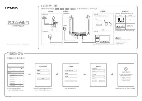
快速安装指南
双频无线路由器
双频无线路由器
电源适配器快速安装指南保修卡
物品清单:
(
未经普联技术有限公司明确书面许可,任何单位或个人不得擅自仿制、复制、誊抄或转译本手册部分或全部内容,且不得以营利为目的进行任何方式(电子、影印、录制等)的传播。
为普联技术有限公司注册商标。
本手册提及的所有商标,由各自所有人拥有。
本手册所提到的产品规格和资讯仅供参考,如有内容更新,恕不另行通知。
除非有特殊约定,本手册仅作为使用指导,所作陈述均不构成任何形式的担保。
Copyright © 2015 普联技术有限公司版权所有,保留所有权利
400-8863-400技术支持热线声明
公司网址
地址:深圳市南山区深南路科技园工业厂房24栋南段1层、
3-5层、28栋北段1-4层。
- 1、下载文档前请自行甄别文档内容的完整性,平台不提供额外的编辑、内容补充、找答案等附加服务。
- 2、"仅部分预览"的文档,不可在线预览部分如存在完整性等问题,可反馈申请退款(可完整预览的文档不适用该条件!)。
- 3、如文档侵犯您的权益,请联系客服反馈,我们会尽快为您处理(人工客服工作时间:9:00-18:30)。
压线钳
液压钳
热风枪
冷压端子 热缩套管
OT端子
12. 安装系统电源接地线(g1 )
将所有空开都置于OFF,检查手动电池上电开关至于Normal。
BAT ON
Normal
OFF OFF
OFF
将地线接到接地排上,并绑扎固定。
地线、交流线、直流线、信号线、通信线 均需分开绑扎,不能互相绑扎在一起!
站点接地排
如果蓄电池空开合上后,PMU没有任何显示,请将手动电池上电开关置于BAT ON。持续等待2分钟后 将其置于Normal,避免蓄电池长期保持强制吸合。如果当前蓄电池电压非常低,保持2分钟BAT ON后, 调回Normal会导致PMU下电,则继续保持BAT ON,直至市电导通2分钟后再调回Normal。
■ 人身安全
系统电源接线时,需按照本指南指导的接线顺序,首先安装地线以确保人身安全。 系统接线的操作人员必须具备基本的安全操作知识,需经过培训,掌握正确的操作方法,并具有相应作业资格。 进行接线操作时,工具要绝缘处理,要戴绝缘手套,避免触电。
安装工具
一字螺丝刀 M3/M4
十字螺丝刀 M3/M4
活动扳手
N L
RTN+ -48V
-48V测 量点1
-48V测 量点2
-48V测 量点3
5
检查机柜是否有掉漆,并对掉漆处及时补漆。
上电调试
1.接通蓄电池支路
如果蓄电池架或蓄电池柜有输出空开,则将空开置于ON;
如果没有输出空开,则将电池组拆除的串联铜排接回。
ON
10
系统电源配电单元的电池支路空开打到ON。
ON
蓄电池
满配
次要负载 主要负载
接线标号
线径
g1 系统电源接地线
25 mm2-黄绿
a1 交流输入电源线
25mm2-棕、蓝
d1 主要负载(BLVD)电源线 d2 次要负载(LLVD)电源线 d3 蓄电池电源线 s1 干接点/开关量/传感器/防雷信号线 s2 RS485/RS232/FE信号线
随客户配置 随客户配置 25 mm2-蓝色电缆与黑色电缆 / /
TP48200A-V1H0
快速安装指南
文档版本:01 发布日期:2011-04-14
HUAWEI TECHNOLOGIES CO., LTD.
安全注意事项
■ 遵守所有安全注意事项
为保障人身和设备安全,在安装、操作、维护设备时,请遵循设备上标识及手册中说明的所有安全注意事项。手 册中的“安全警告”、“注意”、“说明”事项,并不代表所应遵守的所有安全事项,只作为所有安全注意事项 的补充。在进行本公司产品、设备的各项操作时,必须严格遵守由华为公司提供的相关设备注意事项和特殊安全 指示。手册中列出的“安全警告”仅代表了华为公司知道的部分,华为公司不承担任何因违反通用安全操作要求 或违反设计、生产和使用设备安全标准而造成损失的责任。
BLVD空开
8
LLVD空开
5. 安装蓄电池电源线 (d3)
如果蓄电池架或蓄电池柜有输出空开,则将空开置于OFF;
如果没有输出空开,则将每组电池组其中一个串联铜排拆除。
OFF 打开电池支路转接排上的保护罩,将蓄电池正极接在电池支路正极转接排上,再将蓄电池负极接在电池支路负极转接排上。
电池支路 正极转接排
2.电池组数可以设置为0,1,2.请根据实际配置电池情况设置组数与容量。如果实际情况只接1组蓄电池,则
电池容量需根据电池具体接的熔丝位置设置对应的电池容量,例如电池接在BF1-则设置“电池容量1”,BF2-
则设置“电池容量2”。本指南以2组蓄电池分别为300Ah为例进行操作。
1
2
3
4
5
English 中文
7
4. 直流负载电源线接线 (d1,d2)
安装主要负载(BLVD)直流输出线(d1),次要负载(LLVD)直流输出线(d2)。
1.安装后, -48V线应在信号线的前面。空开接线需要把螺钉拧紧。 2 .空开电流降额表。
环
修 境 (℃)
额正
温
定
电
度
30
35
40
45
50
55
60
65
70
电
流
(A) 流
(A)
电池支路 负极转接排
BAT1+ BAT2+ BAT1BAT2-
电池组1
电池组2
- + -+
6. 安装交流输入线(a1) Nhomakorabea1.接交流输入线前,请将ACDB中对应的空开置于OFF。 2. 确保L、N线接线正确,不能接反。
先将零线接入到N接线端。 再将L线接入到L接线端。
ACDB
9
N L
7. 安装完成后检查
序号 检查内容
1
确认机柜安装及接线牢固(紧固螺钉后线缆不会被轻易拔出)。
2
将电缆理顺就近绑扎在绑线桥上。
3
检测蓄电池正负极连接正确,注意正负极不能接反。
4
测量火线与地线(测量L与接地排之间)、火线与零线(测量L、N之间) 、RTN+与-48V铜排是否短路(测量-48V测量点1、
-48V测量点2、-48V测量点3分别与RTN+母排之间) 。如有短路,则检查是否接线错误,确保上电之前没有短路现象。
详细描述 环境温湿度检测 水浸检测 电池温度检测 门磁检测 烟感检测 0~5V备用模拟量 开关量输入1 开关量输入2 开关量输入7 油机状态检测1 开关量输入6 交流掉电告警 直流欠压告警 系统电源故障告警 防雷器失效告警 熔丝断告警 风扇告警 交流防雷器告警检测 直流防雷器告警检测 和后台通信
备注 根据用户需求选接 根据用户需求选接 根据用户需求选接 出厂时已经接好 出厂时已经接好 根据用户需求选接 温控单元告警检测,出厂时已经接好
63
63
60.11 58.19 56.21 54.16 52.03 49.81 47.50 43.05
125
145
135
125
115
105
95
85
75
65
环境温度是指断路器安装的配电箱中的温度,1~63A的断路器参考温度为30(℃),80~125A的断路 器参考温度为40(℃)。
1 RTN+
2 -48V
■ 遵守当地法规和规范
操作设备时,应遵守当地法规和规范。
■ 人员要求
负责安装维护华为设备的人员,必须先经严格培训,掌握正确的操作方法及安全注意事项后,方可安装、操作和 维护设备。
■ 符号说明
表示有潜在风险,如果忽视这些文本,可能导致设备损坏、数据丢失、设备性能降低或不可预知 的结果。
表示是正文的附加信息,是对正文的强调和补充。
根据实际需要,当确认需要使用串口时,则使用RJ45头的线缆连接监控用户接口模块面板COM_ 485/232与上位机。
COM_ 485/232
RJ45:上位机通信接口
根据实际需要,当确认需要使用带外监控时,且系统电源配置了SNMP时。则使用RJ45头的线缆连接SNMP的FE口与上位机。
RTN+ -48V
负载分流器:有 显示器对比度:3 系统类型:
TP48300/A
ENT
负载分流器:有 显示器对比度:3 系统类型:
TP48300/A
ENT
负载分流器:有 显示器对比度:3 系统类型:
备用,根据用户需求选接 DIN3丝印端口实际对应的是开关量输入7 油机启停检测,根据用户需求选接 备用 根据用户需求选接 根据用户需求选接 根据用户需求选接 根据用户需求选接 根据用户需求选接 根据用户需求选接 出厂时已经接好 出厂时已经接好 根据用户需求选接
6
a 干接点/传感器/防雷信号线接线方法(s1)(选接)
外观 OT(M8) 冷压 冷压或OT 冷压或OT OT 干接点信号线为冷压端子、传感器信号线为多pin插座 RJ45
4
接线顺序:g1->s1,s2->d1,d2->d3->a1 电缆从机柜底部引入孔位:g1,a1,d3从机柜左侧走线孔引入,s1,s2,d1,d2从机柜右侧走线孔引入。
连接电缆前需要根据实际情况制作端子。
BAT ON
Normal
2.设置监控模块参数
1、CPMU01监控模块位置、操作按键盘、状态指示灯如图所示。 2、TP48200A系统电源工作正常,与主设备有通信时,CPMU01面板上ALM红灯不亮RUN绿灯慢闪烁; TP48200A系统电源工作正常,与主设备无通信时,CPMU01面板上ALM红灯不亮RUN绿灯常亮; TP48200A系统电源有严重故障时,CPMU01面板上ALM红灯常亮且蜂鸣器鸣叫,请参照《TP48200A 系统电源维护指南》进行故障排除。 3、在待机界面时同时按 “↓”与“Enter”可以减小LCD的对比度;同时按 “↑” 与“Enter”可以增大 LCD的对比度。 4、进入CPMU01菜单设置时,按“↓”或“↑”可以翻阅菜单及设置菜单选项值。在待机界面按“Enter” 可进入主菜单,在主菜单中按“Enter”可进入下一级子菜单,在子菜单设置时按可以保存菜单选项值。 按“Cancel”可退回上一级菜单并不保存所设置菜单值。 5、无告警的情况下,如果当前画面不在主页,没有按键操作超过5分钟自动转回主页,超过8分钟则 LCD背光灯关闭。 6、“参数设置”菜单需用户密码进入。“工程师高级设置”菜单,需要工程师密码进入。用户密码为 0#,工程师密码为11#,工程师、用户密码在菜单中可重设。
English 中文
English 中文
English 中文
ENT
2008-08-06 53.6VDC 227VAC 负载:0.2A 电池:0.0A
ENT
主菜单 运行信息 系统控制 参数设置