NetStor_iSUM750_快速安装指南_V7.0
win7下UG7.0的详细安装步骤

NX7.0安装方法。
下面开始介绍:第一步:放入光盘,光盘会自动开启,如果光盘没有自动运行,直接进入光盘,执行光盘里的【Launch.exe】来载入UGS NX 7.0的安装界面,如下图一所示:第二步:点击界面上的【Install NX】按钮,UGS NX 7.0安装方法就开始了,默认安装语言为中文简体,直接点击确定按钮,稍后出来了:欢迎欢迎使用UGS NX7.0 InstallShield Wizard页面,点击下一步按钮之后;出来安装类型选择页面,就默认的典型就好了,点下一步按钮;来到了目的地文件夹,这里如果你不想安装在C盘,可以点更改按钮,选择其他的位置,但是,你一定要记住安装的位置,不然,会给后面带来很大的麻烦,切记!这里我就保持默认不改了,UGS NX7默认安装位置是: C:\Program Files\UGS\NX7.0,点击下一步按钮;出来的是许可页面,如下图二所示:在上图,我们看到了输入服务器或许可证文件后面是:28000@gao-pc,这里的gao-pc是我测试的这台电脑的计算机名,你在安装UGS NX7.0的时候,要注意,在@后面的一定要是你的计算机名,且计算机名中不可以有中文等复杂字符,最好是英文字母或者数字等,也就是说服务器名必须是:28000@你的计算机名。
例如,你的计算机名是:,那么这里输入的服务器名或许可证文件就是:28000@输入正确之后,点击下一步按钮;接下来是NX语言的选择,选择要在运行NX时所用的语言,这里根据自己的需要选择吧,我选择的是简体中文,点击下一步按钮,再点安装按钮,安装程序开始往计算机里拷贝文件了。
第三步:进入光盘里的RegIT文件夹,复制NX7.0里的所有文件,将其粘贴到C:\Program Files\UGS\NX7.0\里头,也就是NX7.0文件夹里头。
我这里是复制到了C:\Program Files\UGS\NX7.0里面,那如果你在第二步里修改了安装的位置,那么你需要粘贴到对应的位置里,并覆盖掉同名的文件,在Windows 7系统里,会出现下面的提示:图三图四这里一定要选择替换。
DL750高级网络和PC连接Web服务器功能说明书
Advanced Networking and PC ConnectivityWeb Server FunctionsConnect the DL750 to your PC through the Ethernet connection. This allows for easy remote operation using Internet Explorer.FTPY ou can easily copyand paste files to andfrom a PC and theThe Wirepuller softwareprogram displays a screenimage of the DLon your PC so that you canmonitor waveform signals.In addition, you can use thePC’s mouse and keyboardHigh-Speed 10 MS/s 12-Bit Isolation Module (701250)Input channels2Input couplings AC, DC, GNDMaximum sampling rate10 MS/sA/D conversion resolution12 bits (150 LSB/div)Input type Isolated unbalancedFrequency range(–3 dB)1DC, up to 3 MHzInput range(10:1)50 mV/div to 200 V/div (in steps of 1, 2, or 5),(1:1) 5 mV/div to 20 V/div (in steps of 1, 2, or 5) Effective measurement range20 div (display range: 10 div)DC offset±5 divMaximum input voltage (1 kHz or less)In combination with 700929 (10:1) 2600 V (DC + ACpeak)Direct input (1:1) 6, 10250 V (DC + ACpeak)Maximum allowable in-phase voltageIn combination with 700929 (10:1) 3400 Vrms (CA T I), 300 Vrms (CA T II) In combination with 7019in steps of 1, 2, or 5+701954 (1:1) 9400 Vrms (CA T I), 300 Vrms (CA T II) Main unit only (1:1) 1142 V (DC + ACpeak) (CA T I and CAT II, 30 Vrms) DC accuracy1±(0.5% of 10 div)Input impedance 1 MΩ± 1%, approx. 35 pFConnector type Isolation type BNC connectorInput filter OFF, 500 Hz, 5 kHz, 50 kHz, 500 kHz Temperature coefficientZero point±(0.05% of 10 div)/°C (typical value)Gain±(0.02% of 10 div)/°C (typical value)High-Speed 1 MS/s 16-Bit Isolation Module (701251)Input channels2Input couplings AC, DC, GNDMaximum sampling rate 1 MS/sA/D conversion resolution16 bits (2400 LSB/div)Input type Isolated unbalancedFrequency range (–3 dB)1DC, up to 300 kHz (20 V/div to 5 mV/div)Input range(10:1)10 mV/div to 200 V/div (in steps of 1, 2, or 5)(1:1) 1 mV/div to 20 V/div (in steps of 1, 2, or 5) Maximum input voltage (1 kHz or less)In combination with 700929 (10:1) 2600 V (DC + ACpeak)Direct input (1:1) 6, 10140 V (DC + ACpeak)Maximum allowable in-phase voltageIn combination with 700929 (10:1) 3400 Vrms (CA T I), 300 Vrms (CA T II) In combination with 701901+701954 (1:1) 9400 Vrms (CA T I), 300 Vrms (CA T II)Main unit only (1:1) 1142 V (DC + ACpeak) (CA T I and CAT II, 30 Vrms) DC accuracy15 mV/div to 20 V/div±(0.25% of 10 div)2 mV/div±(0.3% of 10 div)1 mV/div±(0.5% of 10 div)Input impedance 1 MΩ± 1%, approx. 35 pFConnector type Isolated type BNC connectorInput filter OFF, 400 Hz, 4 kHz, 40 kHzTemperature coefficientZero point 5 mV/div to 20 V/div: ±(0.02% of 10 div)/°C (typical value)2 mV/div: ±(0.05% of 10 div)/°C (typical value)1 mV/div: ±(0.10% of 10 div)/°C (typical value)Gain 1 mV/div to 20 V/div: ±(0.02% of 10 div)/°C (typical value) High-Speed 10 MS/s 12-Bit Non-Isolation Module (701255)Input channels2Input couplings AC, DC, GNDMaximum sampling rate10 MS/sA/D conversion resolution12 bits (150 LSB/div)Input type Non-isolated unbalancedFrequency range (–3 dB)1DC, up to 3 MHzInput range(10:1)50 mV/div to 200 V/div (in steps of 1, 2, or 5)(1:1) 5 mV/div to 20 V/div (in steps of 1, 2, or 5) Effective measurement range20 div (display range 10 div)DC offset±5 divMaximum input voltage (1 kHz or less)In combination with 701940 (10:1)600 V (DC + ACpeak)Direct input (1:1)250 V (DC + ACpeak)DC accuracy1±(0.5% of 10 div)Input impedance 1 MΩ± 1%, approx. 35 pFConnector type Metal type BNC connectorInput filter OFF, 500 Hz, 5 kHz, 50 kHz, 500 kHz Temperature coefficientZero point±(0.05% of 10 div)/°C (typical value)Gain±(0.02% of 10 div)/°C (typical value)Adaptive passive probe (10:1)701940High-Voltage 100 kS/s 16-Bit Isolation Module (with RMS) (701260)Input channels2Input couplings AC, DC, GND, AC-RMS, DC-RMSMaximum sampling rate100 kS/sA/D conversion resolution16 bits (2400 LSB/div)Input type Isolated unbalancedFrequency range (–3 dB)1Waveform measurement modeDC, up to 40 kHzRMS measurement mode DC, 40 Hz to 10 kHzInput range(10:1)200 mV/div to 2000 V/div (in steps of 1, 2, or 5)(1:1)20 mV/div to 200 V/div (in steps of 1, 2, or 5) Effective measurement range20 div (display range 10 div)DC offset±5 divMaximum input voltage (1 kHz or less)In combination with 700929 (10:1) 21000 V (DC + ACpeak)In combination with 701901+701954 (1:1) 6850 V (DC + ACpeak)Maximum allowable in-phase voltageIn combination with 700929 (10:1)H side: 1000 Vrms (CAT II) 4, L side: 400 Vrms (CAT II) 5In combination with 701901+701954 (1:1)H side: 700 Vrms (CA T II) 7, L side: 400 Vrms (CA T II) 8Direct input (when using a cable which doesn’t comply with the safety standard)H/L sides: 30 Vrms (42 V DC + ACpeak)11 DC accuracy (waveform measurement mode)1±(0.25% of 10 div)DC accuracy (RMS measurement mode)1±(1.0% of 10 div)AC accuracy (RMS measurement mode)1Sine wave input±(1.5% of 10 div)Crest factor of 2 or less±(2.0% of 10 div)Crest factor of 3 or less±(3.0% of 10 div)Input impedance 1 MΩ± 1%, approx. 35 pFConnector type Isolated type BNC connectorInput filter OFF, 100 Hz, 1 kHz, 10 kHzT emperature coefficient (waveform measurement mode)Zero point±(0.02% of 10 div)/°C (typical value)Gain±(0.02% of 10 div)/°C (typical value) Response time (RMS mode)Rise (0 to 90% of 10 div)100 ms (typical)Fall (100 to 10% of 10 div)250 ms (typical)Crest factor (only at RMS measurement)3 or less*Please use 701901 (1:1 safety adaptor lead) or 700929 (10:1 safety probe), which complies with the safety standard, for high-voltage input.*It is very dangerous to use cables that do not comply with the safety standard.Temperature/High-Precision Voltage Module (701265)Input channels2Input couplings TC (thermocouple), DC, GNDInput type Isolated unbalancedApplicable sensors (input coupling: TC)K, E, J, T, L, U, N, R, S, B, W, iron-doped gold/chromel Data updating rate500 HzFrequency range (-3 dB)1DC, up to 100 HzVoltage accuracy1 (at voltage mode)±(0.08% of 10 div + 2 µV)T emperature measurement accuracy 1, 12Type Measured range AccuracyK–200°C to 1300°C±(0.1% of reading + 1.5°C)E–200°C to 800°C except –200 to 0°C:J–200°C to 1100°C±(0.2% of reading + 1.5°C) T–200°C to 400°CL–200°C to 900°CU–200°C to 400°CN0°C to 1300°CR, S0°C to 1700°C±(0.1% of reading + 3°C)except0 to 200°C: ±8°C200 to 800°C: ±5°C B0°C to 1800°C±(0.1% of reading + 2°C),except 400 to 700°C: ±8°CEffective range: 400 to 1800°C W0°C to 2300°C±(0.1% of reading + 3°C)Iron-doped gold/chromel0 to 300 K0 to 50 K: ±4 K50 to 300 K: ±2.5 KMaximum input voltage (1 kHz or less)42 V (DC + ACpeak) (CAT I and CA T II, 30 Vrms)Input range (for 10 div display)100 µV/div to 10 V/div (in steps of 1, 2, or 5) Input connector Binding postInput impedance Approx. 1 MΩInput filter OFF, 2 Hz, 8 Hz, 30 HzT emperature coefficient (for voltage)Zero point±((0.01% of 10 div)/°C + 0.05 µV)/°C (typical value)Gain±(0.02% of 10 div)/°C (typical value) Strain Module (NDIS) (701270)Input channels2Input types DC bridge input (automatic balancing), balanceddifferential input, DC amplifier (floating) Automatic balancing method Electronic auto-balanceAutomatic balancing range±10,000 µSTR (1 gauge method)Bridge voltages Select from 2 V, 5 V, or 10 VGauge resistances120 to 1000 Ω (bridge voltage of 2 V)350 to 1000 Ω (bridge voltage of 2/5/10 V) Gauge rate 1.90 to 2.20 (variable in steps of 0.01)A/D resolution16 bits (4800 LSB/div: Upper=ϩFS, Lower=–FS) Maximum sampling rate100 kS/sFrequency range (–3 dB)1DC, up to 20 kHzDC accuracy1±(0.5% of FS + 5 µSTR)Measurement range/measurable rangeMeasurement range (FS)Measurable range (–FS to +FS)500 µSTR–500 µSTR to 500 µSTR1000 µSTR–1000 µSTR to 1000 µSTR2000 µSTR–2000 µSTR to 2000 µSTR5000 µSTR–5000 µSTR to 5000 µSTR10,000 µSTR–10,000 µSTR to 10,000 µSTR20,000 µSTR–20,000 µSTR to 20,000 µSTRmV/V range support mV/V range = 0.5 ϫ (µSTR range/1000)Maximum allowable input voltage (1 kHz or less)10 V (DC + ACpeak)Maximum allowable in-phase voltage42 V (DC + ACpeak) (CAT I and CA T II, 30 Vrms)T emperature coefficientZero point±5 µSTR/°C (typical value)Gain±(0.02% of FS)/°C (typical value)Internal filter OFF, 1 kHz, 100 Hz, 10 HzInput connector NDIS standardAccessory (a set of connector shell for solder connection)2 NDIS connectors (A1002JC)Recommended bridge head (NDIS type) (sold separately)701955 (bridge resistance of 120 Ω) (w/ 5 m cable)701956 (bridge resistance of 350 Ω) (w/ 5 m cable)10Alligator clip (701954)Isolated probe (700929)Safety adaptor lead (701901)Earphone Mic (w/ PUSH switch) (701951)701280 Frequency Module■ Frequency Measurement SectionInput channels2Data update rate25 kHz (40 µs)Measurement range(frequency)0.01 Hz–200 kHz0.1 Hz/div–50 kHz/divHighest measurement resolution50 ns (20 MHz)■ Input SectionCompatible input signals Encoder pulse input of up to ±42 V,Electromagnetic pickup input 6AC power input up to 300 Vrms (700929 Isolation Probe required) Input type Isolated, unbalancedInput coupling AC,DCInput voltage (1:1)±1 V–±50 V (6 ranges, 1-2-5 steps)(10:1)±10 V–±500 V (6 ranges, 1-2-5 steps)Max input voltage (1 kHz or less)When combined with 700929 (10:1) 2420 V (DC+ACpeak)Direct input (1:1) 1042 V (DC+ACpeak)Max allowable common mode voltageWhen combined with 700929 (10:1) 3300 Vrms (CAT II)Direct input (1:1) 1142 V (DC+ACpeak) 30 Vrms (CAT II)Input impedance: 1 MΩ±1%, approx. 35 pFConnector type Isolated BNC connectorInput filters OFF/100 Hz/1 KHz/10 KHz/100 KHzInput pullup function (ON/OFF)Supports open collector, mechanical contact output, 4.7 KΩ(+5 V) Input chatter suppression (ON/OFF)Setting range 1 ms–1000 msComparator section Presets Logic (5 V/3 V/12 V/24 V), electromagnetic pickup, zero-cross,pullup (5 V), AC100 V, AC200 V, user-definedThreshold range±FS range, resolution in units of 1%Hysteresis±1%, ±2.5%, or ±5% of FSLED display (each CH)ACT (green)Operational status (illuminates during pulse input)OVER (red)Overdrive status (illuminates during an input overrange) Compatible probes/cables(10:1 probe) 700929/701940 (1:1 cable) 366926■ Measurement Function DetailsMeasurable items Frequency (Hz), rpm, rps, Period (sec), Duty (%), Power supplyfreq. (Hz), Pulse width (sec), Pulse integration, Velocity Effective measurement range20 div (10 div display range)Resolution of measured data16 bit (2400 LSB/div)Measurement items and rangesMeasured Item Measurement Range RangeFrequency (Hz)0.01 Hz–200 kHz0.1 Hz/div–50 kHz/divrpm0.01 rpm–100,000 rpm0.1 rpm/div–10,000 rpm/divrps0.001 rps–2000 rps0.01 rps/div–200 rps/divPeriod (sec) 5 µs–50 s10 µs/div–5 s/divDuty (%)0%–100%1%/div–20%/divPower supply freq (Hz)(50 Hz, 60 Hz, 400 Hz)±20 Hz0.1 Hz/div–2 Hz/divPulse width (sec) 2 µs–50 s10 µs/div–5 s/divPulse integration up to 2ϫ109 count100ϫ10-21/div–500ϫ1018/divVelocity Same as freq. (can be converted to km/h and other units) Auxiliary M easurement Functions■ Smoothing Filter Apply moving average to smooth stair step shaped waveforms.(moving average)Moving average constant is specified from 0.2 ms to 1000 msec(moving average constant=specified time ÷40 µs) This reduces jitterand increases the resolution.■ Pulse Average Function Measure the specified number of pulses at once, and specify 1 to4096 pulses for the average value output mode. This has the exactsame effect as the smoothing filter, but averaging can be performedat the pulse interval. Even if encoder gaps are unequal, you canmeasure pulses together and average them.■ Deceleration Prediction A measuring function that automatically compensates for the lack of (Braking Applications)encoder pulse information during deceleration and hypothesizes adeceleration curve.■ Stop Prediction Predicts stop from a specified time after pulse stop(Braking Applications)(set up to 10 stages).■ Offset Observation Function Set an observational center, then zoom and display surroundingarea (for fluctuation observation)Offset setting range = (1 div ϫ 1000)■ M easurement Accuracy 1 5■ Frequency/Revolution/Velocity MeasurementsM easurement accuracy±( 0.05% of 10 div + accuracy depending on the input frequency) Accuracy depending on the input frequency 1 Hz–2 kHz:0.05% of input waveform freq +1 mHz2 kHz–10 kHz:0.1% of input waveform freq10 kHz–20 kHz0.3% of input waveform freq20 kHk–200 kHz0.5% of input waveform freq■ Period MeasurementM easurement accuracy±( 0.05% of 10 div + accuracy depending on the input period) Accuracy depending on the input period500 µs–50 s0.05% of input waveform interval100 µs–500 µs0.1% of input waveform interval50 µs–100 µs0.3% of input waveform interval5 µs–50 µs0.5% of input waveform interval + 0.1 µs■Duty MeasurementAccuracy depending on the input frequency0.1 Hz–1 kHz±0.1% of 100%1 kHz–10 kHz±0.2% of 100%10 kHz–50 kHz±1.0% of 100%50 kHz–100 kHz±2.0% of 100%100 kHz–200 kHz±4.0% of 100%■Pulse Width MeasurementM easurement accuracy±( 0.05 % of 10 div + accuracy depending on the input pulse width) Accuracy depending on the input pulse width500 µs–100 s0.05% of input waveform pulse width100 µs–500 µs0.1% of input waveform pulse width50 µs–100 µs0.3% of input waveform pulse width2 µs–50 µs0.5% of input waveform pulse width + 0.1 µs■Power Supply Frequency MeasurementM easurement accuracy Center freq. at 50, 60 Hz, accuracy of ±0.03 Hz, resolution of 0.01 HzCenter freq. at 400 Hz, accuracy of ±0.3 Hz, resolution of 0.01 Hz 1Under standard operating conditions: (temperature 23˚C±5˚C, humidity 55%±10% RH, warmup of at least 30 minutes, and after calibration.)5Given a minimum input of 0.2 Vpp. M easurement conditions:■During freq./Period measurement: 1 Vpp/1µs square wave input (range=±10 V, bandwidth=FULL,hysteresis=±1%)■During Duty/pulse width measurement: 1 Vpp/5 ns square wave input (range=±10 V, bandwidth=FULL, hysteresis=±1%)■During power supply frequency measurement: 90 Vrms sinewave input (range=AC100 V, BW=100 kHz)6Electromagnetic pickup: given output within 0.2 Vpp–42 Vpp. Minimum sensitivity=0.2 V (at 1:1), connected with 1:1 cable. For types that requires a power supply or terminal resistance, apply it to the sensor side 700929In combination with 700929HL3524HLBNC1110Direct input(With a cable which doesn’t comply with the safety standard)701275 Acceleration/Voltage Module (with AAF)Input channels2Input format Switchable between acceleration and voltage inputAAF (anti-aliasing filter) supports both acceleration and voltage Input coupling(AC coupling for acceleration) ACCL, (voltage) AC,DC,GND Max sampling rate100 kS/sA/D conversion resolution16-bit (2400 LSB/div)Input type Isolated, unbalancedFrequency band (-3 dB)1(acceleration) 0.4 Hz–40 kHz (voltage) DC–40 kHzAC coupling (-3 dB point)acceleration/voltage0.4 Hz or lessInput rangeFor acceleration (±5 V=X1 range)X0.1–X1–X100 (1-2-5 steps)For voltage (10:1)50 mV/div–100 V/div (1-2-5 steps) 12For voltage (1:1) 5 mV/div–10 V/div (1-2-5 steps) 12Effective measuring range20 div (10 div display range)DC offset±5 divMax input voltage (1 kHz or less) 1242 V (DC+ACpeak)Max allowable common mode voltage 1142 V (DC+ACpeak) 30 Vrms (CAT II)Accuracy 1For voltage (DC accuracy)±(0.25% of 10 div)For acceleration (AC accuracy)±(0.5% of 10 div) (at 1 kHz)Input impedance 1 MΩ±1%, approx. 35 pFConnector type Metal BNC connectorInput filters OFF/Auto (AAF)/4 kHz/400 Hz/40 HzAnti-aliasing filter (AAF)Cutoff frequency 13fc (cutoff frequency)=fs (sampling frequency) ϫ 40%fc automatically moves to the sampling frequency.Cutoff characteristics-65dB at 2Xfc (Typical)Temperature coefficient (for voltage) 14Zero point±( 0.02% of 10 div )/ ˚C (Typical)Gain±( 0.02% of 10 div )/ ˚C (Typical)Acceleration sensor bias constant current drive =4 mA±10%, voltage < 22 VExample of compatible acceleration sensor: 15Built-in amp type: Kistler Piezotron™, PCB ICP™, Endevco: Isotron2™Something that supports acceleration sensor and bias is 4 mA/22 V Sensor usage Notes:The sensor is highly sensitive to heat and shocks. If changes intemperature or shocks occur that are outside of the standardoperating conditions, measurement may not be possible for severalminutes.Compatible probes/cables for voltage(10:1 probe) 701940/700929 (1:1 cable) 3669261Under standard operating conditions: (temperature 23˚C±5˚C, humidity 55%±10%RH, warmup of at least 30 minutes, and after Calibration.)12The module’s insulation is functional insulation. Even when using a probe, input above 42 V is not considered safe.13when fs= 50 Hz–100 kHz , (when fs <=50 Hz , fc is fixed to 20 Hz)14 excludes AUTO Filter15Piezotron is a registered trademark of Kistler Instrument Corp.. ICP is a registered trademark of PCB Piezotronics Inc.. ISOTRON2 is a registered trademark of ENDEVCO Corp..For detailed specifications and updated information. /tm/DL750/2. Choose only one.3. Zip drive and DC12V power supply cannot be specified together with the DL750P .4. Cannot be specified together.6. The latest firmware for the DL750 series is available on our Web site./tm/DL750/7.Only supported by the initially-released DL750P (ver. 5.01 or later).DL750 support to be offered by 3rd quarter 2005 (ver. 6.01 or later)Universal (Voltage/Temperature) Modules (701261/701262)DL750/DL750P Accessories DL750/DL750P Model Numbers and Suffix CodesPlug-in Module Model Numbers 52. 42 V is safe when using the 701940 with a Non isolated type BNC input.3. The number of current probes that can be powered from the main unit probe power is limited. See the following for details. /tm/probe/4. There is no limit to the number of externally powered probes that can be used.5. One of each connection lead (B9879PX and B9879KX) is included.Input channels 2Input signals Voltage or temperature (thermocouple)AAF (anti-aliasing filter)701261: none, 701262: includedInput couplings TC (thermocouple), DC, AC, GNDInput typesI Isolated unbalancedMaximum sampling rate Voltage 100 kS/sData updating rate Temperature 500 HzA/D conversion resolution Voltage: 16 bits (2400 LSB/div); temperature: 0.1°CFrequency range (-3 dB)Voltage DC to 40 kHzTemperature DC to 100 HzInput range Voltage (1:1) 5 mV/div to 20 V/div (10 div display, in steps of 1-2-5)Temperature K, E, J, T , L, U, N, R, S, B, W, iron-doped gold/chromelEffective measurement range (voltage)20 div (display range 10 div)DC offset (voltage)±5 divDC accuracy (voltage)±(0.25% of 10 div)Temp. measured range/accuracy T ype Measured Range AccuracyK -200°C to 1300°C ±(0.1% of reading + 1.5°C)E -200°C to 800°C However, for -200°C to 0°C,J -200°C to 1100°C ±0.2% of reading + 1.5°C)T -200°C to 400°CL -200°C to 900°CU -200°C to 400°CN 0°C to 1300°CR, S 0°C to 1700°C ±(0.1% of reading + 3°C)However, 0°C for 200°C: ±8°C200°C for 800°C: ±5°CB 0°C to 1800°C ±(0.1% of reading + 2°C)However, 400°C to 700°C: ±8°CEffective range.: 400°C to 1800°CW 0°C to 2300°C ±(0.1% of reading + 3°C)50 to 300 K: ±2.5 KMax. input voltage (1 kHz or less)42 V (DC+ACpeak): for satisfying safety standards150 V (DC+ACpeak): allowable maximum4Max. allowable common mode volt.42 V (DC+ACpeak) (CA T I & CAT II, 30 Vrms)(1 kHz or less)Input connector Binding postInput impedance Approximately 1 M ΩInput filters Voltage OFF , AUTO (AAF), 4 kHz, 400 Hz, 40 Hz (-12 dB/oct except AUTO)Temperature OFF , 30 Hz, 8 Hz, 2 HzAAF (anti-aliasing filter)701262 only Cutoff frequency fc = fs (sampling frequency) ҂ 40%fc automatically linked with the sampling frequency.Cutoff characteristics: -65 dB at 2 Xfc (typical value)Temp. coefficient (for voltage)Zeropoint ±(0.01% of 10 div)/°C (typical value)Gain ±(0.02% of 10 div)/°C (typical value)Compatible cable 366961 (banana-to-alligator 1:1)1.Under reference operating conditions (ambient temp. of 23°C ±5°C, ambient humidity of 55% ±10%RH, after 30-minute warmup period and calibration).2.Does not include reference junction/temperature compensation accuracy.3.Since the input connecter is of a binding post type, it is possible to touch the metal part of the connector.Therefore, for safety reasons, the maximum value is 42 V (DC+ACpeak).4.Maximum value at which the input circuit will not be damaged.5.When fs= 50 Hz to 100 KHz. When fs ≤50 Hz, fc=20 Hz (fixed).6.Except when filters set to AUTO.Zip is a registered trademark of Iomega Corporation in the United States and/or other countries. Other company names and product names appearing in this document are trademarks or registered trademarks of their respective companies.。
详细步骤安装CentOS 7系统
详细步骤安装CentOS7系统目录目录 (I)第一章安装前准备 (1)1.1制作U盘启动盘 (1)第二章安装系统 (2)2.1安装CentOS7系统 (2)2.2网络配置 (19)2.3关闭防火墙 (23)2.4设置网卡开机启动 (23)第一章安装前准备1.1制作U盘启动盘CentOS7系统镜像下载,如:CentOS-7-x86_64-DVD-1611.iso 使用UltraISO工具将CentOS7的ISO镜像写入安装U盘。
1、如上图,打开UltraISO软件2、选择菜单“文件->打开”打开CentOS7的ISO镜像。
3、选择菜单“启用->写入硬盘映像”,单击写入,直到写入完成。
第二章安装系统2.1安装CentOS7系统在服务器上插入U盘启动盘后,设置操作系统为U盘启动(步骤略),开机后自动跳转到CentOS 系统安装界面,按以下步骤操作:第一步:CentOS7安装欢迎界面。
显示上图安装欢迎界面,直接按键盘“Enter”键进入到下一个页面。
第二步:如上图,按任意键继续。
第三步:见上图,自检加载系统文件。
第四步:见上图,选择安装语言,此处选择“中文”->“简体中文(中国)”,单击“继续”。
第五步:如上图,单击“软件选择(S)”。
第六步:见上图,选择基本环境为“带GUI的服务器”,单击“完成(N)”。
第七步:如上图,软件选择中显示“带GUI的服务器”。
第八步:如上图,单击“安装位置(D)”。
操作系统磁盘500GB数据盘(RAID5)55TB第九步:选择“我要配置分区(I)”,单击“完成(D)”,如上图。
进入磁盘配置界面,可以看到硬盘驱动器中当前的硬盘,现场安装时需按下表情况来配置。
第十步:如上图,操作“+”,添加分区。
第十一步::如上图,创建swap分区。
期望容量;8192MB为swap分区大小设备类型;统一选择标准分区文件系统;swap设备:注意这里为sda第十二步:如上图,创建系统盘,创建后与上图保持一致。
PowerFlex 750-Series 网络通信选项模块安装指南说明书
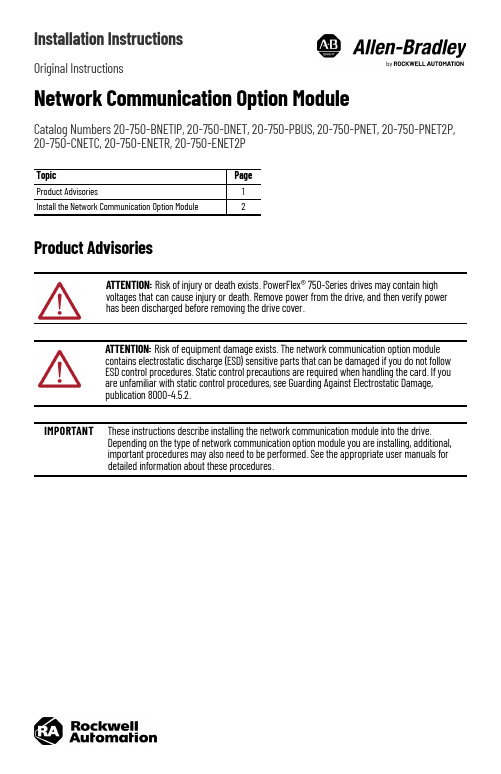
Installation InstructionsOriginal InstructionsNetwork Communication Option ModuleCatalog Numbers 20-750-BNETIP, 20-750-DNET, 20-750-PBUS, 20-750-PNET, 20-750-PNET2P, 20-750-CNETC, 20-750-ENETR, 20-750-ENET2PProduct AdvisoriesTopic Page Product Advisories 1Install the Network Communication Option Module 2ATTENTION: Risk of injury or death exists. PowerFlex® 750-Series drives may contain high voltages that can cause injury or death. Remove power from the drive, and then verify power has been discharged before removing the drive cover.ATTENTION: Risk of equipment damage exists. The network communication option module contains electrostatic discharge (ESD) sensitive parts that can be damaged if you do not follow ESD control procedures. Static control precautions are required when handling the card. If you are unfamiliar with static control procedures, see Guarding Against Electrostatic Damage, publication 8000-4.5.2.IMPORTANT These instructions describe installing the network communication module into the drive. Depending on the type of network communication option module you are installing, additional, important procedures may also need to be performed. See the appropriate user manuals for detailed information about these procedures.Network Communication Option Module Installation InstructionsInstall the Network Communication Option Module1.Remove power from the drive.2.Remove the drive cover and lift up the drive HIM cradle (with or without the HIM installed) to its open position toaccess the drive control pod.3.into the connector.2Rockwell Automation Publication 750COM-IN003A-EN-P - January 2023Rockwell Automation Publication 750COM-IN003A-EN-P - January 20233Network Communication Option Module Installation Instructions4.Remove the lower T15 Torx mounting screw (Detail A) from the network communication module that is to the left of the PROFIBUS or PROFINET network communication module. To remove the captive T15 Torx screw, the module must be removed to back the screw out of the mounting clip.5.Replace the larger T15 Torx screw with the smaller spare T8 Torx mounting screw that was shipped with the PROFIBUS or PROFINET network communication module.6.Tighten both of the option module mounting screws to the pod mounting bracket to properly ground the module to the drive. Tighten both screws to the recommended torque shown in the following figure.IMPORTANT If you are using a PROFIBUS or PROFINET network communication module (20-750-PBUS, 20-750-PNET, or 20-750-PNET2P) with another network communication module that is positioned in the port to the left of the PROFIBUS or PROFINET module, you must replace the T15 Torx screw that holds the other network communication module to the lower mounting bracket.Replace the T15 Torx screw with a spare T8 Torx screw that is included with PROFIBUS and PROFINET modules. Due to its larger size, it is possible for the T15 Torx screw to come into contact with the PROFIBUS / PROFINET cable connector and cause faulty operation. Using the smaller T8 Torx screw helps eliminate this problem.Perform step 4 and step 5 if another network communication module is positioned in the port to the left of the PROFIBUS or PROFINET network communication module; otherwise, disregard these steps and go to step 6.Detail APublication 750COM-IN003A-EN-P - January 2023Copyright © 2023 Rockwell Automation, Inc. All rights reserved. Rockwell Otomasyon Ticaret A.Ş. Kar Plaza İş Merkezi E Blok Kat:6 34752, İçerenköy, İstanbul, Tel: +90 (216) 5698400 EEE Yönetmeli ğine UygundurAllen-Bradley, expanding human possibility, PowerFlex, and Rockwell Automation are trademarks of Rockwell Automation,Inc.Trademarks not belonging to Rockwell Automation are property of their respective companies.Your comments help us serve your documentation needs better. If you have any suggestions on how to improve our content, complete the form at rok.auto/docfeedback .For technical support, visit rok.auto/support.Waste Electrical and Electronic Equipment (WEEE)Rockwell Automation maintains current product environmental compliance information on its website at rok.auto/pec.At the end of life, this equipment should be collected separately from any unsorted municipal waste.Additional ResourcesThese documents contain additional information concerning related products from Rockwell Automation.You can view or download publications at rok.auto/literature .ResourceDescription PowerFlex 20-750-BNETIP BACnet/IP Option Module User Manual, publication 750COM-UM005Provides information about using the PowerFlex 20-750-BNETIP BACnet/IP Option ModulePowerFlex 20-750-CNETC Coaxial ControlNet Option Module User Manual, publication 750COM-UM003Provides information about using the PowerFlex Coaxial ControlNet Option Module PowerFlex 20-750-DNET DeviceNet Option Module User Manual, publication 750COM-UM002Provides information about using the PowerFlex DeviceNet Option Module PowerFlex 20-750-ENETR/ENET2P Dual-port EtherNet/IP Option Module, publication 750COM-UM008Provides information about using the PowerFlex 20-750-ENETR/ENET2P Dual-port EtherNet/IP Option Module PowerFlex 20-750-PBUS Profibus DPV1 Option Module User Manual, publication 750COM-UM004Provides information about using the PowerFlex Profibus DPV1 Option Module PowerFlex PROFINET Single- and Dual-port Option Modules User Manual, publication 750COM-UM007BProvides information about using the PowerFlex PROFINET Single- and Dual-port Option Modules Industrial Automation Wiring and Grounding Guidelines, publication 1770-4.1Provides general guidelines for installing a Rockwell Automation industrial system.Product Certifications website, rok.auto/certifications .Provides declarations of conformity, certificates, and other certification details.。
SymantecNetbackup7.0安装和备份操作指南
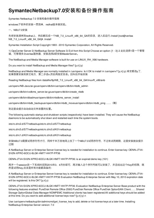
SymantecNetbackup7.0安装和备份操作指南Symantec Netbackup 7.0 安装和备份操作指南windows下软件的安装⼀贯简单,redhat版本做实验。
⼀、NBU7.0安装先将安装源拷到redhat上,然后解压成⼀个NB_7.0_LinuxR_x86_64_GA的⽬录,进⼊后运⾏./install [root@veritasNB_7.0_LinuxR_x86_64_GA]# ./installSymantec Installation Script Copyright 1993 - 2010 Symantec Corporation, All Rights Reserved.1) OpsCenter Server 2) NetBackup Server Software 3) Exit from this Script Choose an option: [1 - 3]: 2 此处选择1是⼀个管理端,可管理多台veritas服务器,安装选择2即安装MasterServer。
The NetBackup and Media Manager software is built for use on LINUX_RH_X86 hardware.Do you want to install NetBackup and Media Manager files? [y,n] (y)NetBackup and Media Manager are normally installed in /usr/openv. Is it OK to install in /usr/openv? [y,n] (y) 肯定都选y了,如果想要安装到其它地⽅,第⼆步选n,然后再指定⽬录。
回车后开始安装Reading NetBackup files from /datafile/ftp/NB_7.0_LinuxR_x86_64_GA/linuxR_x86/anbusr/openv/NB-Java.tar.gzusr/openv/db/bin/usr/openv/db/bin/nbdb_adminusr/openv/db/bin/vxdbms_server.tar.gzusr/openv/db/bin/create_nbdbusr/openv/db/bin/dbadmusr/openv/db/bin/nbdbms_server_installusr/openv/db/bin/nbdb_backupusr/openv/db/bin/nbdb_moveusr/openv/db/bin/nbdb_ping ……(略)到这⾥会提⽰⾃动启动⽂件放置的位置。
Symantec Netbackup 7.0 安装和备份操作指南
Symantec Netbackup 7.0 安装和备份操作指南windows下软件的安装一贯简单,redhat版本做实验。
一、NBU7.0安装先将安装源拷到redhat上,然后解压成一个NB_7.0_LinuxR_x86_64_GA的目录,进入后运行./install [root@veritas NB_7.0_LinuxR_x86_64_GA]# ./installSymantec Installation Script Copyright 1993 - 2010 Symantec Corporation, All Rights Reserved.1) OpsCenter Server 2) NetBackup Server Software 3) Exit from this Script Choose an option: [1 - 3]: 2 此处选择1是一个管理端,可管理多台veritas服务器,安装选择2即安装MasterServer。
The NetBackup and Media Manager software is built for use on LINUX_RH_X86 hardware.Do you want to install NetBackup and Media Manager files? [y,n] (y)NetBackup and Media Manager are normally installed in /usr/openv. Is it OK to install in /usr/openv? [y,n] (y) 肯定都选y了,如果想要安装到其它地方,第二步选n,然后再指定目录。
回车后开始安装Reading NetBackup files from /datafile/ftp/NB_7.0_LinuxR_x86_64_GA/linuxR_x86/anbusr/openv/NB-Java.tar.gzusr/openv/db/bin/usr/openv/db/bin/nbdb_adminusr/openv/db/bin/vxdbms_server.tar.gzusr/openv/db/bin/create_nbdbusr/openv/db/bin/dbadmusr/openv/db/bin/nbdbms_server_installusr/openv/db/bin/nbdb_backupusr/openv/db/bin/nbdb_moveusr/openv/db/bin/nbdb_ping ……(略)到这里会提示自动启动文件放置的位置。
简述海外台站RouterBOARD 750的安装及登陆过程
简述海外台站RouterBOARD 750的安装及登陆过程作者:李东杰来源:《科技传播》2016年第06期摘要本文通过对海外台站使用RouterBOARD 750进行组网的实例,来学习和了解RouterBOARD的基础知识及RouterBOARD 750的基本使用方法,通过对RouterBOARD的更深层次的认知与扩展,进一步来学习RouterOS(路由操作系统)的基础知识,通过操控WinBox控制台的图形界面软件来管理和配置RouterOS系统,进而来完成对RouterBOARD 750硬路由的管理,本文只是简单的概述了RouterBOARD 750的安装过程及配置和管理RouterOS系统的WinBox软件的初始登录过程。
关键词 RouterBOARD;RouterOS;WinBox控制台;图形用户接口(GUI)中图分类号 G2 文献标识码 A 文章编号 1674-6708(2016)159-0078-01由于海外台站所在驻地国家的互联网技术较为落后,台站内一直在使用微波进行数据信息的传输,数据“丢包”十分严重,且在恶劣天气下数据传送效率极低,基于以上的原因,经研究后,我们特别申请安装了光纤网络,以减少由于恶劣气候、电波干扰等不利因素而造成的数据传输速率低下及数据传送中突然中断等现象的发生。
由于这次是对海外工作人员职工宿舍的基础网络进行安装,所以相对来说比较简单,仅是为了满足职工的文化生活需要,如浏览网页、检索信息、视频联络等基本上网需求的应用,因此,针对这种情况,我们配备了一套十分简单相对容易的计算机网络架构,此文就不多说了,在这里我们主要讲述是Mikrotik RouterBOARD750的安装情况与所处位置及对Mikrotik RouterOS(路由操作系统)进行配置的过程。
在叙述之前,我们先来了解一下RouterBOARD与RouterOS方面的知识,这两款产品都是由东欧小国拉脱维亚的Mikrotik公司(Mikrotikls SIA)开发的。
适用于 Microsoft System Center 的 OpenManage Integrati
适用于 Microsoft System Center 的 OpenManage Integration 7.0 版安装指南注、小心和警告注: “注”表示帮助您更好地使用该产品的重要信息。
小心: “小心”表示可能会损坏硬件或导致数据丢失,并说明如何避免此类问题。
警告: “警告”表示可能会造成财产损失、人身伤害甚至死亡。
版权所有© 2009 - 2017 Dell Inc. 或其子公司。
保留所有权利。
Dell、EMC 和其他商标均为 Dell Inc. 或其附属公司的商标。
其他商标均为其各自所有者的商标。
2017 - 08Rev. A001 简介 (5)2 关于 OMIMSSC 组件 (6)3 安装 OMIMSSC 控制台扩展计划 (7)计划在 SCCM 上安装 OMIMSSC (7)在 SCVMM 上安装 OMIMSSC 计划 (7)4 OMIMSSC 的系统要求 (8)帐户权限 (8)OMIMSSC 的通用系统要求 (8)适用于 SCCM 的 OMIMSSC 控制台扩展的系统要求 (10)验证权限以使用适用于 SCCM 的 OMIMSSC 控制台扩展 (10)适用于 SCVMM 的 OMIMSSC 控制台扩展的系统要求 (12)网络要求 (12)5 安装、配置和维护 OMIMSSC (14)从 web 下载OMIMSSC (14)设置设备 (14)启动管理员门户以下载 OMIMSSC 组件 (16)安装 IG for OMIMSSC (16)安装适用于 SCCM 的 OMIMSSC 控制台扩展 (18)安装 SCVMM 的OMIMSSC 控制台扩展 (18)注册控制台 (19)启动适用于 SCCM 的 OMIMSSC 控制台扩展 (19)启动适用于 SCVMM 的 OMIMSSC 控制台扩展 (19)导入 SCVMM 的 OMIMSSC 控制台扩展 (20)启动适用于 SCVMM 的 OMIMSSC 控制台扩展 (20)6 管理 OMIMSSC 及其组件 (21)查看设备详情 (21)OMIMSSC 用户管理 (21)查看或刷新已注册的控制台 (21)修复或修改安装程序和帐户 (21)修复适用于 SCCM 的 OMIMSSC 控制台扩展 (22)修复适用于 SCVMM 的 OMIMSSC 控制台扩展 (22)修复 OMIMSSC IG (22)修改 IG 和 SCCM 或 SCVMM 帐户 (22)卸载 OMIMSSC (23)注销 OMIMSSC 控制台 (23)目录3卸载 OMIMSSC IG (24)卸载适用于 SCCM 的 OMIMSSC 控制台扩展 (24)卸载适用于 SCVMM 的 OMIMSSC 控制台扩展 (24)其他卸载步骤 (24)移除设备 VM (25)迁移或升级旧版适用于Configuration Manager 的 DLCI 和适用于 SCVMM 的 DLCI (25)升级 OMIMSSC (25)关于服务包更新 (25)升级 IG (28)升级适用于 SCVMM 的 OMIMSSC 控制台扩展 (28)7 故障排除 (29)删除适用于 SCVMM 的 OMIMSSC 控制台扩展中的帐户 (29)与 ADK 的设备兼容性问题 (29)设备和 Integration Gateway 之间的连接丢失 (29)在更新 SCVMM R2 后访问控制台插件时出错 (30)通过 Mozilla Firefox 浏览器访问 OMIMSSC 管理员门户时出现错误消息 (30)无法连接 OMIMSSC 设备 (30)IP 地址未分配至设备 (30)访问 SCVMM 不需要权限 (30)将服务器添加到 Active Directory 时发生 SCVMM 错误 21119 (31)注册失败 (31)8 访问 Dell EMC 支持站点上的文档 (32)联系 Dell (32)4目录简介OpenManage Integration for Microsoft System Center (OMIMSSC) 可集成到 System Center 产品套件,通过使用带生命周期控制器(LC) 的集成戴尔远程访问控制器 (iDRAC) 支持 Dell EMC 服务器的完整生命周期管理。
VMWare Horizon7平台安装指南
VMWare Horizon 7 安装指南VMware Horizon 7 7.5目录Horizon 7 安装61 服务器组件的系统要求7Horizon 连接服务器的要求7Horizon Administrator 要求9View Composer 的要求92 客户机操作系统的系统要求12Horizon Agent 支持的操作系统12独立Horizon Persona Management 支持的操作系统13远程显示协议和软件支持133 在IPv6 环境中安装Horizon 7 19在IPv6 环境中设置Horizon 7 19IPv6 环境中支持的vSphere 数据库和Active Directory 版本20IPv6 环境中Horizon 7 Server 支持的操作系统20IPv6 环境中桌面和RDS 主机支持的Windows 操作系统21IPv6 环境中支持的客户端21IPv6 环境中支持的远程协议21IPv6 环境中支持的身份验证类型22IPv6 环境中其他受支持的功能224 以FIPS 模式安装Horizon 7 25以FIPS 模式安装Horizon 7 的概述25FIPS 模式的系统要求265 准备Active Directory 27配置域和信任关系27为远程桌面创建OU 28为Kiosk 模式客户端帐户创建组织单位和组29创建用户组29为vCenter Server 创建用户帐户29为独立的View Composer Server 创建用户帐户29为View Composer AD 操作创建用户帐户30为即时克隆操作创建用户帐户31配置受限制的组策略31使用Horizon 7 组策略管理模板文件32为智能卡身份验证准备Active Directory 32在SSL/TLS 中禁用弱密码356 安装View Composer 37准备View Composer 数据库37为View Composer 配置SSL 证书45安装View Composer 服务45对从View Composer 进行的vCenter 和ESXi 连接启用TLSv1.0 47为View Composer 配置基础架构487 安装Horizon 连接服务器50安装Horizon 连接服务器软件50安装Horizon 连接服务器的前提条件51使用新配置安装Horizon 连接服务器51安装Horizon 连接服务器副本实例58配置安全服务器的配对密码64安装安全服务器65Unified Access Gateway 设备优于VPN 的方面72Horizon 连接服务器的防火墙规则73使用备份配置重新安装Horizon 连接服务器74Microsoft Windows Installer 命令行选项76使用MSI 命令行选项静默卸载Horizon 7 组件778 为Horizon 7 Server 配置TLS 证书80了解Horizon 7 Server 的TLS 证书80TLS 证书设置任务概述82获取CA 签发的TLS 证书83配置Horizon 连接服务器、安全服务器或View Composer 以使用新TLS 证书84配置客户端端点以信任根证书和中间证书89为服务器证书配置证书撤消检查91配置PCoIP 安全网关以使用新TLS 证书92将Horizon Administrator 设置为信任vCenter Server 或View Composer 证书96使用CA 签发的TLS 证书的优势96Horizon 连接服务器和安全服务器上的证书问题故障排除969 首次配置Horizon 7 98为vCenter Server、View Composer 和即时克隆配置用户帐户98首次配置Horizon 连接服务器103配置Horizon Client 连接114替换Horizon 7 服务的默认端口121调整Windows Server 设置以支持您的部署12710 配置事件报告129为Horizon 7 事件添加数据库和数据库用户129为事件报告准备SQL Server 数据库130配置事件数据库130为Syslog 服务器配置事件日志记录132Horizon 7 安装《Horizon 7 安装指南》介绍如何安装VMware Horizon® 7 服务器和客户端组件。
CentOS 7安装配置
C e n t O S7.0系统安装配置图解教程2014年07月08日 ⁄C e n t O S⁄评论数 5⁄被围观 5,444次+说明:截止目前C e n t O S7.x最新版本为C e n t O S7.0,下面介绍C e n t O S7.0的具体安装配置过程服务器相关设置如下:操作系统:C e n t O S7.064位I P地址:192.168.21.128网关:192.168.21.2D N S:8.8.8.88.8.4.4备注:生产服务器如果是大内存(4G以上内存),建议安装64位版本C e n t O S-7.0-1406-x86_64-D V D.i s o一、安装C e n t O S7.0成功引导系统后,会出现下面的界面界面说明:I n s t a l l C e n t O S7安装C e n t O S7T e s t t h i s me d i a& i n s t a l l C e n t O S7测试安装文件并安装C e n t O S7 T r o u b l e s h o o t i n g修复故障这里选择第一项,安装C e n t O S7,回车,进入下面的界面选择语言:中文-简体中文(中国) #正式生产服务器建议安装英文版本继续选择-系统-安装位置,进入磁盘分区界面选择-其它存储选项-分区-我要配置分区,点左上角的“完成”,进入下面的界面系统运维 w w w.o s y u n w e i.c o m 温馨提醒:q i h a n g01原创内容©版权所有,转载请注明出处及原文链 分区前先规划好s w a p#交换分区,一般设置为内存的2倍/#剩余所有空间备注:生产服务器建议单独再划分一个/d a t a分区存放数据点左下角的“+”号挂载点:s w a p期望容量:2048添加挂载点,如下图所示系统运维 w w w.o s y u n w e i.c o m 温馨提醒:q i h a n g01原创内容©版权所有,转载请注明出处及原文链 继续点左下角的“+”号挂载点:/期望容量:18.43G B#剩余所有空间添加挂载点,如下图所示点左上角的“完成”,进入下面的界面接受更改,进入下面的界面进入下面的界面选择-用户设置-R O O T密码,进入下面的界面如果密码长度少于8位,会提示要按“完成”两次来确认,安装继续安装完成之后,会进入下面的界面点重启系统重新启动进入登录界面账号输入r o o t回车再输入上面设置的r o o t密码回车系统登录成功二、设置I P地址、网关D N S说明:C e n t O S7.0默认安装好之后是没有自动开启网络连接的!c d/e t c/s y s c o n f i g/n e t w o r k-s c r i p t s/#进入网络配置文件目录v i i f c f g-e n o16777736#编辑配置文件,添加修改以下内容H WA D D R=00:0C:29:8D:24:73T Y P E=E t h e r n e tB O O T P R O T O=s t a t i c#启用静态I P地址D E F R O U T E=y e sP E E R D N S=y e sP E E R R O U T E S=y e sI P V4_F A I L U R E_F A T A L=n oI P V6I N I T=y e sI P V6_A U T O C O N F=y e sI P V6_D E F R O U T E=y e sI P V6_P E E R D N S=y e sI P V6_P E E R R O U T E S=y e sI P V6_F A I L U R E_F A T A L=n oN A ME=e n o16777736U U I D=a e0965e7-22b9-45a a-8e c9-3f0a20a85d11 O N B O O T=y e s#开启自动启用网络连接I P A D D R0=192.168.21.128#设置I P地址P R E F I X O0=24#设置子网掩码G A T E WA Y0=192.168.21.2#设置网关D N S1=8.8.8.8#设置主D N SD N S2=8.8.4.4#设置备D N S:w q!#保存退出s e r v i c e n e t w o r k r e s t a r t#重启网络p i n g w w w.b a i d u.c o m #测试网络是否正常i p a d d r#查看I P地址三、设置主机名为w w wh o s t n a me w w w#设置主机名为w w wv i/e t c/h o s t n a me#编辑配置文件w w w#修改l o c a l h o s t.l o c a l d o ma i n为w w w:w q!#保存退出v i/e t c/h o s t s#编辑配置文件127.0.0.1l o c a l h o s t w w w#修改l o c a l h o s t.l o c a l d o ma i n为w w w :w q!#保存退出s h u t d o w n-r n o w#重启系统至此,C e n t O S7.0系统安装配置图解教程完成!。
- 1、下载文档前请自行甄别文档内容的完整性,平台不提供额外的编辑、内容补充、找答案等附加服务。
- 2、"仅部分预览"的文档,不可在线预览部分如存在完整性等问题,可反馈申请退款(可完整预览的文档不适用该条件!)。
- 3、如文档侵犯您的权益,请联系客服反馈,我们会尽快为您处理(人工客服工作时间:9:00-18:30)。
NetStor® iSUM 750 快速安装指南
0
北京同有飞骥科技股份有限公司
NetStor® iSUM 750 快速安装指南
文档修订记录
版本号 V1.0
V7.0
日期 2010-08-04
2011-01-24
描述说明 初始版本 公司名称变更,产品工程统一切换; 取消产品“DS 系列”命名规则
NetStor® iSUM 750 快速安装指南
2.5.4 创建 RAID.......................................................................................................... 25 2.5.5 创建逻辑卷 ....................................................................................................... 28 2.5.6 创建分区 ........................................................................................................... 32 2.5.7 创建映像 ........................................................................................................... 37 2.5.8 查询分区 ........................................................................................................... 40 2.5.9 对新分区初始化 ................................................................................................ 41 2.5.10 读写数据 .......................................................................................................... 41 2.6 扩展柜的连接 ........................................................................................................... 41 2.6.1 iSUM750 扩展柜的外观.................................................................................... 41 2.6.2 扩展柜指示灯 .................................................................................................... 42 2.6.3 扩展柜设置开关 ................................................................................................ 43 2.6.4 设置磁盘模式 ................................................................................................... 43 2.6.5 连接图 ................................................................................................................ 45 2.7 技术支持 ................................................................................................................... 46 2.7.1 联系技术支持部门............................................................................................ 46 2.7.2 技术支持服务方式............................................................................................ 46
用途的商品性和适用性的隐含担保。北京同有飞骥科技股份有限公司对本材 料中可能出现的任何错误都不承担任何责任。 本公司对文件中的资讯有最终解释权,如有变更,恕不另行通知。 手册中涉及第三方的品牌和名称是他们相应的拥有者的产权。 NetStor®为同有公司的注册商标。
III
NetStor® iSUM 750 快速安装指南
2.1 打开 iSUM 750 包装 .................................................................................................. 6 2.2 安装导轨...................................................................................................................... 7 2.3 安装 iSUM750 磁盘阵列 ...........................................................................................11
1.3 安全规范要求 ............................................................................................................. 3
第 2 章 安装步骤......................................................................... 6
II
NetStor® iSUM 750 快速安装指南
声明
北京同有飞骥科技股份有限公司 2011 年版权所有。 如未事先得到北京同有飞骥科技股份有限公司的任何书面许可,手册中任何
部分都不得进行复制,或以任何形式、任何手段进行转载。 北京同有飞骥科技股份有限公司对本手册未作任何形式的担保,包括对具体
目录
第 1 章 警告和注意事项............................................................. 1
1.1 警告............................................................................................................................. 1 避免受伤 ....................................................................................................................... 1 系统供电 ....................................................................................................................... 1
2.3.1 安装 HBA 卡 ......................................................................................................11 2.3.2 安装磁盘 .............................................................................................................11 2.3.3 连接电源 ............................................................................................................ 14 2.3.4 HBA 卡与主机通道的连接 ............................................................................... 15 2.3.5 连接管理链路 ................................................................................................... 15 2.3.6 设置磁盘模式 .................................................................................................... 16 2.4 启动磁盘阵列............................................................................................................ 17 2.4.1 开启服务器 ........................................................................................................ 17 2.4.2 开启磁盘阵列电源............................................................................................. 17 2.4.3 磁盘阵列启动完成............................................................................................. 18 2.5 配置磁盘阵列 ........................................................................................................... 18 2.5.1 安装 SANManager 软件 .................................................................................... 19 2.5.2 进入管理界面 ................................................................................................... 20 2.5.3 查看磁盘信息 .................................................................................................... 24 IV