US-015产品介绍V2.0
US-015产品介绍
US-015超声波测距模块1.概述US-015是目前市场上分辨率最高,重复测量一致性最好的超声波测距模块;US-015的分辨率高于1mm,可达,测距精度高;重复测量一致性好,测距稳定可靠。
US-015超声波测距模块可实现2cm~4m的非接触测距功能,供电电压为5V,工作电流为,支持GPIO通信模式,工作稳定可靠。
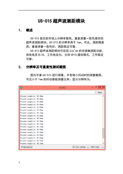
2.分辨率及可重复性测试截图图为手拿US-015进行测量,手有微小抖动时的测量截图,可见小于1mm的抖动都能测量出来;显示分辨率为。
图:手持US-015微小抖动测量截图图为将US-015固定后,经过一段时间测量后的截图,可见重复测量一致性好。
显示分辨率为图:重复测量截图图及图所用例程请参考后文附录。
3.主要技术参数电气参数US-015超声波测距模块工作电压DC 5V工作电流工作温度0~+70度输出方式GPIO感应角度小于15度探测距离2cm-400cm探测精度+1%分辨率高于1mm(可达)4.本模块实物图及尺寸本模块如图和图所示:图: US-015正面图图:US-015背面图本模块的尺寸:45mm*20mm*。
板上有两个半径为1mm的机械孔,如图所示:图:US-015尺寸图5.接口说明本模块有一个接口:4 Pin供电及通信接口。
4 Pin接口为间距的弯排针,如图所示:图:4 Pin接口从左到右依次编号1,2,3,4。
它们的定义如下:1号Pin:接VCC电源(直流5V)。
2号Pin:接外部电路的Trig端,向此管脚输入一个10uS以上的高电平,可触发模块测距。
3号Pin:接外部电路的Echo端,当测距结束时,此管脚会输出一个高电平,电平宽度为超声波往返时间之和。
4号Pin:接外部电路的地。
6.测距工作原理模块测距的时序如图所示:10US高电平触发信号发射探头发出信号输出回响信号循环发出8个40KHZ脉冲脉冲宽度为超声波往返时间之和图:US-015测距时序图图表明:只需要在Trig管脚输入一个10US以上的高电平,系统便可发出8个40KHZ的超声波脉冲,然后检测回波信号。
AXOS系列产品简介说明书

EMC TESTING PRODUCT OVERVIEWCUSTOMER BASE FOR EMC TESTINGCOMPACT TESTERThe AXOS is an ultra-compact immunity tester that performs all the most commonly used transient immunity tests, including Surge, EFT, Dips/Interrupts, AC/Surge Magnetic Field, Ring Wave and Telecom Surge. Full Compliance and Pre-Compliance tests are performed to meet the requirements of a wide variety of transient immunity standards, including IEC 61000-4-x “CE Mark” Basic standards, IEC 60601 for Medical equipment, and many other IEC, ANSI, ITU, UL and specific product standards.P C D 126AD E C 5D E C 6D E C 7I P 4BP A T 50 AP A T 1000Surge 1.2/50 & 8/20, 5.0kV EFT / Burst 5.0kV Dips & InterruptsSurge magnetic field 61000-4-9Insulation testing 1.2/50, 15kV 3-phase surge 32A 3-phase surge 100A 3-phase EFT/Burst 32A 3-phase EFT/Burst 100ACDNs symmetrical data & control lines CDNs asymmetrical data & control lines Capacitive coupling clampsELECTROSTATIC DISCHARGEThe ONYX simulators by HAEFELY HIPOTRONICS have been specially designed to meet all latest international standards, including IEC61000-4-2 Ed. 2 and are the most ergonomic battery and AC power operated 30kV guns on the market. 16kV and 30kV models available, along with a complete range of accessories that ensure a complete ESD test setup (verification equipment, test tables, coupling planes etc).FEATURESSTANDARDS a 16kV and 30kV models a Touch screen operation a Modulara Automatic polarity switching a Remote control software a Remote triggera Bleed-of Functionalitya Lightweight and portable design a Battery and AC operation a Environmental monitoring a Onboard LED EUT light a Smart key functionsa Contact discharge current flow detection a Self-test functiona IEC 61000-4-2 Ed. 2a IEC613402-1/-2a IEC 801-2a IEC 60571a EN 50155 a ANSI C63.16a ISO 10605a ISO 14304a ITU-T K20a MIL-STD-1512/-1514/-750D/-883a RTCA/DO-160a JEDEC 22-A114A a GR-78/1089-COREThe self test function is a built-in self test routine which checks the HV supply, the impulse capacitor, the HV discharge relays, and the insulation of the entire HV circuitry.Bleed-off functionalityThe so called bleed-off functionality of the ONYX simulator ensures via an integrated relay that the EUT is completely discharged before the next ESD pulse is initiated. This functionality ensures a maximum of test accuracy to the user without the need for a discharge brush.Smart Key OperationThe smart key button is integrated at the upper part of the discharge trigger and has various functions which are defined by the user, enabling you to run a sequence of events according to your testing requirements, and simplify test procedures.The functions include user defined discharge voltages steps, sweep voltage, On/Off LED light, Polarity Switching, control and report function.Compliance & ModularityThe design is based on the requirements of all latest international standards, including the latest IEC 61000-4-2 Ed. 2. R/C module values are available from 50-5000 Ohms and 50-1000pF , which enables users to fully test according to many international standards.Contact Discharge Current Flow Detection & Self T estThe unique NO CONTACT detection circuit function continuously monitors whether ESD pulses are discharged to the EUT , ensures users the test was successful and prevents incorrect test results.ONYX 16n16kV Electrostatic Discharge Simulatorn16kV Air & Contact Dischargen150pF/330Ω standard discharge networkn Exchangeable RC modules to meet variousstandard requirements (IEC, ISO, ANSI, MIL)n Ergonomic design and operation (touch screen) n Rechargeable battery or mains operatedn Smart key functionsn Automatic polarity switchingn Remote triggern Self test functionn Includes: Light rigid carrying case, contact and air discharge tips, mains supply, 2 x rechargeable battery pack with chargerSOFTWAREWhy should you use software to perform ESD tests?Because it makes your life easier and helps to make tests more reliable and reproducible. Benefitsn Windows XP, Windows Vista and Windows 7 compatibilityn Support of USB and optical USB interfacesn Easy-to-use and intuitive creator for test plans and test proceduresn Enhanced and highly flexible reporting capabilitiesn Up-to-date design and navigationn Intuitive operationn Independent test station n High end componentsn Very high result accuracy and precision n Higher voltage level of 7.3kV n Spike frequency up to 110 kHz n IEC/EN61000-4-4 Ed. 3n Unique windows based control and reporting software n Distinctive safety features n Ideal for over testingn Multi-test stationn Covers EFT/Burst, Surge, Dips & Interrupts, Magnetic Field, and Insulation Tests n 5.0kV EFT/Burstn Fully meets all latest standards including IEC/EN61000-4-4 Ed. 3n Ideal for pre-compliance testing and CE markingNOTE: Please refer to the COMPACT section on page 3 for details.All our EFT/Burst generators are 100% compliant to the latest standards, including IEC/EN 61000-4-4 Ed. 3, which is mandatory from April 2012.DISTINCTIVE FEATURESSTAND-ALONECOMPACTEFT/BURSTBursts or EFTs (Electrical Fast Transients) are caused by operation of electro-mechanical switches, motors and distribution switch-gear connected to the power distribution network. A typical burst consists of a large number of recurring impulses at high frequency for a short time period.V 90%50%10%FlexibilityDepending on the actual testing requirements, we offer our customers the choice between stand alone and compact testing equipment.Stand alone equipment allow users to test at levels higher than what is usually required within the standards, making such testers ideal for over-testing purposes.Compact solutions allow users to not only cover the latest eft/burst requirements, but also to carry out surge, dips & interrupts, magnetic field, and insulation tests.EFT SOLUTIONSn 5kV Burst Test Systemn Built according to IEC/EN 61000-4-4 Ed. 2 & 3 as well as to ANSI/IEEE C62.41/45 and C37.90.1n Impulse voltage up to 5kVn Frequency range from 1Hz to 1MHzn IEC, random, continuous and real burst mode n Ramp functionsn Integrated automated single-phase CDN for AC and DC up to 16A EUT mains current n Burst parameters editable during testingn 7.3kV Burst Test Systemn Built according to IEC/EN 61000-4-4 Ed. 2 & 3 as well as to ANSI/IEEE C62.41/45 and C37.90.1n Impulse voltage up to 7.3kVn Frequency range from 1Hz to 100kHzn IEC, random, continuous and real burst mode n Ramp functionsn Integrated automated single-phase CDN for AC and DC up to 16A EUT mains current n Burst parameters editable during testingAXOS SERIESPEFT 8010MANUAL 32A THREE-PHASE COUPLING-DECOUPLING NETWORK FOR EFT TESTING100A THREE-PHASE COUPLING/DECOUPLING NET-WORK FOR EFT TESTINGFP-EFT 32MFP-EFT 100M2n Built according to IEC/EN 61000-4-4 Ed. 2 & 3 and ANSI C62.41/45n Superposition of EFT impulses onto three- phase power lines and DC power lines n 8kV maximum impulse voltage n EUT voltage up to 690V/400V ACn EUT mains current up to 100A per phase n Manual coupling path switchingnSynchronization with power supply possiblen Built according to IEC/EN 61000-4-4 Ed. 2 & 3 as well as to ANSI C62.41/45n Superposition of EFT impulses onto three- phase power lines and DC power linesn 8kV maximum impulse voltagen EUT mains voltage up to 690V/400V AC, 110V DC n EUT mains current up to 32A per phase n Synchronization with power supply possible nEUT over-current protectionEFT VERIFICATION SETWAVEFORM VERIFICATION SETOPTIONSn Built according to IEC/EN 61000-4-4 Ed. 2 & 3 and ANSI C37.90.1n 40mm maximum cable size n Up to 8kV impulse voltage n Handy carrying handlen Optional transducer plate for clamp calibration/ verificationn Built according to IEC/EN 61000-4-4 Ed. 2 & 3n For verification/calibration of EFT generators (PEFT 4010, PEFT 8010, AXOS Series)n Combined 50Ω load, 54 dB attenuator n Combined 1 k Ω load, 60 dB attenuator n Required cables includedn Supplied with detailed application noten IEEE 488 interface optionn Three phase verification adaptersn Warning lamps and emergency switches n Fibre optic links (EUT fail)n Test tablesn Dedicated software WinFEAT&R n Upgrade kits for older modelsnReal burst functional extensionn Optical decoupling fibre optic links (RS232)n AC and DC adaptersn Near field test probes (E&H)n Vertical operation stands VOSSURGE - TRANSIENT / LIGHTNINGPRODUCTS AND APPLICATIONSStand-alone, compact, and modular Surge impulse generators are available up to 30kV , which cover a range of EMC surge tests including the classical IEC defined “Combination Wave“ 1.2/50 & 8/20, “Hybrid waves“ defined for telecommunications testing, 10/700, ring wave, damped oscillating wave, magnetic field, and many more.Typical standard applications include IEC, EN and ANSI for power line testing, FCC, Bellcore, ITU and ETSI for telecom testing.Our modular Surge Platform can also be used for product safety testing to UL standards and also ITE requirements. A wide range of accessories from single and three phase CDNs up to 100A and telecoms coupling units, make these systems the most modular and flexible test equipment on themarket.32A THREE-PHASE COUPLING/DECOUPLING NETWORK FOR SURGE TESTINGFP-COMB 32n Built according to IEC/EN 61000-4-5 Ed. 2 & 3n EUT voltage up to 480Vn EUT current up to 32A per phasenTest level max. 7.0kV / 3.5kA n Fully automatic test routinesn Automatic synch source switching n Test object power line bypass mode n Test object overcurrent protection15KV VOLTAGE SURGE GENERATORPS 1500n Built according to IEC/EN 60065,IEC/EN 60950-1 and UL 1414n Impulse voltage up to 15kV n Up to 24 discharges per minute n Positive and Negative Polarity n External trigger inputn Automatic selection of 4M Ω/100 M Ω parallel resistor n Impulse voltage monitor n Includes test pistol n Flash measurement n Insulation/safety testing n Component testingn Small and compact design30KV SURGE TEST SYSTEMSINGLE-PHASE COUPLING/DECOUPLING NETWORKFOR SURGE TESTING UP TO 30KV / 15KAPSURGE 30.2FP-SURGE 3010n Single-phase EUT powering n EUT mains voltage up to 480V n EUT mains current up to 10An Manual selection of coupling path and coupling capacitor n Test level up to 15kV/30kA n EUT overcurrent protection n Large integrated test cabinetn Built according to IEC/EN61000-4-5, IEC/EN 61010, IEC/EN 61643-1 and ANSI C62.41/45n Impulse voltage up to 30kV (combination wave)n Impulse current up to 30kA (8/20 µs)n Combination wave (1.2/50 µs & 8/20 µs)n 8/20 µs, 10/350 µs, 10/1000 µs current pulse n Impulse voltage & current measurement n Automatic polarity switching n Integrated test cabinetPIM 100PIM 110COMBINATION WAVE IMPULSE MODULERING WAVE IMPULSE MODULEn Built according to IEC/EN 61000-4-5 Ed. 1 & 2 and ANSI C62.41/45n 1.2/50 µs open circuit up to 7.4kV n 8/20 µs short circuit up to 3.7kAnImpulse voltage and current monitors n *1° Phase synchronizationn Reliable semiconductor HV-switchn Positive, negative and alternating polarity n Up to 12 pulses per minuten Built according to IEC/EN 61000-4-12 and ANSI C62.41/45n 100 kHz frequency, 0.5 µs rise time n Imp. voltage up to 7.8kV / 12 Ω, 30 Ω and 200 Ωn Impulse voltage and current monitors n *1° phase synchronizationn Positive, negative and alternating polarity n Up to 12 pulses per minuten Reliable semiconductor HV-switch100A THREE-PHASE COUPLING/DECOUPLING NETWORKMANUAL SURGE COUPLING UNIT FOR SYMMETRICAL DATA AND CONTROL LINESPCD 121n Built according to IEC/EN 61000-4-5 Ed. 2 Fig. 14 & Ed. 3 Fig. 10n Coupling of Combination Wave impulses n Up to 2 pairs / 4 wires can be testedn Serial resistors included, 4 x 40/80/160 Ohm n Gas arrestors and Avalanche Breakdown Diodes coupling elements included n Can be used with any surge generator n Impulse voltage up to 6.6kVnSignal Bandwidth up to > 10 MHzPCD 122MANUAL SURGE COUPLING UNIT FOR SYMMETRICAL DATA AND CONTROL LINESn Built according to IEC/EN 61000-4-5 Ed. 2 Fig. 14 & Ed. 3 Fig. 10n Coupling of 10/700 µs impulsesn Up to 2 pairs / 4 wires can be testedn Serial resistors included, 4 x 25/50/100 Ohmn Gas arrestors and Avalanche Breakdown Diodes coupling elements included n Can be used with any surge generator n Impulse voltage up to 6.6kVn Signal Bandwidth up to > 10 MHz.MANUAL SURGE COUPLING/DECOUPLING UNIT FOR DATA AND SURGE DECOUPLING UNIT FOR SYMMETRICAL DATAn Signal Bandwidth up to some 10MHzDEC 7SURGE DECOUPLING UNIT FOR ASYMMETRICAL DATA AND CONTROL LINESn Built according to:IEC/EN 61000-4-5 Ed. 2 Fig. 11, 12 & 13 & Ed. 3 Fig. 9IEC 61000-4-12:1995 Fig. 9, 10, 13 & 14 Array n Decoupling of Combination wave impulsesn Decoupling of Ring Wave (100kHz) impulsesn Up to four wire can be tested simultaneousn Decoupling: Inductors 20mH not compensatedn Protection elements are Varistors and Breakdown avalanche diodesn Can be used with any surge generatorn Impulse voltage up to 6.6kVn Signal Bandwidth up to some 100 HzLOW ENERGY IMPULSE TRANSFORMER FOR INSULATION TESTING NETWORK FOR SURGE PLATFORMPOWER FREQUENCY MAGNETIC FIELD TEST SYSTEMMAG 1000n Built according to IEC/EN 61000-4-8n 1m x 1m antenna included w/ stand n Up to 1100A/m field strength n Horizontal and Vertical testingn Continuous and short duration testing n Built in power supply at 50/60Hz n Simple interfaceMSURGE-APULSE MAGNETIC FIELD TEST SYSTEMnBuilt according to IEC/EN 61000-4-9n 8/20µs magnetic field wave shape n Up to 3000A/m field strength n Sturdy constructionn Horizontal and vertical testingn Control from HAEFEL Y surge generators n Single turn coil with 1m x 1m square area n Optional 2m x 2.6m magnetic coilDip: decrease of the mains VoltageSOFTWAREThe WinFEAT&R software is the latest generation of control and reporting software, based on a modern Drag and Drop concept. With such ease of use, even users with minimum technical experience will be carrying out tests in no time.This unique software allows users to run user specified or pre-defined tests according to the latest standards, and monitors and displays real time output current and voltage values.Communication between software and oscilloscope monitoring allows screenshots to be added to the test report.The software runs up to Windows 7 and is compatible with all stand-alone HAEFEL Y HIPOTRONICS test generators.FEATURESn Control and reporting for stand-alone EFT/Burst, Surge, Dips& Interrupts generators.n Drag and Drop applicationn User defined tests can be added and pre-defined tests arealready included (according to the standards).n Output Current/Voltage monitoring during test.n EUT supervision (max/min V/I levels).n User friendly, designed for use by users with minimumtechnical experience.n Automatic synchronization between software and PC.n Test setup uploaded to Oscilloscope.n User defined test report with oscilloscope screenshotoption.n Fully compatible with Windows 7 (32-bit/64-bit)A u g u s t 2013EuropeChinaNorth America Haefely T est AG Haefely T est AG Representative Beijing OfficeHipotronics, Inc.Birsstrasse 300 8-1-602, Fortune Street1650 Route 22 N 4052 Basel No. 67, Chaoyang Road, Chaoyang DistrictBrewster, NY 10509SwitzerlandBeijing, China 100025United States☎ + 41 61 373 4111 ☎ +86 10 8578 8099 ☎ +1 845 230 9245 + 41 61 373 4912+86 10 8578 9908 +1 845 279 2467emc-**********************************.cn*********************HAEFEL Y HIPOTRONICS has a policy of continuous product improvement. We therefore reserve the right to change design and specification without notice.OFFICES:。
OFS 高速光纤产品说明书

VISIT US AT Centralized Wind and Solar Farm AutomationThe power network is changing. It needs the bandwidth and reliability of fiber. OFS brings uniquesolutions for fiber in the power network.OFS’ Alternative Energy applications features severalend-to-end solutions optimized to distribute fiber intraditional Transmission and Distribution networks and connecting the wind and solar farm with the grid.SOLUTIONS:• Fortex™ DT (Dry Tube) Loose Tube Cable• SlimBox 12-Fiber Wall Mount Module• Jumpers and PigtailsThese solutions are field proven in widespread utility and alternative energy deployments around theworld.2 | TYPICAL ARRANGEMENT OF CONTROL BOXOFS ALTERNATIVE ENERGY SOLUTIONS | 3Part Number DescriptionQuantityNotesAT-3BE12YT-01212-Fiber Fortex DT Cable with AllWave ZWP FiberDistance between turbines + 15 feet per turbine12 fibers/tubine is commonSLIMBOX-V, INDOOR MDU-12F-SM-SCU-PT 12-Fiber SlimBox Module pre-loadedwith pigtails and SCU connectors 2 per turbineUse either SlimBox Module or 1RU Combination Panel 1U S-LIU SC12 Blue PT (300523784QT) 1 RU Combination Panel, SCUConnectors, pre-loaded with pigtails 1 per turbineAlternative to the SlimBox Module, SC Connectors 1U S-LIU LC12 BLUE PT (300524097)1 RU Combination panel, LCUConnectors, pre-loaded with pigtails Alternative to the SlimBox Module, LC Connectors S922 Protective Sleeves40 mm splice sleevesUp to 24 per turbine – one per splice Used to protect splices JR3WB001SCUSCU003F 3 foot pigtail – SCU connector Up to 24 per turbine – one per splice Spliced to main cableJR3WY001LCUUNC006F 3 foot pigtail – LCU connector Alternative with LC connectors JR3WB001SCUUNC006F 6 foot jumpers – SCU-SCU Up to 24 per turbine – one per fiberUsed to connect to electronics JR3WY001LCULCU006F6 foot jumpers – LCU-LCUAlternative with LC connectors1RU COMBINATION PANEL SC-SC JUMPER S922 PROTECTIVE SLEEVES12-FIBER SLIMBOX MODULESC PIGTAILPLC Controls AutomationThe GiHCS ® industrial cabling solution for your controls applications:• Substation Automation - Smart Grid • Substation Security Cameras • Wind Power • Solar Farms•HydroelectricOFS supports Industrial Networking Solutions for Electric Utilities with highly reliable, rugged fiber optic cables containing industrial-grade GiHCS* high-bandwidth multimode optical fiber, plus easy-to-use crimp & cleave LC, SC and ST connectivity. (V-Pin available for 200 μm HCS ® step-index only)OFS optical fiber cabling solution for electricalutilities offers a wide range of advantages, including:• Immunity to EMI/RFI• Dielectric properties of fiber optic cables to minimize ground potential• High bandwidth to support higher data rates over longer distances - Industrial Ethernet•Field connectorization capabilities designed for electrical technicians with minimal training, quick to terminate and less downtime • More secure data communications •Wide operating temperature rangeSOLUTIONS:• GiHCS® Fiber Optic Cables • LC, SC, ST and V-Pin Connectors •Crimp & Cleave TerminationIndustrial Networking Solution with Crimp & Cleave TechnologyLC TERMINATION IN LESS THAN ONE MINUTE!REMOVE STRIP CLEAVE4| TYPICAL LAYOUT OF CONTROL AND MONITORING SYSTEMFire SafetyQualified to the following US, Canadian and International Standards. OFNR/FT-4 Riser, US and Canadian UL 1666, Flammability IEC 60332-3(for zipcord, 2-Fiber & 4-Fiber cables), Smoke Density IEC 61034, Halogen Gas Emissions IEC 60745-1, Acid Gas Emissions IEC 60745-2Zipcord2-FiberWaterblocked 4-FiberWaterblockedOFS ALTERNATIVE ENERGY SOLUTIONS | 5SC-RJ ConnectorP25561-BGRJP25561-BKRJSimplex Connector BP05065-13BP04260-01 (200 µm)BP04260-02 (200 µm)Duplex ConnectorBP04703 Duplex Latch(Connectors sold separately)OFS ALTERNATIVE ENERGY SOLUTIONS | 7Fortex and SlimBox are trademarks of OFS FITEL, LLC.OFS reserves the right to make changes to the prices and product(s) described in this document at any time without notice.This document is for informational purposes only and is not intended to modify or supplement any OFS warranties or specifications relating to any of its products or services.Copyright © 2017 OFS FITEL, LLC All rights reserved, printed in USA.OFS Marketing Communications DOC# fap-310 Date: 08/17For complete information on products shown in this guide, please refer to the official data sheets for those productson the OFS website at . For additional information please contact your sales representative. Call 1-888-FIBER-HELP (1-888-342-3743) from inside the USAor +1-770-798-5555 from outside the USA.EMEA Specific: +49 (0) 228 7489 201。
MD-015 GNSS多星系统精准原子振子模块说明书

MD-015GNSS (GPS, GLONASS, Galileo)Disciplined Atomic Oscillator ModuleThe MD-015 is a Microchip GNSS disciplined atomic clock module. 1 PPS TTL, 10MHz sine wave, and 10 MHz square wave outputs are generated from an on-board low-power SA.65s Chip Scale Atomic Clock, a high-stability SA53, or a high-stability SA55 Miniature Atomic Clock which is disciplined to an embedded 72 channel multi-constellation GNSS receiver or an external reference input supporting input frequencies from 1Hz (1PPS) to 120 MHz.• Embedded GNSS Receiver - GPS, GLONASS, Galileo • 1pps TTL output signal• TTL (5.0V) Standard, LVTTL (3.3V) available • 10MHz sinewave and square wave output • Other RF output frequencies available• Adaptive aging correction during holdover • Barometric pressure correction • Evaluation kit with software• Serial Communications Interface• Basestation Communication • Digital Video Broadcast • E911 Location Systems• General Timing and Synchronization • Military Radio • Radar SystemsFeaturesBlock DiagramApplicationsAtomic Oscillator(SA53 MAC or SA.65s CSAC)Processor/ControllerOutput Frequency GenerationAntenna Input1PPS Output 10 MHz CMOS RF Output SerialFigure 1. Functional Block DiagramOutput Locked Module OKGNSS ReceiverHardwareResetManual Holdover External ReferenceInput10 MHz Sinewave RF OutputNotes:• RF and 1pps input and output connectors are MCX type (SMA, SMB, MMCX connectors require additional part numbers).• Keyed connector is Samtec FTSH-108-01LDVK type.• Dimensions: mm• Module height in part number is the sum of oscillator height, board, and clearancePackage OutlineAlthough ESD protection circuitry has been designed into the MD-015, proper precautions should be taken when handling and mounting. Microchip employs a human body model (HBM) and a charged-device model (CDM) for ESD susceptibility testing and design protectionMD-015-0001MD-015-0002 & MD-015-0003Ordering Information InstructionsCustomization to unique customer requirements is available and is common for this level of integration. Common customizations include alternate output frequencies, temperature ranges, differing values and methods of hold over specification, and holdover optimization in the frequency domain. The table below lists exisiting combinations available as of the date of publication of this data sheet. Please contact thefactory for additional options.Notes1) Aging performance is after 1 month of power-on time. Temperature and aging rates are when device is notlocked. Performance measured in still air.2) After customer applies correct offset using cable delay command while locked, after 24 hours of locked opera-tion3) The status locked indicator is intended to indicate when the module is fully locked to a reference.4) The Hardware OK indicator is intended to indicate when the module is operating properly without any failures, including hardware, software or parameter out of range.5) Antenna over current flag will be set if maximum current is exceeded. Circuit has overcurrent protection.6) The Rx pin is the serial interface input and the Tx pin is the serial interface output. 7)Serial configuration: 8 data bits, 1 stop bit, no parity, no flow controlUSA:100 Watts StreetMt Holly Springs, PA 17065Tel: 1.717.486.3411Fax: 1.717.486.5920Europe:Landstrasse74924 NeckarbischofsheimGermanyTel: +49 (0) 7268.801.0Fax: +49 (0) 7268.801.281Information contained in this publication regarding device applications and the like is provided only for your convenience and may be superseded by updates. It is your reasonability to ensure that your application meets with your specifications. MICRO-CHIP MAKES NO REPRESENTATION OR WARRANTIES OF ANY KIND WHETHER EXPRESS OR IMPLIED, WRITTEN OR ORAL, STATUTORY OR OTHERWISE, RELATED TO THE INFORMATION INCLUDING, BUT NOT LIMITED TO ITS CONDITION, QUALITY, PERFORMANCE, MERCHANTABILITY OR FITNESS FOR PURPOSE. Microchip disclaims all liability arising from this information and its use. Use of Microchip devices in life support and/or safety applications is entirely at the buyer’s risk, and the buyer agrees to defend, indemnify and hold harmless Microchip from any and all damages, claims, suits, or expenses resulting from such use. No licenses are conveyed, implicitly, or otherwise, under any Microchip intellectual property rights unless otherwise stated. TrademarksThe Microchip and Vectron names and logos are registered trademarks of Microchip Technology Incorporated in the。
Voyager Focus 2 UC商品说明书
Voyager Focus 2 UCWHAT’S INCLUDED? •Voyager Focus 2 Headset•Quick Start Guide•BT700 Bluetooth® USB adapter •Carrying Case•Charging Cable (Micro-USB Adapter) •Poly Lens Software – Free DownloadBT700 Bluetooth USBAdapter:What is the BT700?The BT700 is a Bluetooth USB adapter used to provide the bestconnection and acoustic sound quality through your new VoyagerFocus 2 headset.Why do I need it? Using this adapter will provide you with the optimal acoustic sound andfunctionality. It behaves like a soundcard controller that once connectedto your computer or laptop, works with all your apps that use audio,maximizing your audio experience.How do I connect my Voyager Focus 2 to the BT700 Bluetooth USB Adapter? Typically, your BT700 USB adapter is pre-paired (connected) to your headset. If it does not automatically connect when plugged in then it has somehow disconnected, or it was purchased separately. You will need to connect /pair the adapter to your headset. For this you will need to download the Poly Lens app at /lensa. Insert the Bluetooth (BT) USB adapter into your laptop orcomputer and wait for your computer to recognize it.b. Put your headset in pair mode (On the headset, slide and holdthe Power switch away from the off position until you hear“pairing” and the headset LEDs flash red and blue).c. Put your Bluetooth USB adapter into pair mode using PolyLens: Click on the three blue dots in the bottom right corner- select "Pair Device". Your BT700 adapter flashes red andblue.d. Pairing is successful when you hear through theheadset "pairing successful" and "PC connected" and theBluetooth USB adapter LED is solid.Am I able to use my BT700 USB Adapter on multiple devices?LEARN MY DEVICE Your BT700 Bluetooth (BT) USB adapter will remember up to 2 devices but will only connect to one at a time. If experiencing trouble, check that your Voyager Focus 2 device is the only one connected, if required turn off the second device.What are the featuresavailable with my newVoyager Focus 2 andmy BT700?Call controls / volume Headset buttons can control call functions. Call control is being able tomute, answer/ end calls, and adjust call volume. On the device youmay also play/ pause, go to the next track or previous, and eveninteract with your MS Teams softphone.ANC Your Voyager Focus 2 includes Poly’s latest Advanced DigitalHybrid Active Noise Cancelling (ANC) which reduces external noiseand enhances your music and sound quality. The ANC switch includes3 settings0. ANC off1. Recommended for office use2. Recommended for loud environmentsNoise cancelling microphone with Acoustic Fence technology Your Voyager Focus 2 headset includes Acoustic Fencetechnology that reduces background noise so that your caller hears you and not the noise around you. For optimum performance ensure that the microphone boom is positioned at the corner of your mouth.Smart microphone boom The microphone boom detects which way the headset is beingworn and automatically maintains the left and right audio. Putting theboom in the upright position will mute the call.Mute Mute your headset by:a. Tapping the mute button while on a callb. Rotating your microphone boom and clicking it into the uppositionc. Taking off the headset and then putting it back on to unmute2Power on On your headset there is a switch. Slide the switch to power on or off.Talk time / Battery life Battery life can be affected by how you use it.a.Talk time: Up to 19 hours with ANC off and up to 16 hours withANC on.b.Listening time: Up to 40 hours with ANC off and up to 24hours with ANC on.Bluetooth functionality Bluetooth is a technology used to connect devices wirelessly. Yournew Voyager Focus 2 is able to use this functionality to connect directlyto a computer or through using your new BT700.RECOMMENDATION: Use the new BT700 to connect via Bluetooth. Itwill offer a better audio experience.Computer configurations Your new BT700 and Voyager Focus 2 work with Mac and PCconfigurations.UC Client/ Softphone Your new Voyager Focus 2 works with many softphones. An examplewould be Microsoft Teams.Voice prompts Voice assistance is available with Siri & Google AssistantHeadband adjustmentMay I use the Voyager Focus 2 headset as a corded headset? It is possible to position the mic on the left or right, or to rotate it. Gently flex the headband wider if the fit for more comfort.Yes, absolutely. In instances where you may forget to charge the headset or if you have too many Bluetooth devices in your space you may use the device as a corded headset.Range When connected with the BT700 you may receive a range of up to 50meters.3GET WORKING What call controls areavailable on the physical headset? The following controls are available and functional depending on the application you’re running: ANC (off/low/high), Volume + & - , Microsoft Teams call button, Siri/Google assistant, Play/ pause, nexttrack, previous track, mute/ unmute, poweron/off, and Bluetooth pairingRECOMMENDATION: Use the new BT700 to connect via Bluetooth. It will offer a better audio experience.Audio quality: Computer, Mobile, Voyager Focus 2 headset & BT700Why do I need to use the BT700 Bluetooth USB adapter to connect to the computer – rather than pair directly to the computer’s Bluetooth? Audio quality or audio challenges may arise if you’re not using theBT700 and are connecting directly to your computer using Bluetooth. Poly recommends that for the best user and audio experience that the BT700 is used to connect wirelessly to the computer. The BT700is identified by your computer as a soundcard and hence it is available to all applications that use audio. TheBT700 provides additional features such as the ability to answer an incoming call (from a supported softphone) direct from the Voyager Focus 2 headset, battery level status shown on the computer and more that are not available if the headset is connected via the computers own Bluetooth. direct from the Voyager Focus 2 headset, battery level status shown on the computer and more that are not available if the headset is connected via the computers own Bluetooth.Connecting / Pairing / LinkingHow do I connect my Voyager Focus 2 to the BT700 USB adapter? Your BT700 USB adapter is pre-paired to your headset. In the eventthat your adapter is disconnected or brought separately, you will needto pair the adapter to your headset. For this you will need to downloadthe Poly Lens app at /lensa. Insert the Bluetooth USB adapter into your laptop or computerand wait for your computer to recognize it.b. Put your headset in pair mode (slide and hold the Power switchaway from the off position until you hear “pairing” and theheadset LEDs flash red and blue).c. Open Poly Lens, put your Bluetooth USB adapter into pairmode by selecting the three dots on the bottom right corner,45select "Pair Device " in Poly Lens. Your adapter flashes red and blue.d. Pairing is successful when you hear "pairing successful" and"PC connected" and the Bluetooth USB adapter LED is solid.Alternatively, if you have Poly Lens downloaded on your computer you may also plug in your new BT700 device. The software will recognize your new device. Select the three dots in a circle at the bottom right side of the screen and choose “Pair new device ”.Your BT700 Bluetooth USB adapter will remember up to 2 devices but will only connect to one at a time. Make sure that your Voyager Focus 2 devices is the only one connected, if required turn off the second device.How do I connect (pair) my Voyager Focus 2 to my mobile?To connect (pair) your Voyager Focus 2 put your headset in pair mode Do the following: slide and hold the Power switch away from the off position until you hear “pairing ” and the headset LEDs flash red and blue.Activate Bluetooth on your phone and set it to search for new devices.• iPhone Settings > Bluetooth > On *• Android: Settings > Bluetooth : On > Scan for devices*NOTE *Menus may vary by device.Select “Poly VFOCUS2 Series .”If prompted, enter four zeros (0000) for the passcode or accept the connection. Once successfully paired, you hear “pairing successful ” and the headset LEDs stop flashing. NOTE Your headset can pair with up to 8 devices but only maintain 2 connections simultaneously.How do I connect (pair) my Voyager Focus 2 to my computer?Recommendation: For the best user and audio experience that the BT700 Bluetooth USB adapter is used to connect wirelessly to the computer. The BT700 is identified by your computer as a soundcard and hence when it is connected it is available to all applications that use audio.The BT700 provides additional features such as the ability to answer an incoming call (with supported softphones) direct from the Voyager Focus 2 headset, battery level status is shown onthe computer and more that are only available if the headset isconnected with the BT700 USB adapterCan I connect (pair) myVoyager Focus 2 to morethan two devices?Your headset can pair with up to 8 devices but only maintain 2connections simultaneously. For best results ensure that onlythe two devices you want to use at any given time are connectedto the headset. On the other devices ensure that they aredisconnected from the headset.Why can’t I connect myVoyager Focus 2 headset tomy BT700 USB adapter?Your BT700 Bluetooth USB adapter can remember to up to 2devices but can only connect to one at a time. Make sure thatyour Voyager Focus 2 device is the only one connected,if required turn off the second device.How do I stop mobilenotification tones frominterrupting my computeraudio?If you have your Voyager Focus 2 headset connected to yourmobile device, then audio notification tones (email alerts, etc) willinterrupt any audio you are streaming from your computer. Todisable this, use the Poly Lens app.Select the following:Settings > General > Notification Tones > OffHow do I disable the mutereminder notification tones?If you start to speak while muted the headset will alert you via anotification note, to disable this, use the Poly Lens app, go toSelect the following:Settings > General > Mute Reminder Mode > require mode.Why can nobody hear meand / or I can’t hear during acall on my computer?It could be due to a conflict with the unit not being set as defaultwithin the PC or softphone.a. When placing a call make sure the BT700 is flashingblue. Steady blue LED means audio source is close.Press the call control button once.b. Right-click V olume > Sounds > Playback > is the BT700set as default?c. Right-click Volume > Sounds > Recording > is theBT700 set as default?d. Check the audio device settings onyour softphone of choice and make sure speaker andmicrophone are set at default.6e. Disconnect & re-pair the headset and BT700. Then checkif issue persists.Reference the section below which outlines how to connect to aWindows or Mac computer.Why isn’t the music from mycomputer playing throughmy headset?Recommendation:For the best audio results ensure that you are connecting to thecomputer via the included BT700 Bluetooth USB adapter –rather than directly to your computer’s Bluetooth.Also ensure that the BT700 is configured as your audio device inthe operating system and/or the application with which you wishto use the headset.How do I configure myBT700 as an audio deviceon my computer?To connect all your computers audio to the Voyager Focus 2headset, set the BT700 as the default audio device in yourcomputer’s operating system. To configure your Bluetooth (BT)USB adapter:WindowsTo configure your Bluetooth (BT700) USB adapter to playmusic, go toSelect the following:Start menu > Control Panel > Sound > Playback tab. PolyBT700>Default Device > OK.How do I pause music when placing or receiving calls?Start menu > Control Panel > Sound > Communicationstab and select the Mute all other soundsMacGo to Apple menu > System Preferences > Sound.On both the Input and Output tabs, Poly BT700.How do I charge myVoyager Focus 2 headset?Charge your headset using the micro-USB cable or the chargestand (sold separately). The headset LEDs flash when charging.It takes approximately 120 minutes to fully charge your headset.The LEDs turn off once charging is complete.NOTE: The micro-USB cable and charge stand (sold separately)plug into a computer or wall charger's USB port.7OPTIMIZINGWhy is the audio not clear when using my device? This issue could be due to a conflict with drivers, USB port malfunctioning, or corrupt settings.Recommendation:If possible, connect the headset to a different computerand validate the headset is working fine.Check the following:1. Disable all enhancements and check if issue persists.a. Right-click on the Volume > Sounds>playback > headphones > properties >Enhancements > Disable all enhancementsb. Disconnect and re-pair both the headset and theBT700.c. Check if issue persists.2. Run audio trouble shooter.Check if issue persists. It checks for common problems with volume settings, sound card or driver, and your speakers or headphones.a. Select Windows +W and type troubleshooting> Troubleshooting > View All on the top leftcorner > Playing audiob. Following the on-screen instructions to run thetrouble shooter.Why is my headset audio cutting out when using my computer? You may have many competing Bluetooth or Wi-Fi devices inyour home or office. In certain environments with too many competing devices and you may experience interference whichmay cause audio issues.a. What can I do?In this situation you can use your Voyager Focus 2headset as a corded headset and disable the Bluetoothconnection. Disconnect the BT700 USB adapter fromyour computer by unplugging it, power off the headsetand connect your charging (micro-USB) cable directly tothe computer. Ensure that your operating system and/orapplication has the Poly Voyager Focus 2 Series as thedefault audio device (see above).8GETTING THE MOST OUT OF MY DEVICEHow do I maintain the bestdevice performance?a. Regularly charge your device.b. Ensure your software and firmware are up to date onboth your device and computer.c. Use the BT700 to connect your device.Audio quality:Computer, Mobile,and Focus 2How do I stop mobilenotification tones frominterrupting my computeraudio?If you have your Voyager Focus 2 headset connected to yourmobile device, then audio notification tones (email alerts, etc) willinterrupt any audio you are streaming from your computer. Todisable this, use the Poly Lens app.Select the following:Settings > General > Notification Tones > OffHow do I disable the mutereminder notification tones?Smart sensorsIf you start to speak while muted the headset will alert you via anotification note, to disable this, use the Poly Lens app, go toSelect the following:Settings > General > Mute Reminder Mode > require mode.What are smart sensors,and can I disable them?The Voyager Focus 2 headset includes smart sensors whichallow you to automatically answer an incoming call when youplace the headset on your head. If you are streaming media, thesensors are also used to pause the media when you remove theheadset. To disable this, use the Poly Lens app, go toSelect the following:Settings > Sensors & Presence > Wearing Sensor > Off9The smart sensors are not working as expected, can I reset them? To reset the smart sensors with your headset powered on, put your headset into the charge stand for more than 10 seconds.ORPower on your headset while pressing the Mute button for more than 4 seconds until the LEDs flash purple 4 times, being careful to not touch the earcup padding or allow it to come in contact with surfaces.Why does my Voyager Focus 2 headset keep dropping the connection to my mobile / BT700?Charging Your headset can pair with up to 8 devices but only maintain 2 connections simultaneously. For best results ensure that the only the two devices you want to use are connected to the headset. On the other devices ensure that they are disconnected from the headset.How do I check my headset battery status? Slide and release the Power switch away from the off position. Listen to the voice alert or observe the headset LEDs.You can continue to use your headset while charging viathe micro-USB cable.What do I do if my headset talk time is not accurate (as displayed in Poly Lens, or via the voice prompts? Deplete your headset battery and then fully charge to reset the accuracy of the talk time prompt.10FREQUENTLY ASKED QUESTIONS (FAQ) 11How do I ensure my software is up to date?If your device is provided by your employer, they likely have software updates covered. It’s always good to ask. If you are the device owner, we recommend remaining updated by performing software updates when prompted. This will optimize your device and allow you to gain new features not previously available as well as resolve possible bugs. For reference, review page 8 of the User Guide Answering Calls Why am I unable to answera softphone call directlyfrom my Voyager Focus 2headset?For best performance, ensure your headset firmware is up to date. See How do I update the firmware on my Voyager Focus 2 headset. Ensure that your softphone is a supported softphone and that only one softphone application is opened at a time. If required to enable headset control (answer/end and mute) functionality, ensure you have Poly Lens desktop app installed. Select the following: Poly Lens desktop app > your choice of softphone application > Softphones > Software Settings > Target Softphone How do I restore my Voyager Focus 2 back tofactory default?Use the Poly Lens app Select the following: Settings > Reset Device > Restore Defaults More troubleshooting options may be found on page 13 of the User Guide. © 2020 Plantronics, Inc. All rights reserved. Poly and the propeller design are trademarks of Plantronics, Inc. TheBluetooth trademark is owned by Bluetooth SIG, Inc. and any use of the mark by Plantronics, Inc. is under license. All other trademarks are the property of their respective owners.4/7/2021。
国家电线电缆标准 015-2019

国家电线电缆标准 015-2019关于电线电缆线芯的允许长期工作温度,橡皮绝缘通常为65℃,聚氯乙烯绝缘为70℃,交联聚乙烯绝缘为90℃;短路时(最长持续时间不超过5s)导体的最高允许温度:聚氯乙烯绝缘为160℃,交联聚乙烯绝缘为250℃。
一、XLPE电缆与PVC电缆的区别:1.低压交联(XLPE)电缆自九十年代中期投入应用以来,发展迅速,目前已与聚氯乙烯(PVC)电缆各占市场一半份额。
交联电缆与聚氯乙烯电缆相比较,载流量较高,过载能力较强,使用寿命较长(PVC电缆环境较好时热寿命一般为20年,而XLPE电缆热寿命一般为40年);PVC燃烧时会分解释放大量黑烟和有毒气体,而XLPE燃烧时不会产生卤素有毒气体,交联电缆的优越性日益为设计和使用部门所认识。
电缆2.普通PVC电线电缆(绝缘和护套)燃烧时延燃迅速,助长火势,1~2min即丧失供电能力,其燃烧分解释放的黑烟可达伸手不见五指的程度,造成人员呼吸和疏散困难。
更为严重的是,PVC燃烧时会分解释放氯化氢(HCL)和二噁英等剧毒腐蚀性卤素气体,是火灾中致人死命的主要原因(占火灾死亡因素的80%),并成稀盐酸导形电膜附着在电气设备上,严重降低设备的绝缘性能,形成难以清除的二次灾害。
二、阻燃电线电缆1.阻燃电线电缆应具有阻燃特性,根据《成束电线电缆燃烧试验方法》GB/T18380.3-2001,可分为A、B、C三种阻燃等级,A级阻燃性能最高。
美国标准和技术研究所对阻燃和非阻燃电线进行了对比燃烧试验,下列试验结果可以说明采用阻燃电线电缆的重要意义:a、阻燃电线比非阻燃电线可以提供15倍以上的逃生时间;b、阻燃电线烧掉的材料仅为非阻燃电线的1/2;c、阻燃电线的热释放率仅为非阻燃电线的1/4;d燃烧产生的毒气量仅为非阻燃产品的1/3;e、产烟性能,阻燃产品与非阻燃产品无明显区别。
2.无卤低烟电线电缆无卤低烟电线电缆应具有无卤、低烟及阻燃的性能,其指标为:GB/T17650.2-1999(无卤试验)GB/T17651.2-1998(低烟试验)PH加权电导率最小透光率PH≥4.3r≤10us/mmT≥60%3.耐火电缆a.耐火电缆的燃烧试验指标(供火温度和时间),《电线电缆耐火特性试验方法》GB12666.6-90规定为:A级950~1000℃、90分钟;B 级750~800℃、90分钟。
基于单片机的水位控制系统设计毕业论文

基于单片机的水位控制系统设计毕业论文目录河系学院本科生毕业论文(设计)诚信声明 ........................................................ 错误!未定义书签。
河西学院本科生毕业论文(设计)开题报告 ........................................................ 错误!未定义书签。
摘要 ............................................................................................................................ 错误!未定义书签。
ABSTRACT ............................................................................................................... 错误!未定义书签。
1. 绪论 (2)1.1 研究背景 (2)1.2研究现状 (2)2.设计任务及要求分析 (3)2.1 设计任务及要求 (3)2.1.1 设计任务 (3)2.1.2 设计要求 (3)2.1.3 要求分析 (3)3. 系统方案论证与选择 (3)3.1方案设计 (3)3.2 系统整体方案 (5)3.2 各单元电路方案论证 (5)3.3 主要模块简介 (7)3.3.1 核心芯片STC89C51单片机 (7)3.3.2 1602液晶显示器 (9)4. 硬件电路设计 (13)4.1 单片机最小硬件系统电路 (13)4.2水位显示电路 (13)4.3 水位调整及其报警电路 (15)4.4初值设置按键电路 (15)5. 程序设计 (16)5.1水位控制系统主程序设计流程图 (16)5.2 水位控制系统主程序 (16)6. 实物调试与测试 (16)6.1实物图 (17)6.2 测试结果分析 (17)7. 结束语 (17)参考文献 (18)致谢 (20)附录 (21)河西学院本科生毕业论文(设计)题目审批表 (29)河西学院物理与机电工程学院指导教师指导毕业论文情况登记表 (30)河西学院毕业论文(设计)指导教师评审表 (31)河西学院本科生毕业论文(设计)答辩记录表 (36)1. 绪论1.1 研究背景水位自动控制技术越来越频繁地进入到自动控制系统设计者的视线。
第一批信息安全产品证书明细-中央政府采购网-电子化政府采购平台
CNITSEC2007TYP541
6
天清入侵防御系统V6.0(千 兆)
千兆入侵防御系统
北京启明星辰信息安全技术有限 公司
CNITSEC2007TYP542
7
鹰眼网络安全审计系统 (NSAS100/V2.2)
网络综合审计系统
成都三零盛安信息系统有限公司 CNITSEC2007TYP545
8
天玥网络安全审计系统 (V6.0)
54
网神入侵防御系统 SecIPS3600(V1.1/千兆)
千兆入侵防御系统
网御神州科技(北京)有限公司 CNITSEC2008TYP642
55
现金往来业务预约及身份验 证管理系统(WPI-V1.0)
通信保密类产品 身份认证系统(硬件/软 件)
郑州方程世纪数码信息技术有限 公司
CNITSEC2008TYP644
56
伟思信安隔离网闸ViGap100
网络安全隔离与信息交 换产品
珠海经济特区伟思有限公司
CNITSEC2008TYP645
57
网络卫士安全隔离与信息交 换系统TopRules V3
网络安全隔离与信息交 换产品
北京天融信科技有限公司
CNITSEC2008TYP647
58
联想网御异常流量管理与防 拒绝服务攻击系统(V3.0)
39
浪潮SSR服务器安全加固系统 V1.0
身份认证系统
浪潮集团有限公司
CNITSEC2008TYP616Байду номын сангаас
40
鹰眼千兆网络入侵检测系统 (NIDS1000/V3.2)
千兆网络入侵检测产品
成都三零盛安信息系统有限公司 CNITSEC2008TYP617
- 1、下载文档前请自行甄别文档内容的完整性,平台不提供额外的编辑、内容补充、找答案等附加服务。
- 2、"仅部分预览"的文档,不可在线预览部分如存在完整性等问题,可反馈申请退款(可完整预览的文档不适用该条件!)。
- 3、如文档侵犯您的权益,请联系客服反馈,我们会尽快为您处理(人工客服工作时间:9:00-18:30)。
US-015超声波测距模块V2.0
1.概述
US-015是目前市场上分辨率最高,重复测量一致性最好的超声波测距模块;US-015的分辨率高于1mm,可达0.5mm,测
距精度高;重复测量一致性好,测距稳定可靠。
US-015超声波测距模块可实现2cm~4m的非接触测距功能,供电电压为5V,工作电流为2.2mA,支持GPIO通信模式,工作
稳定可靠。
2.分辨率及可重复性测试截图
图2.1为手拿US-015进行测量,手有微小抖动时的测量截图,可见小于1mm的抖动都能测量出来;显示分辨率为0.01mm。
图2.1:手持US-015微小抖动测量截图
图2.2为将US-015固定后,经过一段时间测量后的截图,可见重复测量一致性好。
显示分辨率为0.01mm
图2.2:重复测量截图
图2.1及图2.2所用例程请参考后文附录。
3.主要技术参数
电气参数US-015超声波测距模块
工作电压DC 5V
工作电流 2.2mA
工作温度0~+70度
输出方式GPIO
感应角度小于15度
探测距离2cm-400cm
探测精度0.1cm+1%
分辨率高于1mm(可达0.5mm)
4.本模块实物图及尺寸
本模块如图4.1和图4.2所示:
图4.1: US-015正面图图4.2:US-015背面图本模块的尺寸:45mm*20mm*1.2mm。
板上有两个半径为1mm 的机械孔,如图4.3所示:
图4.3:US-015尺寸图
5.接口说明
本模块有一个接口:4 Pin供电及通信接口。
4 Pin接口为2.54mm间距的弯排针,如图5.1所示:
图5.1:4 Pin接口
从左到右依次编号1,2,3,4。
它们的定义如下:
●1号Pin:接VCC电源(直流5V)。
●2号Pin:接外部电路的Trig端,向此管脚输入一个
10uS以上的高电平,可触发模块测距。
●3号Pin:接外部电路的Echo端,当测距结束时,此管
脚会输出一个高电平,电平宽度为超声波往返时间之
和。
●4号Pin:接外部电路的地。
6.测距工作原理
模块测距的时序如图6.1所示:
10US高电平
触发信号
发射探头发出信号输出回响信号
循环发出8个40KHZ脉冲
脉冲宽度为超声
波往返时间之和图6.1:US-015测距时序图
图6.1表明:只需要在Trig管脚输入一个10US以上的高电平,系统便可发出8个40KHZ的超声波脉冲,然后检测回波信号。
当检测到回波信号后,通过Echo管脚输出。
根据Echo管脚输出高电平的持续时间可以计算距离值。
即距离值为:(高电平时间*340m/s)/2。
7.超过测量范围时返回值及测量周期
当测量距离超过US-015的测量范围时,US-015仍会通过Echo管脚输出高电平的信号,高电平的宽度约为80ms。
如图7.1所示:
10US高电平
触发信号
发射探头发出信号
超出测距范围回响信号循环发出8个40KHZ脉冲
高电平宽度约为80ms
图7.1:超出测量范围返回值
测量周期:当接收到US-015通过Echo管脚输出的高电平脉冲后,便可进行下一次测量,所以测量周期取决于测量距离,当US-015距离被测物体很近时,Echo返回的脉冲宽度较窄,
测量周期就很短;当US-015距离被测物体比较远时,Echo返
回的脉冲宽度较宽,测量周期也就相应的变长。
最坏情况下,被测物体超出US-015的测量范围,此时返回的脉冲宽度最长,约为80ms,所以最坏情况下的测量周期稍大
于80ms即可(取85ms足够)。
附录:US-015高精度测距例程,(Arduino例程)
unsigned int EchoPin = 2;
unsigned int TrigPin = 3;
unsigned long Time_Echo_us = 0;
//Len_mm_X100 = length*100
unsigned long Len_mm_X100 = 0;
unsigned long Len_Integer = 0; //
unsigned int Len_Fraction = 0;
void setup()
{
Serial.begin(9600);
pinMode(EchoPin, INPUT);
pinMode(TrigPin, OUTPUT);
}
void loop()
{
digitalWrite(TrigPin, HIGH);
delayMicroseconds(50);
digitalWrite(TrigPin, LOW);
Time_Echo_us = pulseIn(EchoPin, HIGH);
if((Time_Echo_us < 60000) && (Time_Echo_us > 1)) {
Len_mm_X100 = (Time_Echo_us*34)/2;
Len_Integer = Len_mm_X100/100;
Len_Fraction = Len_mm_X100%100;
Serial.print("Present Length is: "); Serial.print(Len_Integer, DEC);
Serial.print(".");
if(Len_Fraction < 10)
Serial.print("0");
Serial.print(Len_Fraction, DEC);
Serial.println("mm");
}
delay(1000);
}。