HC-GY61说明书V2.06(中文)版
基恩士PZ-G61
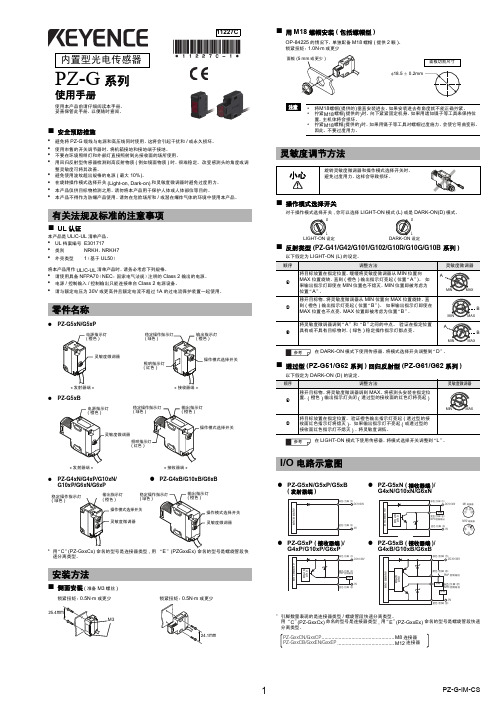
类型
透过型
反射型
ቤተ መጻሕፍቲ ባይዱ
回归反射型
标志检测
配置
缆线形状
输出 模式
普通
大功率
漫反射 长检测距离
漫反射 短检测距离
狭视野反射
限定反射
长检测距离
透明目标物检测
( 具有 P.R.O. 功能 ) ( 不具有 P.R.O 功能 )
红色
绿色
蓝色
缆线
NPN PZ-G51N PZ-G52N
PZ-G41N
PZ-G42N
电压
10 至 30VDC, 纹波 (P-P): 最大± 10%
额定值
消耗电流
发射器: 发射器: 最大 20 mA 最大 25mA
接收器: 接收器:
最大 28 mA 最大 28 mA
最大 34 mA
耐环境 抵性
防护等级 环境光度 环境温度 相对湿度
抗振性 抗冲击性
IEC,JEM: IP67 / NEMA: 4X,6,12 / DIN: IP69K 白炽灯 最大 5,000 (lx) ,日光:最大 20,000 (lx)
有关法规及标准的注意事项
■ UL 认证
本产品是 UL/C-UL 清单产品。
• UL 档案编号 E301717
• 类别
NRKH、NRKH7
• 外壳类型 1(基于 UL50)
将本产品用作 UL/C-UL 清单产品时,请务必考虑下列规格。
• 请使用具备 NFPA70(NEC:国家电气法规)注明的 Class 2 输出的电源。 • 电源 / 控制输入 / 控制输出只能连接单台 Class 2 电源设备。 • 请与额定电压为 30V 或更高并且额定电流不超过 1A 的过电流保护装置一起使用。
Oxymax COS61 产品简要使用说明说明书

Brief Operating InstructionsOxymax COS61Optical sensor for oxygen measurementThese instructions are Brief Operating Instructions.For detailed information, please read the Operating Instructions and the special instructions on the supplied CD-ROM.The complete device documentation comprises:•these Brief Operating Instructions•the Operating Instructions on the supplied CD-ROM•if necessary, certificates and calibration protocols (depending on version).KA00387C/07/EN/13.1271162650Documentation information Oxymax COS612Endress+Hauser1Documentation informationWarningsThe structure, signal words and safety colors of the signs comply with the specifications of ANSI Z535.6 ("Product safety information in product manuals, instructions and other collateral materials").Symbols usedSafety message structureMeaning!Cause (/consequences)Possible consequences if ignored ►Preventive measuresThis symbol alerts you to a dangerous situation.Failure to avoid the situation willresult in a fatal or serious injury.WARNING!Cause (/consequences)Possible consequences if ignored ►Preventive measuresThis symbol alerts you to a dangerous situation.Failure to avoid the situation can result in a fatal or serious injury.CAUTION!Cause (/consequences)Possible consequences if ignored ►Preventive measuresThis symbol alerts you to a dangerous situation.Failure to avoid this situation can result in minor or medium injury.Cause/situationPossible consequences if ignored ►Action/noteThis symbol alerts you to situations that can result in damage to property and equipment.È ä 1This symbol indicates a cross reference to a defined page (e.g. p. 1).È å 2This symbol indicates a cross reference to a defined figure (e.g. fig. 2).Additional information, tips Permitted or recommended Forbidden or not recommendedOxymax COS61Table of contents Table of contents1 Documentation information. . . . . . . . . . . . . . . . . . . . . . . . . . . . . . . . . . . . . . . . . . . . . . .22 Basic safety instructions. . . . . . . . . . . . . . . . . . . . . . . . . . . . . . . . . . . . . . . . . . . . . . . . . .4 2.1 Requirements for personnel . . . . . . . . . . . . . . . . . . . . . . . . . . . . . . . . . . . . . . . . . . . . . . . . . . . . . . . . . . . . . . . . . . . . . . . . 4 2.2 Designated use . . . . . . . . . . . . . . . . . . . . . . . . . . . . . . . . . . . . . . . . . . . . . . . . . . . . . . . . . . . . . . . . . . . . . . . . . . . . . . . . . . 4 2.3 Occupational safety . . . . . . . . . . . . . . . . . . . . . . . . . . . . . . . . . . . . . . . . . . . . . . . . . . . . . . . . . . . . . . . . . . . . . . . . . . . . . .4 2.4 Operational safety . . . . . . . . . . . . . . . . . . . . . . . . . . . . . . . . . . . . . . . . . . . . . . . . . . . . . . . . . . . . . . . . . . . . . . . . . . . . . . . 52.5 Product safety . . . . . . . . . . . . . . . . . . . . . . . . . . . . . . . . . . . . . . . . . . . . . . . . . . . . . . . . . . . . . . . . . . . . . . . . . . . . . . . . . . 53 Installation. . . . . . . . . . . . . . . . . . . . . . . . . . . . . . . . . . . . . . . . . . . . . . . . . . . . . . . . . . . .6 3.1 Installation conditions . . . . . . . . . . . . . . . . . . . . . . . . . . . . . . . . . . . . . . . . . . . . . . . . . . . . . . . . . . . . . . . . . . . . . . . . . . . . 6 3.2 Installation instructions . . . . . . . . . . . . . . . . . . . . . . . . . . . . . . . . . . . . . . . . . . . . . . . . . . . . . . . . . . . . . . . . . . . . . . . . . . . 63.3 Installation examples . . . . . . . . . . . . . . . . . . . . . . . . . . . . . . . . . . . . . . . . . . . . . . . . . . . . . . . . . . . . . . . . . . . . . . . . . . . . . 74 Wiring. . . . . . . . . . . . . . . . . . . . . . . . . . . . . . . . . . . . . . . . . . . . . . . . . . . . . . . . . . . . . .11 4.1 Direct connection to the transmitter . . . . . . . . . . . . . . . . . . . . . . . . . . . . . . . . . . . . . . . . . . . . . . . . . . . . . . . . . . . . . . . . . 11 4.2 Connection via junction box . . . . . . . . . . . . . . . . . . . . . . . . . . . . . . . . . . . . . . . . . . . . . . . . . . . . . . . . . . . . . . . . . . . . . . . 124.3 Post-connection check . . . . . . . . . . . . . . . . . . . . . . . . . . . . . . . . . . . . . . . . . . . . . . . . . . . . . . . . . . . . . . . . . . . . . . . . . . . 135 Commissioning . . . . . . . . . . . . . . . . . . . . . . . . . . . . . . . . . . . . . . . . . . . . . . . . . . . . . . .14 5.1 Function check . . . . . . . . . . . . . . . . . . . . . . . . . . . . . . . . . . . . . . . . . . . . . . . . . . . . . . . . . . . . . . . . . . . . . . . . . . . . . . . . 14 5.2 Calibration . . . . . . . . . . . . . . . . . . . . . . . . . . . . . . . . . . . . . . . . . . . . . . . . . . . . . . . . . . . . . . . . . . . . . . . . . . . . . . . . . . . . 14 Endress+Hauser3Basic safety instructions Oxymax COS614Endress+Hauser2Basic safety instructions2.1Requirements for personnel►Installation, commissioning, operation and maintenance of the measuring system must only be carried out by trained technical personnel.►The technical personnel must be authorized by the plant operator to carry out the specified activities.►The electrical connection may only be performed by an electrical technician.►The technical personnel must have read and understood these Operating Instructions and must follow the instructions they contain.►Measuring point faults may only be rectified by authorized and specially trained personnel.Repairs not described in the enclosed Operating Instructions may only be carried out directly at the manufacturer's or by the service organization.2.2Designated useThe oxygen sensor is suitable for continuous measurement of dissolved oxygen in water.Typical applications are:•Measuring, monitoring and regulating the oxygen content in activated sludge basins.•Monitoring the oxygen content in the sewage treatment plant outlet.•Monitoring, measuring and regulating the oxygen content in public waters and fish farming water.•Monitoring of oxygen enrichment in drinking water.Any other use than the one described here compromises the safety of persons and the entire measuring system and is not permitted.The manufacturer is not liable for damage caused by improper or non-designated e in not specified applicationsMeasurement errors and failures up to the breakdown of the measurement point possible ►Only use the product acc. to its specification.►Observe the technical data of the nameplate.2.3Occupational safetyAs the user, you are responsible for complying with the following safety conditions: •Installation instructions•Local prevailing standards and regulations.Electromagnetic compatibilityWith regard to electromagnetic compatibility, this device has been tested in accordance with the applicable European standards for industrial applications.The electromagnetic compatibility indicated only applies to a device that has been connected inaccordance with the instructions in these Operating Instructions.Oxymax COS61Basic safety instructionsEndress+Hauser 52.4Operational safety►Before commissioning the entire measuring point, make sure all the connections are correct. Ensure that electrical cables and hose connections are not damaged.►Do not operate damaged products, and safeguard them to ensure that they are not operated inadvertently. Mark the damaged product as defective.►If faults cannot be rectified, the products must be taken out of service and secured against unintentional commissioning.CAUTION!The cleaning system is not switched off during calibration or maintenance activities Risk of injury due to medium or cleaning agent►If a cleaning system is connected, switch it off before removing a sensor from the medium.►If you are not switching off the cleaning system because you wish to test the cleaning function, wearprotective clothing, goggles and gloves or take other appropriate measures.2.5Product safetyThe product is designed to meet state-of-the-art safety requirements, has been tested and left the factory in a condition in which it is safe to operate. Relevant regulations and European standards have been observed.Installation Oxymax COS616Endress+Hauser3Installation3.1Installation conditions3.1.1OrientationOther angles and overhead installation are not recommended. Reason: possible sediment formation and resulting falsification of measured value.3.1.2Mounting location•Select the installation location so that there is easy access for later calibration.•Make sure that upright posts and assemblies are secured safely and vibration-free.•Select an installation location which produces a typical oxygen concentration.3.2Installation instructions3.2.1Installing a measuring pointFor immersed operation, install the individual modules away from the basin on a solid base. Only carry out the final installation at the intended installation location.For a complete installation of a measuring point, proceed as follows:1.Install a retractable or a flow assembly (if used) into the process.2.Connect the water supply to the rinse connections (if you use an assembly with cleaning function).3.Install and connect the oxygen sensor.4.Install an immersion or an suspension assembly (if used) into the process.Fig.1: Angle of installation ARecommended angle of installation: 0 (180)˚Oxymax COS61InstallationEndress+Hauser 7No assembly used, sensor not correctly installed, grounding regulations not observed Risk of damaging the sensor cable, no protection to electromagnetic interferencies ►Screw the sensor into the assembly so that the cable is not twisted.►Avoid exerting excessive tensile force on the cable (e.g. from jerky pulling).►When using metallic assemblies and installation equipment, comply with national groundingregulations.►Observe the sensor installation instructions of the Operating Instructions of the assembly used.3.3Installation examples3.3.1Immersion operationUniversal assembly holder and chain assemblyFig.2: Chain holder, rail mounted 1Chain2Flexdip CYH112 holder 3Rail4Oxymax sensor5Flexdip CYA112 wastewater assemblyFig.3: Chain holder, mounted to a post 1Weather protection cover 2Controller / transmitter 3Chain4Flexdip CYA112 wastewater assembly 5Oxymax sensor6Flexdip CYH112 holderInstallation Oxymax COS61 Universal assembly holder and fixed immersion assemblyFig.4: Assembly holder with immersion tube1Weather protection cover2Controller / transmitter3Immersion assembly Flexdip CYA1124Oxymax sensor5Assembly holder Flexdip CYH1128Endress+HauserOxymax COS61InstallationEndress+Hauser 9Basin rim mounting with immersion tubeFloating bodyFig.5: Basin rim mounting 1Pentulum holder CYH1122Assembly Flexdip CYA1123Float of assembly CYA1124Oxymax sensorFig.6: Floating body1234567Cable route with strain relief and rain protectionMounting ring for ropes and chains with locking screw Lugs Ø15, 3 x 120 ˚ for anchoring Saltwater-resistant plastic floatPipe 40x1, stainless steel 1.4571 (AISI 316Ti)Shock absorber and weight Oxygen sensorInstallation Oxymax COS6110Endress+Hauser3.3.2Flow assembly3.3.3Retractable assemblyFig.9: Permissible and impermissible sensor installation positions with retractable assembly COA4511Ascending pipe, best position2Horizontal pipe, sensor top down, impermissible due to air cushion or foam bubble forming 3Horizontal pipe, installation with permissible installation angle (acc. to sensor version)4Overhead installation, critical due to possible sediment buildup on fluorescence cap 5Down pipe, impermissibleFig.7: Flow assembly COA250-B 1Screw-in part for sensor 2Screw ring 3Meter body4Connection thread G¾5Dummy plug (connection for spray head COR3)Fig.8: Bypass installation1Main line 2Medium return 3Oxygen sensor4, 7Manually actuated or solenoid valves 5Flow assembly COA250-B 690 ˚ pipe bracket 8Medium removalOxymax COS61WiringEndress+Hauser 114WiringWARNING!Device is energizedImproper connection can cause injury or death.►The electrical connection must only be carried out by a certified electrician.►Technical personnel must have read and understood the instructions in this manual and mustadhere to them.►Prior to beginning any wiring work, make sure voltage is not applied to any of the cables.4.1Direct connection to the transmitter4.1.1Field installationConnect the sensor directly to the transmitter by using the special measuring cable with SXP plug.4.1.2Panel mounting•Remove the SXP connector (transmitter side!) from the cable.•Refer to the following table for the cable assignment and the assigned terminals for Liquisys COM223-WX/WS.•Please note that the cable assignment varies depending on the sensor version (fixed cable or TOP68 connection).Fig.10: SXP plugTerminal COM223Sensor with fixed cable (OMK)Sensor with TOP68 connection (CYK71)Core Assignment Core Assignment 87YE +U B YE +U B 0GY 0VWH 0V96PK Com. (digital)GN Communication (digital)97BU Com. (digital)BN Communication (digital)88BN–U BKoax innen–U BWiring Oxymax COS6112Endress+Hauser4.2Connection via junction boxTo lengthen the sensor connection beyond the length of the fixed cable, you require a junction box VS.Fig.11: Junction box VS to a field device 1SXP plug to field device 2SXP plug from sensorFig.12: Junction box VS to a panel mounted device 2SXP plug from sensor3Measuring cable (OMK) to the transmitter 4Connection department of the transmitterOxymax COS61WiringEndress+Hauser 134.3Post-connection checkInstrument status and specificationsRemarks Are the sensor, assembly, junction box or cable damaged?Visual inspection Electrical connectionRemarksAre the installed cables strain-relieved and not twisted ?Long enough length of cable core stripped and correct in terminal?Check seating (pull slightly)Are all the screws terminals properly tightened ?TightenAre all the cable entries installed, tightened and sealed ?For cable entries lateral: cable loops downwards for water to be able to drip off.Are all the cable entries installed downwards or lateral ?Commissioning Oxymax COS6114Endress+Hauser5Commissioning5.1Function checkBefore first commissioning, check if:•the sensor is correctly installed •the electrical connection is correct.If using an assembly with automatic cleaning, check the correct connection of the cleaning agent (e.g. water or air).WARNING!Escaping process mediumRisk of injury from high pressure, high temperatures or chemical hazards►Before applying compressed air to an assembly with cleaning facility, make sure the connections arecorrectly fitted.►Do not install the assembly in the process if you cannot make the correct connection reliably.5.2CalibrationThe sensor is calibrated at the factory. A new calibration is only needed in special situations.1.Remove the sensor from the medium.2.Clean the outside of the sensor with a damp cloth.3.Then wait while the sensor adjusts to the temperature of the ambient air. This takes about 20minutes. Check that the sensor is not in direct sunlight during this time.4.If the measured value display on the transmitter is stable, carry out the calibration in accordance with the Operating Instructions of the transmitter.5.Place the sensor in the medium again.Make sure you comply with the instructions for calibration in the Operating Instructions of thetransmitter.Oxymax COS61Commissioning Endress+Hauser15KA00387C/07/EN/13.12 FM9。
一体式钢筋扫描仪最佳操作指南打印版

HC-GY61一体式钢筋扫描仪最佳操作指南参加培训单位:仪器能够正常开、关机、保证操作前仪器电量充足。
选择“开始检测”菜单进入,选择“仪器标定”,版本号如是2.26c 为最新版本,如不是请与厂家联系。
完成后按任意键退出。
1.准备工作 :保证当前电量充足最新仪器版本2.开机设置 :开机后,选择“参数设置 ”菜单进入,量程选择“小”,主筋间距选择“—”后返回。
1选择“开始检测”菜单进入,在“厚度检测”界面,将钢筋直径输入为“16”,箍筋间距选择“>125”后返回。
2测试精度简易验证 : 用单根Φ16的钢筋,配上聚苯板进行测量;如测试误差< 2mm ,证明仪器正常。
否则应及时联系生产厂家。
测量误差误差< 2mm3.1常规检测 :首先选择“厚度检测”界面进行数量判断。
确保仪器平行放置在试块最左边;然后匀速向右推动;厚度检测保持匀速向右推动常规检测 :如仪器顺利显示出5根钢筋和对应的保护层厚度与间距;说明此试块内钢筋分布的环境我们的仪器可以轻松应对;按“Fn”键清屏后再次测量即可对每根钢筋位置进行标记,并用直尺对钢筋间距进行测量;直接读取仪器显示的保护层厚度值;可重复几次复核,最后提交答案。
3.1密集钢筋检测 : 如“厚度检测”重复2次测量都不能确定是5根钢筋(可能是4根或6根),说明此试块内有2根钢筋间距密集的布置;应选择“波形扫描”界面进行扫描,波形扫描时仪器一定要匀速向右推进;通过波形图能够明显看出密集钢筋分布情况,并确定2根密集筋的位置;然后返回“厚度检测”界面对其它3根间距较大的钢筋地方进行钢筋位置标记,同时读取保护层厚度。
3.2波形扫描密集钢筋2根钢筋水平分布密集钢筋直接“厚度检测 ”模式保护层厚度会有2mm 误差。
以下方法能修正误差,检测出准确的钢筋间距和保护层厚度。
首先用“厚度检测”界面进行测量,仪器从左向右扫描,短距离内会连续出现三根钢筋,定位出第一根钢筋后做好标记,后面两根钢筋位置不做参考;然后操作人员站到试块对面还是从左往右扫描,同样定位出第一根钢筋位置;第一根钢筋后做好标记然后操作人员站到试块对面此时标记的两个点就是两根钢筋的准确位置。
CP Microwave Oven 60hz Compact Models 技术手册说明书

ServiceCommercial Microwave Oven60hz Compact Modelsstarting at Serial No. 1910000000 Service ManualThis Base Manual covers all Commercial Microwave Ovens. Refer to individual Technical Sheet for information on a specific model.This manual is to be used by qualifiedservice technicians only. ACP, Inc.does not assume any responsibility forproperty damage or personal injury forimproper service procedures done byan unqualified person.164000441TABLE OF CONTENTSImportant Safety Instructions ............................................................................................. 3-4 Oven Specifications .......................................................................................................... 5-6 Quick Start Reference Guide ............................................................................................. 7-8 Component Location ........................................................................................................ 9-13 Airflow .. (14)Component Testing ....................................................................................................... 15-17 Service Mode. (17)Power Output Test (18)Wiring and Schematic Diagrams.................................................................................... 19-222IMPORTANT SAFETY INSTRUCTIONSImportant Safety Information. Read before using this oven.Keep these instructions for future reference.If the oven changes ownership, be sure this guide accompanies oven. For additional product documentation or more detailed operating instructions visit:CONTACT INFORMATIONAny questions or to locate an authorized ACP servicer, call ACP ComServ Service Support.–Inside the U.S.A. or Canada, call toll-free 866-426-2621.–Outside the U.S.A. and Canada, call 319-368-8120.–Email: **********************************.Warranty service must be performed by an authorized ACP servicer. ACP also recommends contacting an authorized ACP servicer, or ACP ComServ Service Support if service is required after warranty expires.PRECAUTIONS TO AVOID POSSIBLE EXPOSURE TO EXCESSIVE MICROW A VE ENERGYA. DO NOT attempt to operate this oven with the door open since open door operation can resultin harmful exposure to microwave energy.It is important not to defeat or tamper with the safety interlocks.B. DO NOT place any object between the oven front face and the door or allow soil or cleanerresidue to accumulate on sealing surfaces.C. DO NOT operate the oven if it is damaged. It is particularly important that the oven door closeproperly and that there is no damage to the:1. door (bent)2. hinges and latches (broken or loosened)3. door seals and sealing surfaces.D. The oven should not be adjusted or repaired by anyone except properly qualified servicepersonnel.3To avoid risk of personal injury or property damage, observe the following safety CAUTIONinstructions:General Use:1. Do not use regular cooking thermometers in oven. Most cooking thermometers contain mercury and maycause an electrical arc, malfunction, or damage to oven.2. Never use paper, plastic, or other combustible materials that are not intended for cooking.3. When cooking with paper, plastic, or other combustible materials, follow manufacturer’s recommendationson product use.4. Do not use paper towels which contain nylon or other synthetic fibers. Heated synthetics could melt andcause paper to ignite.5. To avoid surface deterioration, keep the oven in a clean condition. Infrequent cleaning could adverselyaffect the life of the appliance and possible result in a hazardous situation.6. Clean oven regularly and remove any food deposits.Heating Foods and Liquids:7. Liquids such as water, coffee, or tea are able to be overheated beyond the boiling point without appearing tobe boiling due to surface tension of the liquid. Visible bubbling or boiling when the container is removed from the microwave oven is not always present. THIS COULD RESULT IN VERY HOT LIQUIDSSUDDENLY BOILING OVER WHEN A SPOON OR OTHER UTENSIL IS INSERTED INTO THE LIQUID.To reduce the risk of injury to persons:•Do not overheat the liquid.•Stir the liquid both before and halfway through heating it.•Do not use straight-sided containers with narrow necks.•After heating, allow the container to stand in the microwave for a short time before removing it.b. Use extreme care when inserting a spoon or other utensil into the container.8. Do not deep fat fry in oven. Fat could overheat and be hazardous to handle.9. Do not cook or reheat eggs in shell or with an unbroken yolk using microwave energy.Pressure may buildup and erupt. Pierce yolk with fork or knife before cooking.10. Pierce skin of potatoes, tomatoes, and similar foods before cooking with microwave energy.When skin ispierced, steam escapes evenly.11. Do not heat sealed containers or plastic bags in oven. Food or liquid could expand quickly and causecontainer or bag to break. Pierce or open container or bag before heating12. Do not heat baby bottles in oven.13. Baby food jars shall be open when heated and contents stirred or shaken before consumption, in orderto avoid burns.14. Never use oven to heat alcohol or food containing alcohol as it can more easily catch fire ifoverheated.Additional Microwave Oven Safety Instructions:15. Do not operate equipment without load or food in oven cavity.16. Use only popcorn in packages designed and labeled for microwave use. Popping time variesdepending on oven wattage. Do not continue to heat after popping has stopped. Popcorn will scorch or burn. Do not leave oven unattended.17. Do not use metal utensils in oven.18. An authorized servicer MUST inspect equipment annually. Record all inspections and repairs for futureuse.45InstallationUnpacking Oven∙Inspect oven for damage such as dents in door or dents inside oven cavity.∙Report any dents or breakage to source of purchase immediately. Do not attempt to use oven if damaged.∙Remove all materials from oven interior.∙If oven has been stored in extremely cold area, wait a few hours before connecting power.Radio InterferenceMicrowave operation may cause interference to radio, television, or similar. Reduce or eliminate interference by doing the following: Clean door and sealing surfaces of oven according to instructions in “Care and Cleaning” section.Place radio, television, wireless routers, etc. as far away as possible from oven.Use a properly installed antenna on radio, television, etc. to obtain a stronger signal reception.6QUICK START GUIDERefer to Owner’s Manual for Safety Statements. Complete Owner’s Manual available online.(C)(i) (ii) ( iii) (iv) (v) (vi)OVEN CLEARANCESA. Allow at least 2” (5.1 cm) of clearancearound top of oven. Proper airflow around oven cools electricalcomponents. With restricted air flow,oven may not operate properly and lifeof electrical parts is reduced.B. General market models: There is notan installation clearance requirementfor the back of the oven.HDC21RB2, MCHDC21, HDC21DQonly: Allow at least 1” (2.54 cm) ofclearance around back of oven.C. Allow at least 1” (2.54 cm) of clearance CONTROL PANEL FEATURES(A) USB Port(B) Display(C) Number Keypads(D) Start/ OK Keypad(E) Stop/ Reset Keypad(F) Secondary Function KeypadsTo activate, press and hold correspondingnumber keypad.(i) Manual Time Entry Mode (keypad “1”)(ii) Power Level (keypad “2”)(iii) Programming Mode (keypad “3”)(iv) User Options (number keypad “4”)(v) X2 - Double Quantity Cooking (keypad “5”)(vi) Menu A/B (keypad “6”)around sides of oven.D. Install oven so oven bottom is at least3 feet (91.5 cm) above floor. Preset Program Keypads To cook food using preprogrammed cookingsequences:1. Open oven door, place food in oven,and close oven door.2. Press desired number keypad(s).3. Oven operates and time counts down.4. At the end of the cooking cycle, theoven beeps. Carefully remove foodfrom oven.X2 - DOUBLE QUANTITY COOKING 1. Press and hold number keypad “5”/ X2to toggle double quantity feature ON.“X2” appears at top center of screenwhen enabled.2. Press desired number keypad(s).Display counts down cooking time fortwo quantities.MENU A/B (select models)Press and hold number keypad “6” to toggle between A and B menus. So…how do I use it?Manual Time Entry ModeTime entry mode allows the user to manually enter cook time and power level, without changing the preset program keypads.1. Open oven door, place food in oven, and close door.2. Press and hold number keypad “1”/ TIME ENTRY.3. Press number keypads to enter desired cook time.4. Press and hold number keypad “2”/ POWER LEVEL to change power level.•Press number keypads to ente r % microwave power (“1”=10%, “2”=20%,etc.) For 100% power level, press and hold number keypad “2”/ POWER LEVEL.5. Press START/OK keypad to begin cooking.6. At the end of the cooking cycle, the oven beeps. Carefully remove food from oven.Programming Mode1. Pre ss and hold number keypad “3”/ PROGRAM.2. Press number keypad(s) to open the desired program location.3. To edit name: Press number keypad “0”. Press number keypads to enter recipe name.Press START/OK keypad.4. To edit cook time for Stage One: Press number keyp ad “1”. Press number keypads toenter cook time. Press START/OK keypad.5. To edit power level for Stage One: Press number keypad “5”. Press number keypads toenter % microwave power (“1”=10%, “2”=20%,etc.). For 100% power level, press and hold number keypad “2”/ POWER LEVEL.6. If stage cooking is desired, repeat steps 4-5 for each additional stage, substitutingcorresponding number keypads for each stage.7. To save and exit programming mode: Press START/OK keypad.(A) (B) (F) (D) (E)This document covers HDC*, MDC*, DEC*, MCHDC*, and CRC* modelsAC BD7Access and Modify User OptionsThere are several options you can change to customize the operation of theoven for your business. Options are shown below. The factory setting isshown in bold type.1. Press and hold keypad number “4”/ USER OPTIONS.If prompted, enter the PIN Code and press START/OK keypad2. Press the START/OK keypad to scroll through pages of user options3. To access an individual user option, press the corresponding number keypad•To change the setting, press corresponding number keypad•To return to User Options Menu, press START or STOP/RESET4. Press STOP/RESET keypad to exit User Options MenuSTANDARD DEFAULT PER MODEL (FACTORY SETTINGS IN BOLD)Factory setting may vary by model* Available on select models only (only displayed in User Options menu if factory option is enabled)OVEN CONSTRUCTIONBLOWER, CAPACITOR, DIODE, INTERLOCKDOORCONTROL BOARD, MAGNETRONS, DUCTS, FUSETRAY, CAVITY, ANTENNASWRAPPER, ACCESS PANEL, LAMPAIR FLOW1.AIR ENTERS THROUGH FRONT FILTER2. AIR IS DRAWN INTO BLOWER3. AIR PUSHED THROUGH MAGNETRONS4. AIR PUSHED CAVITY AND EXITS THROUG CAVITY DUCTSCOMPONENT TESTINGretest.Blower Motor Remove all wires from motor.Measure resistance COM to 208Measure resistance COM to 230Measure resistance 208 to 230Approx 23ΩApprox 26ΩApprox 3ΩStirrer Motor- 25RPM Remove all wires from motor.Measure coil resistance Approximately 25k Ω.COM TransformerDischarge CapacitorRemove all wires from terminals, andmeasure resistance from:230 to Common………………………208 to Common………………………Terminal 5 to 6………………………..Terminal 7 to 8………………………Terminal 4 to Ground ………………….<1 Ω.<1 Ω.<1 Ω.<1Ω27Ω ±10%Interlock SwitchAssemblyDisconnect wires to switch.With door open measure resistancefrom:Primary – Terminals………….Monitor – Terminals………….Secondary – Terminals………With door closed measureresistance from:Primary –Terminals………….Monitor –Terminals………….Secondary – Terminals………Open/Infinite ΩClosed/ContinuityOpen/Infinite ΩClosed/ContinuityOpen/Infinite ΩClosed/ContinuityTouch Panel Assembly Disconnected from Main Board Pad Traces1 1 to 8 to 10 0-150Ω2 1 to 7 to 10 0-150Ω3 1 to 6 to 10 0-150Ω4 1 to5 to 10 0-150Ω5 1 to 4 to 10 0-150Ω6 1 to 3 to 10 0-150Ω7 1 to 8 to 9 0-150Ω8 1 to 7 to 9 0-150Ω9 1 to 6 to 9 0-150Ω0 1 to 5 to 9 0-150ΩStart 1 to 4 to 9 0-150ΩStop 1 to 4 to 8 0-150ΩSERVICE MODETO ACCESS THE SERVICE MODE:∙PRESS AND HOLD THE “7” PAD UNTIL THE PIN PROMPT IS DISPLAYED∙AT THE PIN PROMPT, ENTER 1,3,5,7 then 9 THEN SELECT FROM THE FOLLOWING:o 1 – USAGEThis shows Door Cycles, Tube Cycles, and Tube Hours.o 2 - ERROR HISTORYThis shows any Error Codes that have occurredo 3 - PIN CODEThis reveals the 4 digit PIN code required for programming (if enabled) o 4 - VOLTAGE SWITCHING (not available on 120vac units)Allows selection of Forced 208, Sensing (Auto Sense), or Forced 230 o 5 - EXPORT TO USBThis option requires a USB be inserted. Files that contain USAGE,OPTIONS & ENGINEERING SETTINGS, MENU PROGRAMMING, andERROR CODES will be downloaded.NOTE: Pressing the grey “stop” pad will navigate backwards.POWER OUTPUT TESTAll Amana and Menumaster microwave oven power outputs are rated using the IEC705standards. Using the IEC705 test method requires precision measurements and equipment that is not practical to be performed in the field. Using the test shown below will indicate if the oven performance is satisfactory.Test equipment required:∙1000 ml test container and thermometer (Amana power test kit Fahrenheit / Menumaster power test kit Celsius).∙Digital watch / watch with a second hand for use on ovens with electromechanical timers.Important Notes:∙Low line voltage will cause low temperature rise / power output.∙Ovens must be on a dedicated circuit, properly grounded, and polarized. Other equipment on the same circuit may cause a low temperature rise / power output.∙This test and results are not a true IEC705 test procedure and are only intended to provide servicers with an easy means of determining if the microwave oven cooking output is correct.Procedure1. Fill the test container to the 1000 ml line with cool tap water.NOTE:Water temperature should be approximately 60° F / 16° C.2. Using the thermometer, stir water for five to ten seconds; measure, and record the temperature (T1).3. Place test container of water in the center of oven cavity and close door.4. Heat the water for a 33-second full power cycle.NOTE:Use a digital watch or a watch with a second hand for ovens with electromechanical timers.1. At end of the cycle, remove test container. Using the thermometer, stir water for five to ten secondsand record temperature (T2).2. Subtract the starting water temperature (T1), from the ending water temperature (T2) to obtain thetemperature rise (∆T).3. If the temperature rise (∆T) meets or exceeds the minimum, the test is complete. If the temperaturerise (∆T) fails to meet the minimum temperature rise, test the line voltage to verify it is correct. Thenrepeat steps 1-6 making sure to change the water. If the temperature rise (∆T) fails to meet theminimum temperature rise again the oven will require service.OMPONENT TESTINGWIRING AND SCHEMATIC DIAGRAMSHDC12A2 P2007001MMDC12A2 P2007002MHDC182 P2007004M MDC182 P2007006M HDC1815 P2007003M HDC18SD2 P2007005M HDC212 P2007011M MDC212 P2007014M MDC182CA P2007008M MDC182CD P2007009M CRC18T2OG2 P2007010M HDC21RB2 P2007012M HDC21DQ P2007013M MCHDC21 P2007015M CRC21T2RLPF P2007016MMDC182SA P2007025M MDC212SA P2007031MMDC182K P2007007M。
旋坤 LoRa 阀控水表无线模块 XKER611 使用说明书
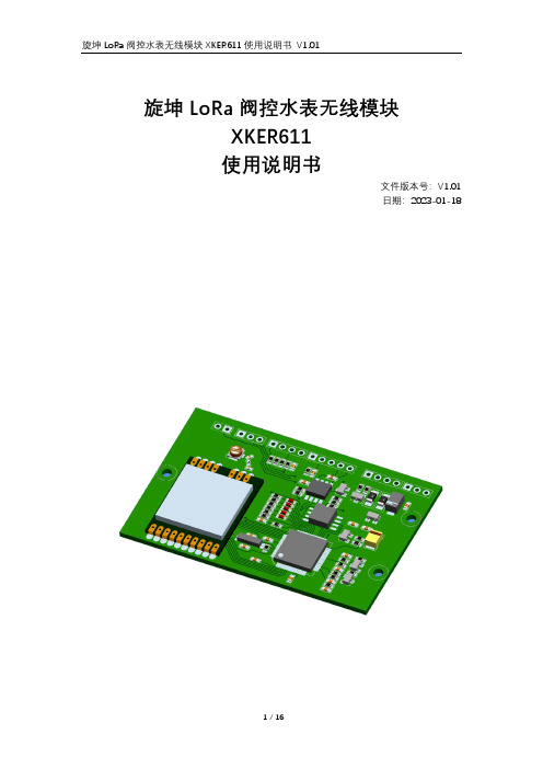
旋坤LoRa阀控水表无线模块XKER611使用说明书文件版本号:V1.01日期:2023-01-18目录1. 产品概述 (4)1.1. 产品简介 (4)1.2. 产品参数 (4)1.3. 产品清单 (4)2. 产品结构及尺寸 (5)2.1. 产品接口说明 (5)2.2. 指示灯说明 (6)2.3. 产品外形尺寸 (7)3. 快速使用 (8)3.1. 步骤1 (8)3.2. 步骤2 (8)3.3. 步骤3 (9)4. 产品功能和特点 (9)4.1. 水量计量 (9)4.2. 防强磁干扰 (9)4.3. 单边计量报警 (10)4.4. 电池低压报警 (10)4.5. 电池掉电报警 (10)4.6. 掉电保护 (10)4.7. 低功耗 (10)4.8. 唤醒功能 (10)4.9. 固件更新 (11)4.10. 无线中继 (11)4.11. 无线写号 (11)4.12. 防水功能 (11)5. 操作说明 (11)5.1. 二次加工操作说明 (11)5.2. 产品测试和设置操作说明 (14)6. 安全注意事项 (15)6.1. 接入电源时VCC和GND不能反插 (15)7. 产品常见问题 (16)7.1. 抄不了表号 (16)7.2. 水表发生异常告警时,LED4不会亮 (16)8. 制造商信息 (16)1.产品概述1.1.产品简介LoRa阀控水表无线模块,是LoRa无线远传水表的核心部件,主要负责水量计量、接收处理抄表命令、接收和处理开关阀命令,以及异常报警上报等功能。
LoRa阀控水表无线模块,根据水表模具和客户要求,其外型、尺寸和硬件接口可能有所不同,但产品的核心功能是一样的。
1.2.产品参数1.3.产品清单2.产品结构及尺寸2.1.产品接口说明图2 接口对照表:2.2.指示灯说明2.3.产品外形尺寸图33.快速使用3.1.步骤1根据实际需要,在模块PCB对应位置焊接所需的排插。
图43.2.步骤2将电池与模块连接。
太阳能路灯说明书
太阳能路灯说明书TYN-012目录产品说明产品介绍⋯⋯⋯⋯⋯⋯⋯⋯⋯⋯⋯⋯⋯⋯⋯⋯⋯⋯⋯⋯⋯⋯⋯⋯⋯⋯⋯⋯3工作原理⋯⋯⋯⋯⋯⋯⋯⋯⋯⋯⋯⋯⋯⋯⋯⋯⋯⋯⋯⋯⋯⋯⋯⋯⋯⋯⋯⋯3产品质保⋯⋯⋯⋯⋯⋯⋯⋯⋯⋯⋯⋯⋯⋯⋯⋯⋯⋯⋯⋯⋯⋯⋯⋯⋯⋯⋯⋯3免责条款⋯⋯⋯⋯⋯⋯⋯⋯⋯⋯⋯⋯⋯⋯⋯⋯⋯⋯⋯⋯⋯⋯⋯⋯⋯⋯⋯⋯3产品构造主要部件⋯⋯⋯⋯⋯⋯⋯⋯⋯⋯⋯⋯⋯⋯⋯⋯⋯⋯⋯⋯⋯⋯⋯⋯⋯⋯⋯⋯4产品清单⋯⋯⋯⋯⋯⋯⋯⋯⋯⋯⋯⋯⋯⋯⋯⋯⋯⋯⋯⋯⋯⋯⋯⋯⋯⋯⋯⋯6储存及工作环境⋯⋯⋯⋯⋯⋯⋯⋯⋯⋯⋯⋯⋯⋯⋯⋯⋯⋯⋯⋯⋯⋯⋯⋯⋯7主要部件简介⋯⋯⋯⋯⋯⋯⋯⋯⋯⋯⋯⋯⋯⋯⋯⋯⋯⋯⋯⋯⋯⋯⋯⋯7安装说明安装前须知事项⋯⋯⋯⋯⋯⋯⋯⋯⋯⋯⋯⋯⋯⋯⋯⋯⋯⋯⋯⋯⋯⋯⋯⋯⋯8安装前准备⋯⋯⋯⋯⋯⋯⋯⋯⋯⋯⋯⋯⋯⋯⋯⋯⋯⋯⋯⋯⋯⋯⋯⋯⋯⋯⋯9安装操作流程⋯⋯⋯⋯⋯⋯⋯⋯⋯⋯⋯⋯⋯⋯⋯⋯⋯⋯⋯⋯⋯⋯⋯⋯⋯11安装注意⋯⋯⋯⋯⋯⋯⋯⋯⋯⋯⋯⋯⋯⋯⋯⋯⋯⋯⋯⋯⋯⋯⋯⋯⋯⋯⋯12注意项目⋯⋯⋯⋯⋯⋯⋯⋯⋯⋯⋯⋯⋯⋯⋯⋯⋯⋯⋯⋯⋯⋯⋯⋯⋯⋯⋯12安装顺序⋯⋯⋯⋯⋯⋯⋯⋯⋯⋯⋯⋯⋯⋯⋯⋯⋯⋯⋯⋯⋯⋯⋯⋯⋯⋯⋯12安装手册选址⋯⋯⋯⋯⋯⋯⋯⋯⋯⋯⋯⋯⋯⋯⋯⋯⋯⋯⋯⋯⋯⋯⋯⋯⋯⋯⋯⋯⋯12地基⋯⋯⋯⋯⋯⋯⋯⋯⋯⋯⋯⋯⋯⋯⋯⋯⋯⋯⋯⋯⋯⋯⋯⋯⋯⋯⋯⋯⋯12 路灯安装太阳能板的安装⋯⋯⋯⋯⋯⋯⋯⋯⋯⋯⋯⋯⋯⋯⋯⋯⋯⋯⋯⋯⋯⋯⋯13LED 灯的安装⋯⋯⋯⋯⋯⋯⋯⋯⋯⋯⋯⋯⋯⋯⋯⋯⋯⋯⋯⋯⋯⋯⋯⋯⋯13控制器的安装⋯⋯⋯⋯⋯⋯⋯⋯⋯⋯⋯⋯⋯⋯⋯⋯⋯⋯⋯⋯⋯⋯⋯⋯⋯13蓄电池的安装⋯⋯⋯⋯⋯⋯⋯⋯⋯⋯⋯⋯⋯⋯⋯⋯⋯⋯⋯⋯⋯⋯⋯⋯⋯13各部件接线⋯⋯⋯⋯⋯⋯⋯⋯⋯⋯⋯⋯⋯⋯⋯⋯⋯⋯⋯⋯⋯⋯⋯⋯⋯⋯14路灯吊装⋯⋯⋯⋯⋯⋯⋯⋯⋯⋯⋯⋯⋯⋯⋯⋯⋯⋯⋯⋯⋯⋯⋯⋯⋯⋯⋯14注意事项⋯⋯⋯⋯⋯⋯⋯⋯⋯⋯⋯⋯⋯⋯⋯⋯⋯⋯⋯⋯⋯⋯⋯⋯⋯⋯⋯14 故障处理⋯⋯⋯⋯⋯⋯⋯⋯⋯⋯⋯⋯⋯⋯⋯⋯⋯⋯⋯⋯⋯⋯⋯⋯15 太阳能路灯介绍产品介绍LED 太阳能路灯是以太阳能作为电能供给用来提供夜间道路照明,采用高光效LED 光源设计,具有亮度高、绿色环保、安装简便、工作稳定可靠、不敷设电缆、不消耗常规能源,使用寿命长等优点,特别是本品控制器采用多重节能线路设计,拥有过充、过放、反接,自动光控装置,全面提升LED发光效率,极大节约电能。
钢筋扫描仪-HC-GY61
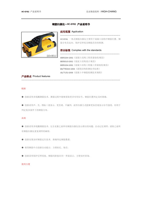
钢筋扫描仪—HC-GY61 产品说明书应用范围ApplicationHC-GY61一体式钢筋扫描仪主要用于混凝土结构中钢筋位置、钢筋分布及走向、保护层厚度及钢筋直径的探测。
符合标准Complies with the standards------------------------------------------------------------------------------------------GB50204-2002《混凝土结构工程质量验收规范》GB50010-2002《混泥土结构设计规范》GB50204-2002《混凝土结构工程施工质量验收规范》GB/T50344-2004《建筑结构检测技术标准》JGJ/T152-2008《混凝土中钢筋检测技术规程》产品特点Product features------------------------------------------------------------------------------------------------------------------------------------------------------精准●创新采用多线圈测量技术,测量过程中能够获取更多有用信号,钢筋位置判定及时准确。
●创新采用声、光、图标三重显示,更直观、不漏判。
波形扫描方式能够更加直观显示信号强度,有利于判定复杂条件下的钢筋分布。
高效●创新采用多线圈测量技术,完全克服之前所有钢筋扫描仪显示滞后的问题。
自动记忆调零,消除之前所有钢筋扫描仪重复调零的麻烦。
●创新实现实时钢筋定位技术,准确判定钢筋数量。
●相邻钢筋中点创新自动提示,方便钻孔、取芯。
●创新采用保护层厚度值、钢筋间距值在同一界面显示,方便实时查询。
使用方便●一体式紧凑结构设计,抛弃之前所有钢筋扫描仪显示器与感应器通过连接线连接带来缠绕等一切不方便的烦恼。
操作界面Operation interface技术参数Technical Parameters------------------------------------------------------------------------------------------------------------------------------------------------------。
威安特科技带遥控太阳能红外报警器中文说明书(新)

X
不要直接面对 冷 气/暖 气
X
安装在稳固的地方
Detector
X
这样安装不能充电
X
远离强干扰
X
远离高压
ROAD HUGGER
X
移动的汽车可 能导致误报
关于安装角度
探测器对入侵角度存在机理上的差异。
最不敏感
最敏感
对于这些方向运 动的人体,可能 探测距离会缩短
关于安装位置
不合理的安装位置
最佳安装位置
窗
-自 动数字温度补偿 -抗 强 白 光 和 太 阳 光 - 18段的菲涅尔透镜 -全 密 封 式 的 光 学 零 件 -水平调整:180° 垂直调整:30° -自 动 数 字 脉 冲 信 号 处 理
安装指南
安装总则
虽然探测器的性能很强大,但是,在安装过程中,尽量避免以下的不良安装方式, 可以使得探测器获得更佳、更稳定的探测使用性能!
工 作 ,并 保 证 探 测 器 有 一 个 宽 阔 视 野 。先
把塑胶塞子打进安装墙上(或其他安装
位置)用三颗螺丝把产品固定好。
卸下前盖,逆 时针松开底部螺丝,打开盖
子后拨动电源开关即可使产品工作。然
1
后,按图示方式盖上盖子,锁紧螺丝就
可以了。(参考右图详细步骤)
1、用 十字 螺丝 刀 打开底部螺丝
ON(LED打 开)
当跳线处于OF F模式时,就算探测器报警,高亮度红、蓝L E D也不会 点亮,此作用可以 达 到省 电目的 。(不 推 荐 使 用 ,除 非 特 殊 场 合 下 。)
- 1、下载文档前请自行甄别文档内容的完整性,平台不提供额外的编辑、内容补充、找答案等附加服务。
- 2、"仅部分预览"的文档,不可在线预览部分如存在完整性等问题,可反馈申请退款(可完整预览的文档不适用该条件!)。
- 3、如文档侵犯您的权益,请联系客服反馈,我们会尽快为您处理(人工客服工作时间:9:00-18:30)。
1
北京海创高科·产品说明书
1
目录
第一章 概 述...................................................................................................... 1
1.1 主要特点................................................................................................... 1 1.2 注意事项................................................................................................... 1 1.3 技术指标................................................................................................... 2
3.3.7 系统设置........................................................................................... 21
北京海创高科·产品说明书
1
第一章 概 述
HC-GY6 系列一体式钢筋扫描仪,是一种便携式智能无损检测设备, 用 于钢筋混凝土结构施工质量的检测。能够测定钢筋位置、走向及分布情况, 检测钢筋保护层厚度,还可对非磁性和非导电介质中的磁性体及导电体进行 检测。较之国内外常用钢筋仪器,HC-GY61 有如下特点:
3.3.3 浏览工程文件................................................................................... 19
3.3.4 保存图片........................................................................................... 19
3.2.2 串口驱动安装(HC-GY6 系列)....................................................... 16
3.3 软件使用说明......................................................................................... 17 3.3.1 软件界面介绍................................................................................. 17
第二章 仪器操作说明........................................................................................ 3
2.1 仪器构成................................................................................................... 3 2.1.1 仪器外观........................................................................................... 3 2.1.2 按键说明........................................................................................... 3 2.1.3 外接插孔........................................................................................... 4 2.1.4 充电说明........................................................................................... 4
整套仪器由以下两部分构成: 1、HC-GY61 一体钢筋仪(图 2-1)。 2、充电器及其他辅件。
2.1.2 按键说明
图 2-1
键名
功能说明
长按:打开或关闭仪器;
3.3.5 生成报告.......................................................................................... 20
3.3.6 打印预览.......................................................................................... 20
2.2 操作说明................................................................................................... 4 2.2.1 开机界面........................................................................................... 4 2.2.2 模式选择........................................................................................... 5 2.2.3 厚度检测........................................................................................... 6 2.2.4 估测直径........................................................................................... 7 2.2.5 波形扫描........................................................................................... 7 2.2.6 网格检测........................................................................................... 9 2.2.7 剖面检测......................................................................................... 10 2.2.8 数据浏览......................................................................................... 10 2.2.9 上传数据......................................................................................... 12 2.2.10 删除数据....................................................................................... 13 2.2.11 仪器标定....................................................................................... 13 2.2.12 系统设置....................................................................................... 14
1.1 主要特点
●厚度检测模式直观、准确显示钢筋位置,同时显示厚度和钢筋间距。 ●厚度检测模式可以自动存储厚度和间距,检测效率大大提高。 ●波形扫描模式直观显示钢筋分布,对密集钢筋检测、分析更加直观。 ●波形扫描模式同时显示已判定钢筋保护层厚度和间距。 ●可检测快速测量,免去每次检测前都需标定的麻烦。
(如特殊场合需要,用户也可手动标定) ●无边界网格/剖面扫描,波形扫描一次测量可达 5m 长度。 ●具有存储、查看、删除等功能,可存 500 个构件或者 10 万测点。 ●USB 数据传输,可将存储数据通过 USB 线上传到计算机。 ●PC 机专业数据分析软件,数据处理及报告生成轻松完成。 ●2.8 寸高分辨率彩色液晶屏(320x240 像素)。 ●内置大容量锂电池,低功耗设计,电池充满后可工作约 24 小时。 ●一体式设计,体积小巧,重量轻,方便携带。
1.2 注意事项
●仪器使用前请仔细阅读本说明书。 ●工作环境要求:
环境温度:-10℃~40℃ 相对湿度:<90%RH 电磁干扰:无强交变电磁场
2
不得长时间阳光直射
北京海创高科·产品说明书
●存储环境要求
环境温度:-20℃~50℃
相对湿度:<90%RH
●避免进水
●避免在强磁场环境下使用,如大型电磁铁、变压器、变频器等附近。 ●未经允许,请勿擅自打开仪器机壳。
1.3 技术指标
不同钢筋直径的量程范围:
量程 钢筋直径
小量程 mm
Φ6mm ~Φ10mm
1~70
Φ12mm~Φ18mm
1~80
Φ20mm~Φ28mm
1~80
Φ32mm~Φ50mm
2~86
不同厚度误差范围:
量程 误差范围
±1 ±2 ±4
小量程 mm