BRESSER 700 中文说明书
BGR700机器人口碑读卡器用户手册说明书
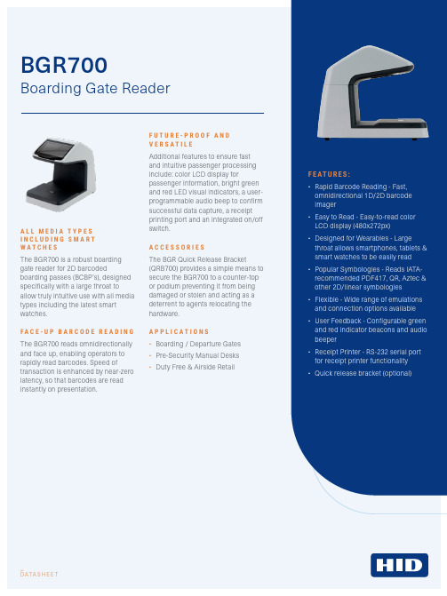
-D ATA SH E E TF E AT U R E S:•Rapid Barcode Reading - Fast, omnidirectional 1D/2D barcode imager •Easy to Read - Easy-to-read color LCD display (480x272px) •Designed for Wearables - Largethroat allows smartphones, tablets & smart watches to be easily read •Popular Symbologies - Reads IATA-recommended PDF417, QR, Aztec & other 2D/linear symbologies •Flexible - Wide range of emulations and connection options available •User Feedback - Configurable green and red indicator beacons and audio beeper •Receipt Printer - RS-232 serial port for receipt printer functionality •Quick release bracket (optional)A L L M E D I A T Y P E S I N C L U D I N G S M A R T W A T C H E SThe BGR700 is a robust boarding gate reader for 2D barcodedboarding passes (BCBP’s), designed specifically with a large throat toallow truly intuitive use with all media types including the latest smart watches.F A C E -U P B A R C O D E R E A D I NG The BGR700 reads omnidirectionally and face up, enabling operators to rapidly read barcodes. Speed oftransaction is enhanced by near-zero latency, so that barcodes are read instantly on presentation.F U T U R E -P R O O F A N D V E R S A T I L E Additional features to ensure fast and intuitive passenger processing include: color LCD display forpassenger information, bright green and red LED visual indicators, a user-programmable audio beep to confirm successful data capture, a receipt printing port and an integrated on/off switch.A C C E S S O R I E S The BGR Quick Release Bracket(QRB700) provides a simple means to secure the BGR700 to a counter-top or podium preventing it from being damaged or stolen and acting as a deterrent to agents relocating the hardware.A P P L I C A T I O N S•Boarding / Departure Gates •Pre-Security Manual Desks •Duty Free & Airside RetailBGR700Boarding Gate ReaderNorthAmerica:+15127769000|TollFree:180****7769Europe, Middle East, Africa: +44 1440 714 850Asia Pacific: +852 3160 9800 | Latin America: +52 (55) 9171-1108For more global phone numbers click here© 2023 HID Global Corporation/ASSA ABLOY AB. All rights reserved.Part of ASSA ABLOYBGR700BGR700READING CAPABILITIESBarcode ReadingCompliance: AEA20121D symbologies: Code 128, Code 2 of 5, Interleaved 2 of 5, IATA 2 of 5, Code 39, EAN2D symbologies: IATA resolution 792, PDF417, Aztec, Datamatrix and QR codes. Will also read from PDA and smartphone displaysPerformance: Less than 1 second read capabilityConstruction: Compact and durable ABS enclosure with no moving partsPassenger & AgentDisplayDisplay: Color LCD (480 x 272)Visible/audible: Green (good read) and red (bad read) indicator beacons and audio beeper Programmable capabilityCommunications & HostHost interface: RS-232C Baud rates 9600, 19200, 38400 & 1152003 x USB PortsOther: RJ45 port for optional RP9000 receipt printer, keypad or auto boarding gate applications The receipt printer can print seat, flight and passenger data from M1 format bar code documents Protocols SupportedAirIT Ease ®Amadeus ACUS ®ARINC iMuse & VMuse ®Embross CUPPS SABRE EGR ®SITA Airport Connect ®Materna CUSE ELECTRONICPowerInput voltage: 9-15VDC; AC universal power adapter supplied PHYSICALDimensions 5.3 x 8.4 x 7 in(135 × 214 x 178 mm) Scan OrientationFace-up document readingConstructionRobust PC/ABS enclosure with no moving parts Weight3 lbs. (1215g)Cable Length Approx. 6.5 ft (2 m)THERMAL (AIR)TemperatureOperating 32°F to 122°F ( 0°C to 50°C)Storage 32°F to 140°F (0°C to 60°C)Humidity0-95% non-condensing APPROVALSFCC 47CFR Part 15 Subpart B Class A (RS232 version only), EN 55022 Class A / Class B, EN 55024, FCC 47CFR Part 15 Subpart C (RS232 version only), ETSI EN 302 291EN 60950-1, IEC 62471: 2006 - Exempt Class2023-03-03-eat-bgr700-boarding-gate-reader-ds-en PLT-06266F E AT U R E SConnection TypesTechnologyQR/BarcodeRS232USB。
MESAS PIZZA 700 PIZZA COUNTER 700 产品说明书

MESAS PIZZA 700PIZZA COUNTER 700M o d .M R 70-135M R 70-180M R 70-225M F P 70-180M F P 70-225COD.DENOMINACION DENOMINATION 1111116010010006COMPRESOR COMPRESSOR 1116010010005COMPRESOR COMPRESSOR 1116010010008COMPRESOR COMPRESSOR 126010010010RELÉ DE ARRANQUE COMPRESOR COMPRESSOR STARTER CONNECTION 111126010010024RELÉ DE ARRANQUE COMPRESOR COMPRESSOR STARTER CONNECTION 136010010042CONDENSADOR DE ARRANQUE COMPRESOR CAPACITOR OF TAKE-ON 111136010010018CONDENSADOR DE ARRANQUE COMPRESOR CAPACITOR OF TAKE-ON 146010050001VENTILADOR UNIDAD CONDENSADORA CONDENSER UNIT FAN 1111156010020001CONDENSADOR CONDENSER 111156010020007CONDENSADOR CONDENSER 166010270002FILTRO SECADOR 40 GR 1/4 X 1/4DRYING FILTER 1111176010240049BANDEJA EVAPORACIÓN AUTOMÁTICA PLASTICO AUTOMATIC EVAPORATION TRAY 1111186009990780SERPENTIN EVAPORACION AUTOMÁTICA AUTOMATIC AVAPORATION COIL 1111196010700551REJILLA CUADRO DE MANDOS INOX 427X645INOX GRID SWITCHBOARD 11111106010520097SOPORTE REJILLA CUADRO DE MANDOS SWITCHBOARD DOOR HINGE 22222116010520019ESCUADRA AMARRE REJILLA CUADRO DE MANDOS TIE SQUARE SWITCHBOARD GRID 11111126010240106BASE CUADRO DE MANDOS PANEL SUPORT 11111136010240107CARATULA CUADRO DE MANDOS PANEL COVER 11111146015520103PROTECCIÓN CUADRO ELÉCTRICO ELECTRIC PANEL PROTECTION 11111156010370020CONTROL DIGITAL 1 RELE DIGITAL CONTROL FOR REFRIGERATION 11111166010310009INTERRUPTOR GENERAL ON / OFF GENERAL SWITCH ON / OFF 11111176010240105TAPON HUECO INTERRUPTOR SWITCH HOLE STOPPER 11111186010310011PILOTO COMPRESOR COMPRESSOR RUNNING LIGHT 11111196010330020PEGATINA LOGOTIPO LOGOTYPE 11111206010370030SONDA TERMOSTATO NTC THERMOSTAT PROBE 11111216010030084EVAPORADOR TIRO FORZADO EVAPORATOR 1111216010030094EVAPORADOR TIRO FORZADO EVAPORATOR 1226009991504TUBO CAPILAR CAPILLARY TUBE 111226009991500TUBO CAPILAR CAPILLARY TUBE 11226009991507TUBO CAPILAR CAPILLARY TUBE 11236010050003VENTILADOR EVAPORADOR EVAPORATOR FAN 11111246010240078GAVETA TIRO FORZADO MESA FRÍA DRIPING TRAY 11111256010240026REJILLA PROTECCIÓN VENTILADOR PROTECTION OF FAN EVAPORATOR 11111266010240016DESAGÜE 1/2" CORTO GENERAL SWITCH ON / OFF 11111296009990002 JUEGO GUIAS "U" 550 mm 550 mm SLIDE PAIR "U" 2 3 4 2 3306010350006 PARRILLA GN 1/1 PLASTIFICADA LAMINATED GN 1/1 SHELF 2 3 4 23326009990218CREMALLERA DELANTERA MESA FRÍA LEAD SUPPORT 46868336009990225CREMALLERA LATERAL TRASERA MESA GN 1/1REAR LATERAL SUPPORT 22222346009990226CREMALLERA CENTRAL TRASERA MESA GN 1/1REAR CENTRAL SUPPORT 12312356015510261DECORATIVO 1344x45 MESA GN1/1 AP DERECHA INOX DECORATIVE RIGHT OPENING 13441MESAS PIZZA 700PIZZA COUNTER 700M o d .M R 70-135M R 70-180M R 70-225M F P 70-180M F P 70-225COD.DENOMINACION DENOMINATION 11111356015510262DECORATIVO 1794x45 MESA GN1/1 AP DERECHA INOX DECORATIVE RIGHT OPENING 179411356015510263DECORATIVO 2244x45 MESA GN1/1 AP DERECHA INOX DECORATIVE RIGHT OPENING 224411356015510253DECORATIVO 1344x45 MESA GN1/1 AP IZQUIERDA INOX DECORATIVE LEFT OPENING 13441356015510254DECORATIVO 1794x45 MESA GN1/1 AP IZQUIERDA INOX DECORATIVE LEFT OPENING 179411356015510255DECORATIVO 2244x45 MESA GN1/1 AP IZQUIERDA INOX DECORATIVE LEFT OPENING 224411366009990047COSTADO LADO GRUPO INOX 635x725 MRG MCG MOTOR PANEL 11111376010560035BASE LATERAL 600x100LATERAL BASE SUPPORT COLD TABLE SNACK 11111386009990360CONJUNTO PATA Ø50X107 / 147LEG Ø50X107 / 14744444426010660018ENCIMERA GRANITO 1350x700x30GRANITE WORKTOP 1350x700x301426010660019ENCIMERA GRANITO 1800x700x30GRANITE WORKTOP 1800x700x3011426010660020ENCIMERA GRANITO 2250x700x30GRANITE WORKTOP 2250x700x3011446010700504PUERTA INOX CURV 435x640 AP DER MESA SNK/PAST REF INOX CURVED DOOR 435x640 RIGHT OPENNIG 23423446010700506PUERTA INOX CURV 435x640 AP IZQ MESA SNK/PAST REF INOX CURVED DOOR 435x640 LEFT OPENNIG 23423456010220028BURLETE 400X605 UR-260-M GASKET 400x605 UR-260-M 23423466010240109TAPETA SUPERIOR BR7UPPER COVER BR723423476010240110TAPETA INFERIOR CR7LOWER COVER CR723423486010240007SOPORTE SUPERIOR PUERTA AP IZDA UPPER HINGE LEFT OPENING 23423496010240014SUPLEMENTO BISAGRA HINGE SUPLEMENT 23423506010280001EJE SUPERIOR ø10x44UPPER GUIDE ø10x4423423516010280002MUELLE RECUPERADOR SPRING 23423526010240008TAPON SUPERIOR UPPER STOPPER 23423536010240009TAPON INFERIOR CUÑA AP IZDA LOWER STOPPER 23423546010280003EJE INFERIOR ø10x33LOWER GUIDE ø10x3323423556010240010SOPORTE INFERIOR CUÑA AP IZDA LOWER HINGE 23423576010350058REJILLA ALAMBRE TRASERA MOTOR MOTOR BACK GRIDE 11111586009992049CAJON NEUTRO 700DRAWER 77596009992046FONDO INOX PERFORADO INOX GRIDE 77606010280034JUEGO GUIAS CAJÓN NEUTRO SLIDES PAIR 616010660028PETO TRASERO GRANITO 1310x120x20SPLASH BACK 1310x120x201616010660029PETO TRASERO GRANITO 1760x120x20SPLASH BACK 1760x120x2011616010660030PETO TRASERO GRANITO 2210x120x20SPLASH BACK 2210x120x2011626010660022PETO LATERAL GRANITO 700x120x20SPLASH BACK 700x120x2022222。
Series 700 800 重型混合器说明书

We gave this series the capacity to drive long overhung mixer shafts without steady bearings. We gave it the stamina to withstand severe bending and high-torque loads imposed by fluid forces in the tank. And that’s something you can’t expect from the large general purpose drives not designed for mixing, which others use. We make shafts for 700/800 mixers larger and stronger. We size the bearings far in excess of AGMA requirements. We conduct extensive research to document the limits of shaft and impeller performance under all service conditions.As a result, you get longer service life with less maintenance. Y ou get our performance guarantee. Y ou get a mixer with an enviable track record, written by the thousands of 700/800 mixers produced in our state-of-the-art plant. Y ou’ll find our 700/800 mixers atop huge fermentation tanks in pharmaceutical production and in all manners of large scale chemical processing. Y ou’ll also find them in the dust and rock of minerals processing, as well as in the heavy sludge of waste treatment. Series 700/800 come in five case sizes, covering the range from 18.5kW to 1000kw (25HP to 1250HP). Both double and triple reduction drives are available, covering the full range of standard AGMA speeds from 230 rpm down to 11.4 rpm.PR OD U CT B E N E FITS AN D FEATU R E S• F ull Spectrum of Impellers to Optimize Results: Included are the A310 for flow-controlled applications, the A320 for high-viscosity requirements, the A315 for handling gas alone or gas and solids together, as well as the A6000 for applications requiring the special benefits of composite construction.• G uaranteed Performance: T ogether, we design your rugged 700/800 mixer, selecting impeller type, shaft length and other specifications to optimize process results. Then, we guarantee your Lightnin Mixer to perform the job for which it is recommended.• T ested 100%: Every large Lightnin mixer drive is tested under load on an advanced dynamometer. T est check gear contact patterns, noise readings, thermal data and lubrication. We welcome you to watch us test your mixer. Our goal always: Deliver factory-assembled, ready-to-go packaged units with interchangeable parts that will provide you the most efficient performance at the best possible cost.The Biggest, Heaviest Duty Standard Drives Made Specifically for MixingSPX FLOW, Inc. (NYSE:FLOW) is a leading manufacturer of innovative flow technologies, many of which help define the industry standard in the market segments they serve. From its headquarters in Charlotte, North Carolina, it operates a sales and support network, centers of manufacturing excellence, and advanced engineering facilities, throughout the world. Its cutting-edge flow components and process equipment portfolio includes a wide range of pumps, valves, heat exchangers, mixers, homogenizers, separators, filters, UHT, and drying technology that meet many application needs. Its expert engineering capability also makes it a premium supplier of customized solutions and complete, turn-key packages to meet the most exacting of installation demands.Incorporating many leading brands, SPX FLOW has a long history of serving the food and beverage, power and energy, and industrial market sectors. Its designs and engineered solutions help customers drive efficiency and productivity, increase quality and reliability, and meet the latest regulatory demands. In-depth understanding of applications and processes, state-of-the-art Innovation Centers, and advanced pilot/testing technology further assist in optimizing processes and reducing timescales to reliably meet production targets.T o learn more about SPX FLOW capabilities, its latest technology innovations and complete service offerings, please visit .A World Leader in Industrial Mixing since 1923, Lightnin has 90 years of unrivaled experience in industrial mixing technology, process knowledge, and technological innovation. Lightnin enjoys a global reputation for durable, long-lasting mixers, agitators, aerators, and flocculators for fluid process systems. We offer a full spectrum of impeller designs for diverse applications. In addition, we offer a worldwide service network, mixer repair, gearbox repair, and replacement parts programs. Look to Lightnin for knowledge, technology, and service excellence.3Flex ProtectionGears in all 800 series units like this one are protected from mixer shaft bending loads by the Lightnin hollow quill flex protection. Quill and shaft mixer are mounted on separate bearings. A torsionally resilient coupling transmits power from quill to mixer shaft, while isolating gearing from shaft flexure.Splash LubricationOn sizes up to 783/883, gears dipping in an oil sump provide a constant flow of oil to all surfaces.Covered For SafetyPersonnel are protected from rotating parts by guards that meet OSHA requirements. All mounting flanges are designed to ASME Unfired Pressure Vessel Code.Rugged Motor MountA heavy-duty channel base is the standard motor mount for Series 700/800.Quiet-Running GearsAll helical gears are carburized and ground. The highly efficient spiral bevel gear and pinion are match-lapped as a set to assure smooth, quiet operation.Beyond AGMABearings are sized far beyond AGMA requirements to minimize maintenance and provide long service life.A510: General Purpose New laser-designed impel-ler delivers true axial flow, high flow-per-horsepower, and can be custom-fit to your application.A320: High-Viscosity Fluid foil design reduces blend time by half anddelivers better axial motion for 50% power savingcompared to conventional pitch-blade turbines.A315: Gas-Liquids-Solids Improves yield by up to 50% in shear-sensitive processes such as fermentation. The A315 is the optimum impel-ler for applications involving mass transfer and solidssuspension.A6000: Low ViscosityFor flow-controlled applications in hostile environments. Main-tains flow and reduces power to 45% of conventional pitched-blade impellers. Structural composite is lightweight and extremely resistant to corrosion.TH E ORY OF OPE RATI ON:Features available on units up to 1000kW (1250HP)H I G H-E FFI CI E N CY I M PE LLE R S TO MATCH YOU R PR OCE S S N E E D S:Oil DamLeakage down the mixer shaft is positively prevented by an oil dam around the quill shaft.LightninLube™As part of our commitment to our Customers and their operations, SPX has introduced LightninLube™, a range of gear oil for our Lightnin Mixers. It is available to order with your new equipment or as a maintenance item throughout the life of your equipment.LightninLube is manufactured to AGMA Standard 8005-D94. Our synthetic oils are designed to give you a wide operating range and are available in ISO 100, ISO 150, ISO 220 and ISO 320 grades.Contact our Service department or your Sales Representative to discuss your needs.S U PP ORT F OR H EAVY M I X E R SLarge Series 700/800 mixers are optimally supported independently from the mixing tank. Mixers of closed tank configuration can be mounted on their own beams or on the plant floor above the tank. Either way, only a separate seal or stuffing box need be mounted on the tank and supported by it.Mounting on upper floor. Note how hydraulic lifts can simplify servicing the seal.TE CH N I CAL S E RVI CE SWith more than 90 years experience in the manufacture and supply of agitation equipment, we know what parts need to be on hand to support our customer base so that your downtime is minimized. The Lightnin brand after sales support teams are on call to offer advice, support on-site installation and commissioning, servicing of equipment, or super-vise and train your maintenance staff in best practice care of equipment.S E RVI CE S U PP ORT & R E FU R B I S H M E NT The equipment audit is specifically designed to identify potential mechanical problems before they occur. Using many forms of modern technology and drawing on our mixer manufacturing experience, our technicians can identify the onset of bearing and gear failures, misalign-ment and system problems without the need to interrupt production. Factory gearbox exchange and refurbishment programs offer a fastand cost-effective route to extending equipment life.USA13320 Ballantyne Corporate Place Charlotte, NC 28277United States of America +1 704 752 4400CH I NA7F Nanfung T ower 1568 Hua Shan Road Shanghai 200052 China P: +86 (21) 22085889UKOcean House, T owers Business Park Didsbury, Manchester M20 2L Y, UKP: +44 161 249 1170SPX FLOW, Inc. - Global locationsS PX FLOW, LLC - LI G HTN I N & PLE NTY M I X E R S135 Mt. Read Blvd.Rochester, NY 14611P: +1 (888) 649-2378 (MIX-BEST), (US and Canada) or +1 (585) 436-5550F: +1 (585) 436-5589E:********************•/lightninSPX FLOW, Inc. reserves the right to incorporate our latest design and material changes without notice or obligation.Design features, materials of construction, and dimensional data, as described in this bulletin, are provided for your information only and should not be relied upon unless confirmed in writing. Please contact your local sales representative for product availability in your region. For more information, visit . The green “” and “” are trademarks of SPX FLOW, Inc.LIG_700/800_B-656_US Version: 03/2019 COPYRIGHT © 2019 SPX FLOW, INC.For other Sales locations, click/lightnin\contacts\where-to-buy\or use your SmartPhone and the QR Code.。
预设定机油枪使用说明书(中文)

路博预设定机油枪使用说明书中文试用版警告: 在操作之前请仔细读和理解用法说明。
没有按照安全规章和其他基本安全预防措施操作可能导致严重人为事故。
使用说明预设定机油枪被设计用于机油的输送,当设定的油量到达时,喷嘴会自动关闭,停止机油输送。
技术参数流量范围 1 – 35 LPM (0.3-9.2 GPM)操作压力范围0.5 – 70 Bar (7-1000 PSI)操作温度Max. 60°C (140°F)精度±0.5%粘性8-5000 mPas5-Digital LCD Display (3/8"H xQuart, Pint, Gallon, Liter3/16"W) 数显单位接头1/2" BSP电源电压 1 Alkaline cell 9V操作数字表设备使用9V可更换的碱性电池,对于电池的更换请查看说明书D部分。
1、按键按数字直接设置AUTO按AUTO进入或退出自动模式RESET在手动或自动模式清除之前的设置OK/STOP按OK键确认动作或停止动作2、安装A. 安装前的准备工作1)系统压力的释放a) 关闭泵电源或截止阀b) 慢慢地打开枪的出油口处的油路截止阀,放出系统中的油到废油容器中,进行排油c)打开系统中所有的油路截止阀,启动油泵开始向系统供油d)让油泵处于打开状态,确保系统回路压力平衡2) 关闭截止阀3) 绕管装置根据场地,为了节约空间,用户需要配置下面设备,系统中的每个装置应进行有效的接地:a) 泵:依据生产厂家推荐的方法执行b)空气和流体软管:进行有效接地c)空气压缩机:依据生产厂家推荐的方法执行d) 油桶:使用当地允许型号的油桶警告不要在管连接处用特富龙胶带,可能导致接地效果失效B. 仪表连接软管在开始操作之前关闭油泵喷嘴与仪表连接3. 仪表的操作根据需要的功能选择不同的操作选项按AUTO键,液晶屏上会显示AUTO标示按OK/STOP键,为确定或停止按RESET键从菜单或已经进行的操作中退出,可以立即进行其他操作A. 显示模式仪表开始工作前按RESET键进行清零仪表显示即时当前计注值显示存储总值按RESET键可以上排计注值清零仪表将显示如下警告存储总值默认不可被改动,如果要更改,请联系服务中心权威扣下扳机进行加油放开扳机停止加油B. 操作模式B-1.手动模式按RESET进入手动模式仪表显示手动模式扣下扳机进行加油,当到所需的油量时,释放扳机,停止加油按RESET键清零B-2. 自动模式按AUTO仪表显示1-2-3-4-last :5组预存设定值可被频繁使用。
百诺血糖仪GM700SB说明书
TM The Rightest Blood Glucose Monitoring System GM700SB is a personal blood glucose monitoring system to be used for self-testing only. It is not allowed for muitiple users.The testing result is calibrated to be plasma equivalent for test with fresh capillary, venous, arterialand neonatal whole blood samples. Capillary samples may be drawn from the fingertip, palm and forearm, and in the case of neonates, the heel. You may consult your healthcare professional for instructions on how to use the system correctly. Our customer support staff is available to assistyou as well.A healthcare professional should be contacted when Customer Service is not available. Please forward your warranty card to customer support to activate your warranty coverage.TM The Rightest Blood Glucose Monitoring System GM700SB is manufactured and supported byBionime Corporation. If you have any questions or concerns, please contact your local Bionime ********************************************.TM Thank you for selecting the Rightest Blood Glucose Monitoring System GM700SB. This manual provides all the information you need to operate this product for accurate test results. Please read this entire manual before you start any testing.For people living with diabetes, it is important to regularly monitor blood glucose levels to effectively TM reduce complications from the disease. The easy-to-use Rightest Blood Glucose Monitoring System GM700SB provides accurate, reliable test results to help you better manage your diabetes. TM The Rightest Blood Glucose Monitoring System GM700SB is designed for in vitro diagnostic use only (for self-testing by a single user outside the body). T esting requires only a small amount of fresh capillary whole blood from either the fingertip, palm or forearm.Venous, arterial, and neonatal blood testing is limited to healthcare professional use only.- Before using the Blood Glucose Monitoring System to test your blood glucose, please read all of the instructions and conduct all of the tests including the quality control test (Refer to page 42). - Please perform the quality control test regularly to make sure the test results are accurate.TM TM - The Rightest Meter GM700SB can only be used with Rightest T est Strips GS700. Other brands’ test strips should not be used under any circumstances. The use of other brands’ strips may give inaccurate results.TM - The Rightest System GM700SB is intended for in vitro diagnostic use only. The test resultsusing fresh capillary whole blood samples from the fingertip, palm and forearm are calibrated to be equivalent to plasma testing.- Venous, neonatal or arterial blood testing should be performed by healthcare professionals.TM - The Rightest System GM700SB is intended for self-testing. It should not be used to diagnose diabetes mellitus.TM - If the Rightest Meter and T est Strips are exposed to a substantial change in temperature, please wait 30 minutes before measurement.- Follow all environmental protection regulations when disposing of batteries.- You may manually turn off the Bluetooth when you are in the radio-restricted area (like on the airplane).TM Rightest GM700SB - Avoid contact with dripping or splashing liquids.TM - The minimum blood sample size to test using the Rightest Blood Glucose Monitoring System GM700SB is 0.75µL: ( )Blood sample size above 3.0µL might contaminate the test strip port and the meter.Blood sample size below 0.75µL may cause an inaccurate result or may prevent a meter reading. An Er4 reading will be displayed if the sample size is too small. In this case, repeat the test with a new test strip.Sample Size Example Important Safety Notes:- All parts of the kit are considered biohazardous and can potentially transmit infectious diseases, even after following the cleaning and disinfecting procedures. Please refer to the section " Caring for Your Meter" on page 48.- Users should wash their hands thoroughly with soap and water before and after handlingthe meter, lancing device, or test strips.Understanding Test Results and Messages......................................................................................Quality Control About Quality Control T esting.............................................................................................................Performing a Quality Control T est.......................................................................................................Understanding Control T est Results...................................................................................................Test Memory Recalling T est Results........................................................................................................................Recalling Average T est Results..........................................................................................................Caring for Your Meter...........................................................................................................................Error Messages and Troubleshooting................................................................................................Limitations..........................................................................................................................................Specifications.....................................................................................................................................Warranty..............................................................................................................................................Customer Service...............................................................................................................................Expected Blood Glucose Values Without Diabetes........................................................................... .Component Manufacturer Information.. (484953)5456575859383942444546About the Blood Glucose Monitoring System The Blood Glucose Monitoring System .........................................................The Blood Glucose Meter ..............................................................................The Blood Glucose T est Strip ..............................................................................Before Testing Meter Activation and Battery Change...............................................................................................Setting Up Your Meter - Setting the Date, Time and Volume.............................................................T urning On/Off the Meter....................................................................................................................Handling the Blood Glucose Test Strip ..............................................................Testing ProcedureGetting Ready for T esting...................................................................................................................Performing a Blood Glucose T est.......................................................................................................Upload Data T urn On / Off Bluetooth Alternative Site Testing.......................................................................................................................View Window Appearance.................................................................................................................TM Rightest TM Rightest TM Rightest TM Rightest TM Rightest GM700SB GM700SB GM700SB GS700GS700 Setting Markers.. (810)1416 18 222325262732333436ContentsYour Blood Glucose Monitoring System GM700SB consists of several items. Please identify each item, learn its name and how it is used. Below are the items included in your Blood Glucose Monitoring System GM700SB:1. Getting Started Guide2. User's Manual (includes Log Book, Warranty Card, Emergency Card )3. Blood Glucose T est Strip GS700 Package Insert *4. Control Solution GC700 Package Insert *5. Blood Glucose Meter ( with 1 CR2032 battery installed )6. Blood Glucose T est strips GS700 ( 10/25 pcs )*7. Control Solution GC700 *(Normal Level is provided in your starter kit )8. Lancing Device *9. Clear Cap *10. Disposable Sterile Lancets ( 10 pcs ) *11. Carrying Case ( not shown )*12. Instruction for the lancing device ( not shown )*13Instruction for mobile App (not shown)(* Different packages have different bundled items. Some of packages might not include * items.)TM Rightest TM Rightest TM Rightest TM Rightest TM Rightest TM Rightest TM Rightest TM Rightest GM700SB . NOTE- GM700SB can concomitant use with mobile App, please refer to the "Instruction for mobile App" for detailed information.4. The Blood Glucose Meter5. Press any button under any picture to exit the self-test and enter Setting Mode.TM Rightest replacing the battery (all symbols will appear on the screen).6. You must set the time and date when replacing the battery. See Chapter “Setting Up Your Meter - Setting the Date, Time, and Volume" on page 18. T est results are still stored in the memory. GM700SB will enter Self-T esting Mode automatically when 1000You can enter the Setting Mode two ways.1. Replace the Battery2. With Battery InsertedAfter removing the battery, press the main button several times until there is no signal on screen, TM then follow the battery installation steps to replace battery. The Rightest Blood Glucose Meter will perform a self-test. Press the main button to exit the self-test and enter the Setting Mode.When the meter is “ON”, hold down the main button for 7 seconds. During this time the screen will go blank until you hear a beep. After the beep, the meter will turn on into the Setting Mode. The display screen will show setting data.GM700SBNOTE- If you do no change any settings during Meter Set-up for over 2 minutes, the BloodGlucose Meter will leave setting mode - and power off automatically.- Meter default is set according to your local preference.TM Rightest GM700SBAccording to actual life status, you can set meal markers with test result.You have to perform meal marker setting before testing.1. Before test, press the Left or Right button to choose between the “ ”(before meal), ” ”,2. If you don't set the marker in 15 seconds, the default marker will be " ".the screen. Pressing the Right button to choose between the before meal),”on). Apply the blood sample within 2 minutes. press the release button.will not start. If the blood sample was insufficient, discard the test strip and repeat with a new Blood Glucose T est Strip GS700.“NOTEUser should turn off meter or meter’s Bluetooth while traveling in flight. User canstill perform blood glucose testing while the Bluetooth function is off.funcionPlease follow your airline flight safety instruction.Bluetooth is always ON and when mobile App turn on, it will automatically pair with your mobiledevice.Once the connection successfully pairs, test results will start uploading to the connected mobiledevice.When the test result uploading has completed, Bluetooth will disconnect from mobile Appautomatically.The GM700SB meter is now uploading testresults to your mobile device.Turn off Bluetooth functionPress on the right or left button for 2 seconds to turn off the Bluetooth function." will not be shown on the screen.Turn on Bluetooth functionPress on the right or left button for 2 seconds to turn on the Bluetooth function." will flash on the screen.Make sure your blood sample covers the wholearea of the view window to get an accurate testresult. An insufficient blood sample will result inan error message ("Er4"). If this occurs, repeatthe test with a new test strip.Insufficient blood sample Sufficient blood sample2. Use either the Left or Right button on the side to review all previous resultswith date and time. Results display from the most recent (Sequence no. “1”)to the oldest (Sequence no. “500”) in the lower right hand corner of thescreen.3. The Quality Control T est result can be recalled from the saved data. When" appears next to the data, the test was performed by the Control Solution GC700. The control solution test result will not be used whenrecalling test average results.TM "RightestNOTE - T est results must existduring the desired time interval. For example: T o get a 14-day average on 1/30/11, you must have test results dated between 1/17 and 1/30. If no test results exist during thattime frame you will not receive an average.- The "Lo ", "Hi " results, control solution test results and test results under abnormaltemperature < 6°C (43°F), > 44°C (111°F) will be excluded from average calculations.The Average function requires that the correct time and date is set .1. Press the Main button to switch the screen to Average Mode.2. On the average screen, use either the Left or Right button to view 1-day, 7-days, 14-days, 30-days, 60-days or 90-days averages.3. The number shown in the lower right hand corner indicates how many test results have been calculated.TM- Rightest Blood Glucose Monitoring System GM700SB is not intended for serum or plasma testing.- Inaccurate test results may be obtained at altitudes greater than 10,000 feet (3048 meters) above sea level.- Severe dehydration and excessive water loss may cause inaccurately low results.- The glucose test may be invalid in the presence of abnormally high concentration:Ascorbic acid ≧5 mg/dL (0.28 mmol/L), Xylose ≧20 mg/dL (1.33 mmol/L) and Uric Acid ≧20 mg/dL (1.19 mmol/L).- Not for screening or diagnosis of diabetes mellitus.- Not for use on critically ill patients in shock, dehydrated patients or hypo-osmolar patients.- Alternative site testing (AST) should only be performed during steady-state times (when glucose is not changing rapidly).- Alternative site testing should not be used to calibrate continuous glucose monitoring systems (CGMS).- Alternative site testing should not be performed if testing for hypoglycemia (Low blood glucose). - Results from alternative site testing should not be used in insulin dose calculation.- Regarding potential electromagnetic or other interference, keep meter out of electromagnetic radiation sources.We sincerely like to provide complete, considerate services to our customers. Please review all the instructions to make sure you are performing the steps correctly. If you have any questions or in case of problems with the products, please contact your local Bionime customer service or email **********************.。
迈克洛雷兹埃尔700生成器说明书
User ManualT ABLE OF C ONTENTS1. Before You Begin (3)What Is Included (3)Unpacking Instructions (3)Claims (3)Text Conventions (3)Symbols (3)Disclaimer (3)Product at a Glance (4)Safety Notes (4)2. Introduction (5)Overview (5)3. Setup (6)AC Power (6)Fuse Replacement (6)Mounting (7)Orientation (7)Rigging (7)4. Operation (8)Using the Wired Remote (8)5. Technical Information (9)Fogger Maintenance (9)Storage (9)6. General Troubleshooting (10)7. Technical Specifications (11)Returns (12)Contact Us (13)Page 2 of 13 Hurricane™ 700 User Manual Rev. 101.B EFORE Y OU B EGINWhat Is Included ·Hurricane™ 700·Fog Fluid (1 pint)·Power Cord·Warranty Card·Quick Reference Guide·Permanently Wired RemoteUnpacking Instructions Carefully unpack the product immediately and check the container to make sure all the parts are in the package and are in good condition.Claims If the box or the contents (the product and included accessories) appear damaged from shipping, or show signs of mishandling, notify the carrier immediately, not Chauvet.Failure to report damage to the carrier immediately may invalidate your claim. Inaddition, keep the box and contents for inspection.For other issues, such as missing components or parts, damage not related to shipping,or concealed damage, file a claim with Chauvet within 7 days of delivery.Text Conventions Convention Meaning1 to 512 A range of values50/60 A set of values of which only one can be chosenDisclaimer The information and specifications contained in this User Manual are subject to change without notice. Chauvet assumes no responsibility or liability for any errors or omissions,and reserves the right to revise or recreate this manual at any time. Download the latestversion from .© Copyright 2014 Chauvet. All rights reserved.Electronically published by Chauvet in the United States of America.Author Date Editor DateA. Leon 10/21/14 M. Trouard 10/21/14Hurricane™ 700 User Manual Rev. 10 Page 3 of 13Page 4 of 13 Hurricane™ 700 User Manual Rev. 10These notes include important information about the mounting, usage, and maintenanceof this product; read before using the product.·Always connect the product to a grounded circuit to avoid the risk of electrocution.·Always disconnect the product from the power source before cleaning or replacing the fuse.· Make sure the power cord is not crimped or damaged.· Never disconnect the product from power by pulling or tugging on the cord. · If mounting the product overhead, always secure to a fastening device using a safety cable.· Make sure there are no flammable materials close to the product when operating. · Do not touch the product’s housing when operating because it may be very hot. · Do not mount the product on a flammable surface (linoleum, carpet, wood, paper, carton, plastic, etc.).· Do not touch the output nozzle on this product. It is very hot during operation and it may remain hot for several hours after turning the product off.· The fog exits the nozzle at a very high temperature. Keep a minimum distance of 6.5 ft (2 m) from the nozzle to the nearest object.· Do not drink the fog fluid. If you do, call your local emergency service (911 in the US) for help.·Do not add perfume, alcohol, gasoline, or any other flammables to the fog fluid.· Depending on the amount of fog generated, all fog machines may set off smoke detectors.· Always make sure that the voltage of the outlet to which you are connecting the product is within the range stated on the decal or rear panel of the product. · Always install the product in a location with adequate ventilation, at least 20 in (50 cm) from adjacent surfaces.· Be sure that no ventilation slots on the product’s housing are blocked. · Never connect the product to a dimmer or rheostat.· Make sure to replace the fuse with another of the same type and rating.·Never carry the product from the power cord or any moving part. Always use the hanging/mounting bracket.· The maximum ambient temperature (Ta) is 104 °F (40 °C). Do not operate the product at higher temperatures.· In the event of a serious operating problem, stop using the product immediately. · Never try to repair the product. Repairs carried out by unskilled people can lead to damage or malfunction. Contact the nearest authorized technical assistance center. · This product is not intended for permanent installation. · Do not use for space heating purposes.· Use only CHAUVET® water-based fog fluid. · Drain the tank before transporting the product.·To eliminate unnecessary wear and improve its lifespan, during periods of non-use completely disconnect the product from power via breaker or by unplugging it.Keep this User Manual for future use. If you sell the product to another user, be sure to give this document to the next owner.FCQ (Fog Cleaner Quart) was specifically developed by Chauvet to clean your Hurricane™ 700. Make sure you use FCQ regularly, no longer than 90 days between cleanings, to increase the life of your fogger.Hurricane™ 700 User Manual Rev. 10 Page 5 of 132. I NTRODUCTIONOverviewPower InFuse HolderBack Panel ViewFog Fluid LevelIndicatorPage 6 of 13 Hurricane™ 700 User Manual Rev. 103. S ETUPAC Power The Hurricane™ 700 has a fixed voltage power supply and it can work with an inputvoltage of either 120 VAC, 60 Hz or 230 VAC, 50 Hz, depending on the specific model. To determine the product’s power requirements (circuit breaker, power outlet, and wiring), use the current value listed on the label affixed to the product’s back panel, or refer to the product’s specifications chart. The listed current rating indicates the product’s average current draw under normal conditions.Always connect the product to a protected circuit (circuit breaker or fuse). Make sure the product has an appropriate electrical ground to avoid the risk of electrocution or fire.Never connect the product to a rheostat (variable resistor) or dimmer circuit, even if the rheostat or dimmer channel serves only as a 0 to 100% switch.FuseReplacementDisconnect the product from power before replacing the fuse.1. Disconnect the product from power.2. Wedge the tip of a flat-head screwdriver into the slot of the fuse holder.3. Pry the fuse holder out of the housing.4. Remove the blown fuse from the holder.5. Replace with a fuse of the exact same type and rating.6.Insert the fuse holder back in place and reconnect power.A spare fuse is not included; however, the safety cap has room for a spare.Always replace a blown fuse with another of the same type and rating.Mounting Before mounting the product, read and follow the safety recommendations indicated in the Safety Notes.Orientation When mounting the Hurricane™ 700, make sure adequate ventilation is provided around the product.Rigging ·Before deciding on a location, always make sure there is easy access to the product for maintenance and fluid replenishment.·Make sure that the structure or surface onto which you are mounting the product can support the product’s weight (see the Technical Specifications).·When mounting the product overhead, always use a safety cable. Mount the product securely to a rigging point, such as an elevated platform or a truss.·When rigging the product onto a truss, you should use a mounting clamp of appropriate weight capacity. The bracket has an M8 size hole, which is appropriatefor this purpose.·The bracket adjustment knobs allow for directional adjustment when aiming the product to the desired angle. Only loosen or tighten the bracket knobs manually.Using tools could damage the knobs.Mounting DiagramRubber Feet (x4) for floor mountingHurricane™ 700 User Manual Rev. 10 Page 7 of 134.O PERATIONUsing the Wired Remote Trigger the Hurricane™ 700 using the included wired remote. The LED indicator on the remote indicates when the fogger has reached the required operating temperature. Press the button on the remote to momentarily output fog. The length of the wired remote is 13 ft (4m).Fill the fog fluid reservoir with CHAUVET® water-based fog fluid before operating the Hurricane™ 700.Permanently Wired RemoteMomentary Fog ButtonPage 8 of 13 Hurricane™ 700 User Manual Rev. 10Hurricane™ 700 User Manual Rev. 10 Page 9 of 135. T ECHNICAL I NFORMATIONFogger Maintenance Do not allow the fogger to become clogged. After every 40 hours of continuousoperation, use CHAUVET® Fog Cleaner Quart (FCQ) through the system to prevent theaccumulation of particulate matter in the heating element.The recommended cleaning procedure is as follows. 1. Unplug the product from power.2. Empty all fog fluid from the machine.3. Add cleaning solution to the tank.4. Connect the product to power and allow it to warm up.5. Run the unit in a well-ventilated area until the tank is almost empty. Do not allowthe pump to run dry. 6. Refill with fogger fluid to continue using the fogger. Run the machine briefly to clearany remaining cleaning solution from the pump and heater.Do not operate the machine without fluid at any time.FCQ (Fog Cleaner Quart) was specifically developed by Chauvet to clean your Hurricane™ 700. Make sure you use FCQ regularly, no longer than 90 days between cleanings, to increase the life of your fogger.StorageBefore storing the fogger, run FCQ through the system as described in the cleaning procedure above; however, only follow steps 1 through 5. Do not refill the tank with fog fluid if storing the fogger. Cleaning the system prior to storage will help prevent any particles from condensing inside the pump or heater while not in use .Test-run your Hurricane™ 700 on a monthly basis to achieve the best performance.6.G ENERAL T ROUBLESHOOTINGIf you still experience problems after trying the solutions presented here,contact Chauvet Technical Support. See Contact Us.Page 10 of 13 Hurricane™ 700 User Manual Rev. 10Hurricane™ 700 User Manual Rev. 10 Page 11 of 137. T ECHNICAL S PECIFICATIONSDimensions andWeight8.5 in (215 mm)7.1 in (180 mm)4.9 in (124 mm)4 lb (1.8 kg)Note: Dimensions in inches rounded to the nearest decimal digit.PowerModel-specific120 VAC, 60 Hz or 230 VAC, 50 HzFixedConsumption 471 W 471 WOperating current3.9 A 2.0 A FuseT 5 A, 250 VT 5 A, 250 VPower input connectorIEC IEC Power Cord plugEdison (US)Local plugOperation/Capacity/Consumption2.5 min0.2 gal (0.6 l)7.5 ml/minMisc.1500 cfmWired Remote13 ft (4 m)Thermal104 °F (40 °C)ConvectionOrderingHurricane™ 700 (120 V) 09070161 781462202941 Hurricane™ 700 (230 V)09070323781462206758Page 12 of 13 Hurricane™ 700 User Manual Rev. 10To return a product or request support:· In the U.S., contact Chauvet World Headquarters (see Contact Us ). · In the UK or Ireland, contact Chauvet Europe Ltd. (see Contact Us ). · In Mexico, contact Chauvet Mexico (see Contact Us ).·In any other country, DO NOT contact Chauvet. Contact your distributor. See for distributors outside the U.S., United Kingdom, or Ireland.If you live outside the U.S., United Kingdom, Ireland, or Mexico, contact your distributor of record and follow their instructions on how to return Chauvet products to them. Visit our website for contact details.Returns Call the corresponding Chauvet Technical Support office and request a ReturnMerchandise Authorization (RMA) number before shipping the product. Be prepared to provide the model number, serial number, and a brief description of the cause for the return.You must send the merchandise prepaid, in its original box, and with its original packing and accessories. Chauvet will not issue call tags.Clearly label the package with the RMA number. Chauvet will refuse any product returned without an RMA number.Write the RMA number on a properly affixed label. DO NOT write the RMA number directly on the box.Before sending the product, clearly write the following information on a piece of paper and place it inside the box:· Your name · Your address· Your phone number · RMA number· A brief description of the problemBe sure to pack the product properly. Any shipping damage resulting from inadequate packaging will be your responsibility. FedEx packing or double-boxing are recommended.Chauvet reserves the right to use its own discretion to repair or replace returned product(s).C ONTACT U S WORLD HEADQUARTERS - ChauvetGeneral InformationAddress: 5200 NW 108th AvenueSunrise, FL 33351Voice: (954) 577-4455Fax: (954) 929-5560Toll free: (800) 762-1084Technical SupportVoice: (954) 577-4455 (Press 4)Fax: (954) 756-8015Email: ************************World Wide Web UNITED KINGDOM AND IRELAND - Chauvet Europe Ltd.General InformationAddress: Unit 1CBrookhill Road Industrial EstatePinxton, Nottingham, UKNG16 6NTVoice: +44 (0)1773 511115Fax: +44 (0)1773 511110Technical SupportEmail: **************************World Wide Web MEXICO - Chauvet MexicoGeneral InformationAddress: Av. Santa Ana 30Parque Industrial LermaLerma, Mexico C.P. 52000Voice: +52 (728) 285-5000Technical SupportEmail: ********************.mxWorld Wide Web .mxOutside the U.S., United Kingdom, Ireland, or Mexico, contact your dealer. Follow their instructions to request support or to return a product. Visit our website for contact details.Hurricane™ 700 User Manual Rev. 10 Page 13 of 13。
博亚斯威尔金斯700系列3说明书

Welcome and thank you for choosing Bowers & Wilkins.Our founder, John Bowers, believed that imaginative design,innovative engineering and advanced technology were keys thatcould unlock the enjoyment of audio in the home. His belief is onethat we continue to share and inspires every product we design.This is a high performance product that rewards thoughtfulinstallation, so we suggest that you take some time to read thismanual before you begin. Continue on page 3Carton ContentsThe table above illustrates the component parts that are packed with the product. In the unlikely event that anything is missing please contact the retailer from whom you purchased the speakers.The tweeter assembly on 702 S3, 703 S3, 705 S3 and HTM71 S3 loudspeakers is a decoupled component that is mechanically isolated from the main part of the cabinet. As such, it may appear to be loose when the product is first removed from its packaging. This is not a fault: it is an inherent feature of the design and ensures optimum performance from your speaker.Environmental InformationThis product complies with international directives, including but not limited to:i. the R estriction of H azardous S ubstances (RoHS) inelectrical and electronic equipment,ii. the R egistration, E valuation, A uthorisation and restriction of CH emicals (REACH)iii. the disposal of W aste E lectrical and E lectronic E quipment (WEEE).Consult your local waste disposal authority for guidance on how properly to recycle or dispose of this product.34E N G L Speaker Installation702 S3 / 703 S3 / 704 S3702 S3, 703 S3 and 704 S3 are intended to be floor mountedonly. For proper stability, always install the provided plinth, thenensure that the speakers stand firmly on the floor using the spikeor rubber feet supplied.You may attach the plinth during the unpacking process, followingthe illustrations above or the diagrams on the top flap of thecarton.WarningThe plinth MUST always be used, with the rubber or spike feetinserted into the plinth. DO NOT insert rubber or spike feet directly into the cabinet.Note: Rubber feet installation is nearly identical to spike feetinstallation. The tommy bar and spanner are only includedand used with the 702 S3 model during spike / rubber feetinstallation.702 S35705 S3 / 706 S3 / 707 S3The 705 S3, 706 S3 and 707 S3 are primarily designed to be mounted on a dedicated floor stand (FS-700 S3), but may be placed on a shelf if preferred. However, it should be noted that this offers less flexibility to optimise the speaker’s performance. If shelf placement must be used, we recommend using the foam plugs (supplied) to optimise port performance (see Section 4: Fine-Tuning).In both installation cases, the speakers’ tweeters should be approximately at ear height at your usual listening position.Note: If using a shelf, ensure that it is strong enough to properly support the weight and fit the four self-adhesive rubber feet to the underside of the speaker.Important Safety NoticeSharp spikes, do not touch.The spike feet are designed to pierce carpet and rest on thefloor surface. Initially, screw the lock nuts onto the spikes justfar enough to leave the nuts floating just above the carpet whenthe spikes are resting on the floor beneath. Then, screw thespikes fully into the threaded inserts in the plinth. If the cabinetrocks when placed on the floor, unscrew the two spikes that donot touch the floor until the cabinet rests firmly without rocking.Finally, lock the nuts against the base by using the suppliedspanner to gently tighten the nut whilst using the supplied tommybar to stop the spike foot rotating. It may be more convenient tofit and adjust the spike feet after speaker positioning has beenoptimised.If there is no carpet and you wish to avoid scratching the floorsurface, use either a protective metal disc (a coin perhaps)between the spike and the floor, or use the supplied rubber feet.Fit the rubber feet and level the cabinet in the same manner aswith the spike feet.702703, 704705, 706, 7076E N GSpeaker Positioning In either stereo or home theatre installations, try to ensure that the immediate surroundings of each speaker are similar in acoustic character. For example, if one speaker is adjacent to bare walls while the other is adjacent to soft furnishings and curtains, both the overall sound quality and the stereo image are likely to be compromised.Conventional Stereo SystemsTo begin with, the speakers should be positioned between 1.5mand 3m apart at two corners of an equilateral triangle completedby the listening area at the third corner. The speakers should beplaced at least 0.5m away from the back and any side walls (asper the illustration above).HTM71 S3 / HTM72 S3If using a projection television with an acoustically transparentscreen, position the speaker behind the centre of the screen.Otherwise, position it either directly below or above the screenusing either a floor stand, furniture unit or wall shelf, ensuring thespeaker is as close to ear height as possible. If the speaker isto be placed either on a shelf or in a rack shared with other AVequipment, fix the four self-adhesive rubber feet to the base ofthe speaker. They provide a degree of vibration isolation.7Home Theatre SystemsIf the speakers are to be used for the front channels in a hometheatre system, they should be placed closer together than for2-channel audio, because the surround channels tend to widenthe image. Positioning the speakers within approximately 0.5mof the sides of the screen will also help keep the sound imagein scale with the visual image. As with conventional stereopositioning, the speakers should ideally be at least 0.5m awayfrom any side walls.Stray Magnetic Fields The speaker drive units create stray magnetic fields that extend beyond the boundaries of the cabinet. We recommend you keep magnetically sensitive articles (CRT television and computer screens, computer discs, audio and video tapes, swipe cards and the like) at least 0.5m from the speaker. LCD, OLED and plasmascreens are not affected by magnetic fields.5 Channels 7 Channels8Important Safety NoticeAll connections should be made with the audioequipment switched off. When using audio equipmentin normal operation, touching uninsulated speakerterminals or wiring may result in an unpleasant sensation. The700 S3 speaker terminals accept a variety of cable terminations:4mm banana plugs, 6mm and 8mm (1/4 in and 5/16 in) spades, or bare wires up to 4mm (5/32 in) diameter.Important Safety NoticeIn certain countries, notably those in Europe, the useof 4mm banana plugs is considered a potential safetyhazard, because they may be inserted into the holesof unshuttered mains supply sockets. In order to comply withEuropean CENELEC safety regulations, the 4mm holes in theends of the terminals are blocked by plastic pins. If you are usingthe products in any country where these conditions apply, youshould ensure that any banana plugs cannot be used in an unsafemanner by children or other uninformed persons. The plastic pins can be removed if you wish to use banana plugs. Ask your dealer for advice when selecting speaker cable. Keep its total impedance below the maximum recommended in the speaker specification and use a low inductance cable to avoid attenuation of high frequencies.There are two linked pairs of terminals on the back of the speaker. For conventional connection (above left), the terminal links should remain in place (as delivered) and just one pair of terminals connected to the amplifier. For bi-wire connections or bi-amplification (above right), the terminal links should be removed and each pair of terminals connected to the amplifier or amplifiers independently. Bi-wiring can improve the resolution of low-level detail.Ensure that the positive terminals on the speaker (with red ring) are connected to the positive output terminal on the amplifier and the negative terminals on the speaker (with black ring) are always connected to the negative output terminal on the amplifier. Incorrect connection will not result in damage but will cause poorstereo imaging and loss of bass. Always screw the terminal capsdown fully to prevent rattles.3. Connections-L F-L F Conventional ConnectionBi-Wired Connection9If no alternatives exist, you can adjust your loudspeakers’ low-frequency performance using the supplied foam plugs. The plugs are a two-piece part, allowing for a degree of fine-tuning using either the outer, larger-diameter piece in isolation or the two parts together. Using solely the outer, larger-diameter foam piece will deliver less bass attenuation than the complete plug assembly.If the central image lacks focus, try moving the speakers closer together or angle them inward so that they point at a location just in front of the listening position. If the sound is too bright, increasing the amount of soft furnishing in the room (heavier curtains for example) may help balance the sound. Conversely, reducing the amount of soft furnishing may help brighten a dull sound.For the most discerning listening, remove the grilles by gripping around their edges and gently pulling them away from the cabinet.Before fine-tuning, make sure that all the connections in theinstallation are correct and secure.Moving the speakers further from the walls will generally reducethe volume of bass. Space behind the speakers will also helpto create an aural impression of depth. Conversely, moving thespeakers closer to the walls will increase the volume of bass.If you want to reduce the volume of bass without moving thespeakers further from the wall, fit the foam plugs or, for lesssevere bass reduction, the foam rings in the port tubes (above).If the bass seems uneven with frequency this will most probablybe due to resonance modes in the listening room. Even smallchanges in the position of the speakers or the listening positioncan have a profound effect on how these resonances affect thesound. Try moving the listening position or locating the speakersalong a different wall. The presence and position of large piecesof furniture can also influence resonance modes.4. Fine-Tuning10The cabinet surfaces will usually only require dusting. We recommend you use a soft microfibre cloth. If you wish to use an aerosol or other cleaner, apply the cleaner onto the cloth, not directly onto the product, and test a small area first, as some cleaning products may damage some of the surfaces. Avoid products that are abrasive, or contain acid, alkali or anti-bacterial agents. Do not use cleaning agents on the drive units. Avoid touching the drive units as damage may result.Whenever Bowers & Wilkins speakers are finished in real wood, the finest veneers are selected and treated with an ultra-violetresistant lacquer to minimise changes in colour over time.Nevertheless, like all natural materials, the veneer will respond toits environment and a degree of colour change is to be expected.Colour differences may be rectified by exposing all the veneersurfaces equally and evenly to sunlight until the colour is uniform.This process can take several days or even weeks, but may beaccelerated by careful use of an ultra-violet lamp. Wood veneeredsurfaces should also be kept away from direct sources of heatsuch as radiators and warm air vents in order to minimise thepossibility of the wood veneer cracking.The tweeter housing has a textured finish that may collectsuperficial marks when handled. It can be cleaned by wiping asoft microfibre cloth around the housing, in line with the surfacetexture.The performance of the speaker will change subtly during theinitial listening period. If the speaker has been stored in a coldenvironment, the damping compounds and suspension materialsof the drive units will take some time to recover their correctmechanical properties. The drive unit suspensions will also loosenup during the first hours of use. The time taken for the speaker toachieve its intended performance will vary depending on previousstorage conditions and how it is used. As a guide, allow up toa week for the temperature effects to stabilise and 15 hours ofaverage use for the mechanical parts to attain their intendeddesign characteristics.5. Running In 6. AftercareII15962 Issue 5 B&W Group LtdDale RoadWorthing West SussexBN11 2BH EnglandEU Importer:Bowers & WilkinsBeemdstraat 115653 MA EindhovenThe NetherlandsCopyright © B&W Group Ltd. E&OE。
博世 700 Series Hybrid Network Recorder 说明书

The Bosch 700 Series Hybrid and Network Recorders offer top-of-the-line performance and adaptability. Equipped with four front-replaceable hard drives and extensive integration features, the 700 Series is ideal for medium to large-scale systems. 700 Series’ superior image quality and compression gets the most out of CCTV images. Available in both IP-only and hybrid models, the 700 Series can handle even the most challenging CCTV applications without excessive demands from installers and operators.FunctionsHigh performance H.264With real-time viewing, recording, and playback in genuine 4CIF resolution, 700 Series Recorders capture all the details. More detail typically means increased bandwidth, larger storage requirements, and increased costs — but not with the 700 Series. Bosch’s adanced H.264 compression technology used in the 700 Series reduces bandwidth and storage needs by up to 30% or more, compared to traditional MPEG-4 systems.Embedded designThe embedded design of the 700 Series Recorder offers a higher level of security against network attacks than traditional systems and has lower maintenance requirements. The security of recordings remains high while eliminating the need to install software patches and anti-virus updates. The integrated architecture, built-in installation wizards, and low-maintenance design make the 700 Series easy to set up and operate while delivering a lower total cost of ownership.Hybrid ModelsThe world of CCTV is changing — IP is replacing the analog standard in many areas. Bosch’s 700 Series Recorders have the flexibility to adapt to this changing environment. The 700 Series Hybrid Recorder is the ideal choice for growing applications which use a mix of analog and IP cameras. It can record 8 or 16 analog cameras and an additional 8 or 16 IP channels, all with real-time frame rates at 4CIF resolution.Network ModelsThe 700 Series Network Recorder is the perfect match for pure IP environments. While typical IP solutions consist of many separate components — NVR Server, PC Client, external RAID storage array and software — the 700 Series Network Recorder is an all-in-one IP video management solution.700 Series Hybrid/Network Recorder▶Real-time H.264 recording and playback in genuine4CIF resolution for up to 32 cameras simultaneously▶Hybrid models offer up to 16 analog and 16 IP camerachannels; IP-only models offer up to 32 IP camerachannels▶Fully automated assignment and management of H.264 IP cameras▶Internal storage up to 8 TB on four front-accessiblehard drives with optional on-board RAID-4 support▶Text support for storage and retrieval of video,synchronized to external data like ATM/POS data,license plate numbers, or GPS data2With support for a total of 32 H.264 cameras and a fully automated, onboard IP camera management system, 700 Series is straight forward to set up and maintain right out-of-the-box.Power to integrateBosch’s VideoSDK provides a complete toolbox of modules for playback, searching, viewing live images, and more — simplifying integration with other surveillance systems. The VideoSDK even allows integration with specialized software tools such as fraud detection programs for retail applications.Control of 700 Series Recorders can be automated using CLI (Command Language Interface) commands. This allows the 700 Series to be interfaced with external software (over RS232 or IP), which is typically used to sense alarms or handle access control on an existing (embedded) computer system. Functions include front panel emulation, configuration, and viewing status information. For instructions on how to use the CLI, please refer to the documentation on the Bosch Security Systems website.Record text data together with associated video (e.g. from an ATM machine, license plate reader, or cash register) using the text support feature. Searching text data allows fast retrieval of the associated video and provides legal evidence in the event of fraud.Flexible and reliable storageAccess the four internal hard drives via the front without opening the unit, thus simplifying service and making it easy to add additional storage on-site when needed. Configure the disks as a RAID 4 array for extra reliability. Expand storage further with an external Bosch iSCSI video storage array. This makes the 700 Series ideal for applications requiring continuous recording at the highest resolution, frame rate, and retention time.Ease of useFind key events in recorded video quickly by utilizing the unit’s smart search to find changes only in selected areas. Compare past and present events by simultaneously viewing live images with playback scenes.Export recordings by simply downloading them to a USB memory device, burning them to the optional built-in DVD recorder, or exporting them remotely via the Control Center software. The 700 Series makes it easy to manage and transport images. All video is digitally watermarked to ensure the credibility of recordings.The unit’s intuitive interface with clear, menu-driven options is quick to learn and easy to use. Choose from a selection of control devices, including a mouse or CCTV keyboard. With the keyboard loop-through feature, up to sixteen 700 Series Recorders can be controlled from a single IntuiKey keyboard.Flexibility is also abundant with its extensive range of advanced functionality. Other convenient features include remote playback capability and dual VGA monitor support. Live viewing, playback, configuration, remote management — it is all simple and straightforward with the 700 Series. Comprehensive interfacesFlexible interface options make it easy to connect to a variety of external devices.•Up to 16 analog video inputs and 16 IP camera inputs on hybrid models, or up to 32 IP camera inputs on IP-only models•Up to 16 audio inputs(DHR Models only) and two dual-mono audio outputs•One or two monitor (DHR models only) outputs on VGA, CVBS, and Y/C outputs•Up to 4 front-replaceable hard disks with optional RAID-4 support•One or two Ethernet 10/100/1000 BaseT network connections•Up to 16 alarm inputs and 5 relay outputs •Biphase connection allows one cable to control Bosch PTZ cameras at a range of up to 1.5 km / 0.9 miles •Third-party PTZ control via RS422/RS485 connection (Pelco D protocol)•Bosch IntuiKey support with loop-through function •Bosch Video Manager support (including Keyboard Expander LTC2604/x0)•USB connectors front and back – connect a mouse to control the user interface, or archive video to a USBmemory stick or similar device•Optional built-in DVD recorder•Text support for storage and retrieval of video synchronized to external data like ATM/POS data,License plate numbers, or GPS dataApplicationsThe 700 Series Recorder is ideal for:•Shopping centers and retail applications •Banks and financial institutions•City centers and public monitoring applications •Crowd surveillance•Casinos and hotel complexesCertifications and ApprovalsRegion CertificationEurope CE Declaration of Conformity DNR modelsDeclaration of Conformity DHR models USA FCC Declaration of Conformity DNR modelsDeclaration of Conformity DHR models Electromagnetic compatibilityUSA FCC Part 15, Class BEU EMC directive 2004/108/ECImmunity EN50130-4Emission EN55022 Class B3Electromagnetic compatibility Mains Harmonics EN61000-3-2Voltage fluctuations EN61000-3-3Alarm standard EN50130-5:1998Safety USA UL60950-1EU EN60950-1CanCSA C22.2 No. 60950-1Installation/Configuration NotesRecommended PC requirements for Control Center Operating system Windows XP, Vista, or 7DirectX 9cProcessor Intel Pentium DualCore, 3.0 GHz or comparable RAM memory 2048 MB or more Free disk space 10 GBGraphics card NVIDIA GeForce 8600 or higher Network interface10/100/1000 BaseT1Keyboard input and looped-through output 2Ethernet 3USB ports4 B monitor connections (VGA, CVBS, Y/C)5 A monitor connections (VGA, CVBS, Y/C)6Biphase connection 7Alarm inputs 8Alarm outputs 9Audio outputs 10Audio inputs11Secondary Ethernet (2 GigE versions)12Camera loop through 13Power input14Malfunction alarm output 15RS485 port1Keyboard input and looped-through output 2Ethernet 3USB ports4Monitor connections (VGA, CVBS, Y/C)5Biphase connection 6Alarm inputs 7Alarm outputs8Secondary Ethernet (2 GigE versions)9Power input10Malfunction alarm output 11RS485 portParts IncludedQuantityComponent1Divar 700 Series Recorder 2Power supply cords 1USB mouse1CD-ROM containing the software and manuals 1Quick installation guide 1Installation and operation manual1Divar 700 Series Control Center operation manual 1Divar 700 Series Archive Player operation manualTechnical SpecificationsElectricalRated Voltage and Power Power input 100 to 240 VAC; 50/60 HzPower consumptionMax. 2.5 to 1.0 A (250 Watt)Able to withstand power dips up to 100 MS, as-suring continuous operation4VideoVideo standard PAL or NTSC auto-detectionResolution704x576 PAL, 704x480 NTSC Compression H.264Inputs8 or 16 composite video 0.5 to 2 Vpp, 75 ohmautomatic terminationOutputs8 or 16 composite video 1 Vpp, 75 ohm, sync0.3 V ± 10%AudioInputs8 or 16 line in (DHR models only), mono RCA, 1Vpp, 10 kohmOutput 2 line out, dual mono RCA, 1 Vpp, 10 kohm Compression MPEG-1 layer IISampling rate48 kHz per channelMonitorsMON-A Live, playback, menusVGA: analog RGB 1280x1024, 60/75 Hz (NTSC/PAL)CVBS: 1 Vpp, 75 ohm, BNCY/CMON-B (Hybrid mod-els only)LiveVGA: analog RGB 1024x768, 60/75 Hz (NTSC/PAL)CVBS: 1 Vpp, 75 ohm, BNCY/CDisplay ModesMonitor A Full, full sequence, quad, multi-screen (live andplayback), event call-up (live)Monitor B (Hybrid models only)Full, full sequence, quad, multi-screen, event call-up (live)Frame rate PAL/NTSC25/30 IPS per channel (real time) Multiscreen mode 8channels1, 2x2, 3x3 (showing 8 channels)Multiscreen mode 16channels1, 2x2, 3x3, 4x4Zoom 1.5x, 2x, 3x, 5xAlarm HandlingInputs Screw terminal, 8 or 16 inputs, configurable NO/NC,Max. input 40 VDCOutputs Screw terminal 4 relay outputs, configurable NO/NC, max. rated 30 VAC, 40 VDC, 0.5 A, continu-ous -10 VARemote notification Via Control Center softwareMalfunction relay Temperature related failures,Voltage ratings, Disk failures ConnectionsEthernet 1 or 2 RJ45 modular jack, 8 pins shielded:10/100/1000 Base-TBiphase Screw terminal connector (5 outputs)Maximum 5 controllable cameras per BiphaseoutputImpedance 128 ohm, max. overvoltage protec-tion ±40 V, max. cable length 1.5 km (0.9 miles) Note: LTC 8785 translator needed for fixed-speed receivers/drivers PTZ control interface RS485Serial interface RS232 output signals according to EIA/TIA-232 F, max. input voltage ±25 V2xDB-9 male connectorIntuikey keyboard(KBD Digital orKBD Universal)Conforms to RS485, max. signal voltage ±12 V,power supply to keyboard 11 to 12.6 VDC atmax. 400 mARJ11 modular jack 6 pinsUSB Five USB 2.0 ports10/100/1000 Base-Tnetwork interfaces(max 2)Connect with Bosch iSCSI Video Storage ArraysNetworkBandwidth control0.1-100 Mbps limiterRemote users Maximum 5 simultaneously connected ControlCenter usersProtocol support TCP/IP, DHCP, DNS, and SNTPIP cameras Up to 16 IP H.264 for DHR models (optional)Up to 32 IP H.264 cameras for DNR models (op-tional)Supported IP H.264devicesDinion, FlexiDome, AutoDome Modular, EX seriesIP cameras, VIP X series encoders (running firm-ware 3.7 or later, and AutoDome Easy IP StorageInternal HDD500 GB, 1 or 2 TB per diskUp to 4 hard disksRedundancy RAID-4 (4 hard disks plus optional license re-quired)Effective storage = Smallest disk x 3 ExportingDVD Built-in DVD+R/RW recorder (optional)USB Flash memory or external HDD (FAT32) Network Control Center SoftwareSecurityPassword protection Multi-levelImage authentication All recordings and archives in native file format5Record Frame RateNTSC Up to 30 IPS per channel at 352x240, 704x240and 704x480PAL Up to 25 IPS per channel at 352x288, 704x288and 704x576IP Channels Up to 25/30 IPS per channel at 4CIFRecordingOverwrite modes Continuous, overwrite after 1 to 99 daysPre-alarm recording Up to 120 sPlaybackPlayback function Fast forward/reverse, frame forward/reverse,freezeZoom 1.5x, 2x, 3x, 5xSearch mode Date/time, Event (motion, input), Text, SmartSearchMechanicalDimensions (W x D x H)(excluding cabling)446 x 443 x 88 mm (17.6 x 17.4 x 3.5 in)Weight (incl. 4 hard disks)Approx. 11 kg / 24 lbsRack mount kit (included)For mounting one unit in an EIA 19” rackEnvironmentalOperating temperature+5 °C to +45 °C (+41 °F to +113 °F)Storage temperature-25 °C to +70 °C (-13 °F to +158 °F)Relative humidity Operating: <93 % non-condensingStorage: <95 % non-condensingModel optionsHybrid/ IP ANCHIP CHst/maxDIGIin/outDVD GigEDHR-730-08AXXX Hybrid80/88/51 DHR-732-08AXXX Hybrid80/88/5x1 DHR-751-16AXXX Hybrid160/1616/51 DHR-753-16AXXX Hybrid160/1616/5x1 DHR-754-16AXXX Hybrid160/1616/5x2 DNR-732-08AXXX IP only08/168/5x1 DNR-753-16AXXX IP only016/3216/5x1 DNR-754-16AXXX IP only016/3216/5x2XXX Equals model storage options: 0000000 GByte HDD0500500 GByte HDD (1 drive)2002000 GByte HDD (1 drive)4004000 GByte HDD (2 drive)8008000 GByte HDD (4 drive)Note RAID operation requires a 4-drive system anda DHR-SRAID-A license.Ordering InformationDHR-730-08A000 Digital Hybrid Recorder730 Series DHR, 1 GigE, 8 CH, 0 GBDHR-730-08A000DHR-730-08A050 Digital Hybrid Recorder730 Series DHR, 1 GigE, 8 CH, 500 GBDHR-730-08A050DHR-730-08A200 Digital Hybrid Recorder730 Series DHR, 1 GigE, 8 CH, 2 TBDHR-730-08A200DHR-730-08A400 Digital Hybrid Recorder730 Series DHR, 1 GigE, 8 CH, 4 TBDHR-730-08A400DHR-730-08A800 Digital Hybrid Recorder730 Series DHR, 1 GigE, 8 CH, 8 TBDHR-730-08A800DHR-751-16A000 Digital Hybrid Recorder750 Series DHR, 1 GigE, 16 CH, 0 GBDHR-751-16A000DHR-751-16A050 Digital Hybrid Recorder750 Series DHR, 1 GigE, 16 CH, 500 GBDHR-751-16A050DHR-751-16A200 Digital Hybrid Recorder750 Series DHR, 1 GigE, 16 CH, 2 TBDHR-751-16A200DHR-751-16A400 Digital Hybrid Recorder750 Series DHR, 1 GigE, 16 CH, 4 TBDHR-751-16A400DHR-751-16A800 Digital Hybrid Recorder750 Series DHR, 1 GigE, 16 CH, 8 TBDHR-751-16A800DHR-732-08A000 Digital Hybrid Recorder730 Series DHR, DVD, 1 GigE, 8 CH, 0 GBDHR-732-08A000DHR-732-08A050 Digital Hybrid Recorder730 Series DHR, DVD, 1 GigE, 8 CH, 500 GBDHR-732-08A050DHR-732-08A200 Digital Hybrid Recorder730 Series DHR, DVD, 1 GigE, 8 CH, 2 TBDHR-732-08A200DHR-732-08A400 Digital Hybrid Recorder730 Series DHR, DVD, 1 GigE, 8 CH, 4 TBDHR-732-08A400DHR-732-08A800 Digital Hybrid Recorder730 Series DHR, DVD, 1 GigE, 8 CH, 8 TBDHR-732-08A800DHR-753-16A000 Digital Hybrid Recorder750 Series DHR, DVD, 1 GigE, 16 CH, 0 GBDHR-753-16A000DHR-753-16A050 Digital Hybrid Recorder750 Series DHR, DVD, 1 GigE, 16 CH,500 GBDHR-753-16A050DHR-753-16A200 Digital Hybrid Recorder750 Series DHR, DVD, 1 GigE, 16 CH, 2 TBDHR-753-16A200DHR-753-16A400 Digital Hybrid Recorder750 Series DHR, DVD, 1 GigE, 16 CH, 4 TBDHR-753-16A400DHR-753-16A800 Digital Hybrid Recorder750 Series DHR, DVD, 1 GigE, 16 CH, 8 TBDHR-753-16A800DNR-732-08A000 Digital NetworkRecorder730 Series DNR, DVD, 1 GigE, 8 CH, 0 GBDNR-732-08A000DNR-732-08A050 Digital NetworkRecorder730 Series DNR, DVD, 1 GigE, 8 CH, 500 GBDNR-732-08A050DNR-732-08A200 Digital NetworkRecorder730 Series DNR, DVD, 1 GigE, 8 CH, 2 TBDNR-732-08A2006DNR-732-08A400 Digital NetworkRecorder730 Series DNR, DVD, 1 GigE, 8 CH, 4 TBDNR-732-08A400DNR-732-08A800 Digital NetworkRecorder730 Series DNR, DVD, 1 GigE, 8 CH, 8 TBDNR-732-08A800DNR-753-16A000 Digital NetworkRecorder750 Series DNR, DVD, 1 GigE, 16 CH, 0 GBDNR-753-16A000DNR-753-16A050 Digital NetworkRecorder750 Series DNR, DVD, 1 GigE, 16 CH,500 GBDNR-753-16A050DNR-753-16A200 Digital NetworkRecorder750 Series DNR, DVD, 1 GigE, 16 CH, 2 TBDNR-753-16A200DNR-753-16A400 Digital NetworkRecorder750 Series DNR, DVD, 1 GigE, 16 CH, 4 TBDNR-753-16A400DNR-753-16A800 Digital NetworkRecorder750 Series DNR, DVD, 1 GigE, 16 CH, 8 TBDNR-753-16A800DHR-754-16A000 Digital Hybrid Recorder750 Series DHR, DVD, 2 GigE, 16 CH, 0 GBDHR-754-16A000DHR-754-16A050 Digital Hybrid Recorder750 Series DHR, DVD, 2 GigE, 16 CH,500 GBDHR-754-16A050DHR-754-16A200 Digital Hybrid Recorder750 Series DHR, DVD, 2 GigE, 16 CH, 2 TBDHR-754-16A200DHR-754-16A400 Digital Hybrid Recorder750 Series DHR, DVD, 2 GigE, 16 CH, 4 TBDHR-754-16A400DHR-754-16A800 Digital Hybrid Recorder750 Series DHR, DVD, 2 GigE, 16 CH, 8 TBDHR-754-16A800DNR-754-16A000 Digital NetworkRecorder750 Series DNR, DVD, 2 GigE, 16 CH, 0 GBDNR-754-16A000DNR-754-16A050 Digital NetworkRecorder750 Series DNR, DVD, 2 GigE, 16 CH,500 GBDNR-754-16A050DNR-754-16A200 Digital NetworkRecorder750 Series DNR, DVD, 2 GigE, 16 CH, 2 TBDNR-754-16A200DNR-754-16A400 Digital NetworkRecorder750 Series DNR, DVD, 2 GigE, 16 CH, 4 TBDNR-754-16A400DNR-754-16A800 Digital NetworkRecorder750 Series DNR, DVD, 2 GigE, 16 CH, 8 TBDNR-754-16A800DHR-XS050-A 700 Series StorageExpansion 500 GB500 GB storage expansion kitDHR-XS050-ADHR-XS100-A 700 Series StorageExpansion 1 TB1 TB storage expansion kitDHR-XS100-ADHR-XS200-A 700 Series StorageExpansion 2 TB2 TB storage expansion kitDHR-XS200-ADVRXEAP01 ATM/POS BridgeATM/POS bridge DivarDVRXEAP01KBD‑Digital KeyboardIntuiKey Digital Keyboard for use with DivarDigital Video Recorders, System4 Multiplex-ers, Bosch VMS, and VIDOSKBD-DIGITALKBD‑Universal KeyboardIntuiKey Universal Keyboard for use with Alle-giant, Divar, System4 Multiplexers, BoschVMS, and VIDOSKBD-UNIVERSALLTC 2604/50 Keyboard Port ExpanderUnitSystem4, 230 V, 50 HzLTC 2604/50LTC 2604/60 Keyboard Port ExpanderUnitSystem4, 120 V, 60 HzLTC 2604/60LTC 2605/91 Video Managerfor use with Divar all Series 1 & 2 models andSystem4 Multiplexer, 120/230 VAC,50/60 HzLTC 2605/91REG‑SENTRY‑00‑1EU REG Sentry AccessControlAccess Control REG Sentry‑00, No CameraREG-SENTRY-00-1EUREG‑SENTRY‑X‑1EU REG Sentry AccessControlAccess Control REG Sentry‑X, 16 mm PALREG-SENTRY-X-1EUSoftware OptionsDHR-SIP01-A 700 Series License 1 IP700 Series License 1 IPDHR-SIP01-ADHR-SIP04-A 700 Series License 4 IP700 Series 4 IP LicenseDHR-SIP04-ADHR-SIP08-A 700 Series License 8 IP700 Series 8 IP LicenseDHR-SIP08-ADHR-SRAID-A 700 Series License RAID700 Series RAID LicenseDHR-SRAID-ADXS-700 Series Text license700 Series Text licenseDXS-700-TextAmericas:Bosch Security Systems, Inc. 130 Perinton Parkway Fairport, New York, 14450, USA Phone: +1 800 289 0096 Fax: +1 585 223 9180***********************.com Europe, Middle East, Africa:Bosch Security Systems B.V.P.O. Box 800025600 JB Eindhoven, The NetherlandsPhone: + 31 40 2577 284Fax: +31 40 2577 330******************************Asia-Pacific:Robert Bosch (SEA) Pte Ltd, Security Systems11 Bishan Street 21Singapore 573943Phone: +65 6258 5511Fax: +65 6571 2698*****************************Represented by© Bosch Security Systems Inc. 010 | Data subject to change without notice T6966549003 | Cur: en-US, V7, 22 Sep 2010。
- 1、下载文档前请自行甄别文档内容的完整性,平台不提供额外的编辑、内容补充、找答案等附加服务。
- 2、"仅部分预览"的文档,不可在线预览部分如存在完整性等问题,可反馈申请退款(可完整预览的文档不适用该条件!)。
- 3、如文档侵犯您的权益,请联系客服反馈,我们会尽快为您处理(人工客服工作时间:9:00-18:30)。
是在微调杆的缺口处有一个制紧螺钉,用
28
来固定微调杆。
第二步:望远镜的使用
1.操作赤道仪 由于您的望远镜是通过赤道仪来进行观察 ,因此它给了您两种观测可能。 A:全方位观测=观测地球上的物体(陆地 观测); B:视差观测=观测天空中的物体(天文观 测)。
29
14
A: 用全方位观测模式时,天文望远镜是上下 和左右摆动的。
7.安装并调节寻星镜 把寻星镜底座(24)完全滑入到主镜筒( 图10)上的寻星镜卡座上,此时,寻星镜 安装到位。注意,寻星镜物镜口应该是指 向主镜筒物镜口。
23
3
23 a
10
24
在寻星镜支架上面有3个调节寻星镜(3) (图1)的螺钉:两个紧固螺钉(黑色) ,一个弹簧螺钉(银色)。两颗紧固螺钉 是向内水平拧紧的,因此您会感觉到有些 费力,不过寻星镜也因此才能够被很好的 稳固。
13
11
10
16
1
19
18 2
8 10
14 15 3
亲爱的家长:
亲爱的青少年研究员:
孩子们想以一种全新的方式探索他们的世 界,而这款产品会是一个理想的选择。它 不仅构造坚固、设计完美,而且容易操作 和保存。
对于你们来说,最重要的是使用的安全性 ,而对于我们同样也是如此。我们确保在 生产过程中每一件产品的安全性,以便给 孩子使用。但还是有许多意外的风险不可 避免。毕竟这款产品并不是一般意义上的 玩具,而是一个可以帮助孩子们做实验、 探索和发现新世界的光学仪器。
2.设置(在夜间) 如果您晚上从明亮的房间出来,眼睛需要 大约20分钟左右的时间才能充分适应黑夜 ,在这之后,你就可以开始观测了。
在观察30分钟之前,不要从封闭区域观测 ,将天望和附件放置好,以确保温度平衡。
您同时需要确保将望远镜放在一个平坦稳 固的地面进行观测。
3.安装第一步 松开杆状自动旋钮(28),根据您所在地 区的纬度,调节纬度调节杆(29)到相对 应的刻度,把倾斜板(32)调节到与当地
另外,在“警告”的地方你一定要仔细阅 读!请严格按照使用说明书操作该产品, 以免产生任何危险或伤害。请将此说明书 存放在安全的地方,以供以后进行参考。 如果你要带着它去其他地方,或者作为礼 物送给别人,请确保说明书和产品在一起。 现在就让我们开始感受“探索与发现的欢 乐”吧!
Bresser
Pia
4
ANL8843100MSP0909BRESSER.indd 14
镜筒)。把镜筒固定在支撑架的正确位置 (参见望远镜介绍图和指北箭头),并锁 紧制紧螺钉。此时望远镜的目镜指向地球 ,而物镜则指向北极星;接下来请松开纬 度调节杆的制紧夹,然后再松开赤纬微调 杆的制紧螺栓,仔细调节,直到北极星进 入到目镜视野之内。
最后请重新固定这些制紧装置。从这一刻 开始,我们就不能再移动和调节脚架了, 否则会丢失目标物体。此时望远镜已经彻 底找对方向了。寻找天空中的天体,这一 步非常重要!
火灾。
产品损坏的风险! 请勿拆卸本产品。如果有任何问题 ,请咨询当地经销商。他们将与我
们的服务中心联系,有需要修理的设备将 会被发回维修。
使用光学清洁液浸湿干净的绒布,然后用 其擦拭镜头。
注意防尘防污,并请在室温下进行使用该 产品,使用过后请保持干燥,然后盖上防 尘罩,将产品存放在包装盒中。
请尊重隐私! 该产品是私人专用品,请尊重他人 隐私——例如,不使用该产品来窥 视他人的生活。
25
4
较长的那根微调杆(14)(图1)安装方
向与主镜筒平行,在其的缺口处有一个制
紧螺钉(26、27),它是用来固定微调杆
PRC
的。
12 观测的时候,请把防尘盖取下来。
9.安装微调杆 把这两个微调杆安装在支架上的目的,是 为了方便您在赤经轴和赤纬轴两个方向对 望远镜进行微调。
26
27
14
15
13
而较短的那根微调杆则斜向一边,同样也
11 您从望远镜目镜中看到的目标影像是垂直 的,但是却围绕它的垂直轴发生旋转(你 会看见一个上下左右都颠倒的镜像);然
而从寻星镜中观看的话,你得到的影像同 样也是垂直的,不过它的左右却没有像之 前那样发生旋转。注意,当我们不断用寻 星镜进行观测时,请先拧紧其中的一颗制 紧螺钉,然后调节寻星镜,直到十字线中 心精准地对准目标物体。此时,您用寻星 镜看到的物体与用主镜筒目镜看到的物体 是一致的。
10
纬度相同的位置(如在德国,这个度数是 50°)。然后将脚架带有指北标示(N) 的部分指向北方,同时倾斜板向上的一端 也指向北方,而纬度调节杆指向南方。
4.调整纬度 从地图、地图册或者因特网上面找到您所 处地区的纬度。德国位于北半球54°(弗 伦斯堡)至48°(慕尼黑)之间。松开杆 状自动旋钮(28),调节倾斜板(32), 直到制紧旋钮把纬度调节杆(29)固定在 与当地纬度值(比如51°)相同的刻度值 上。
接下来,请将主镜筒(带支架)的物镜对 准一个明显的目标物体(架头上N字北向 标记),并将其安装到赤道仪上面,然后 旋紧赤道仪端燕尾接口的主镜筒支架的制 紧螺钉(图7)。
7
8 接着,用同样的方法(松开和拧紧制紧螺 钉)将20mm焦距的目镜固定到天顶镜上 面。
22
9
7
不过您必须确保目镜口(您用眼睛观看的 那一端)垂直向上,这样观察起来会比较 方便;否则,请您松开调焦筒上的制紧螺 钉(21),重新调整天顶镜的位置。
天文望远镜 70/700
Art. No. 88-45000
PRC 使用说明书
PRC 使用说明书 ............................................................................... 3
3 2
1 8
5 25
67
14
17
15 9
在坚固平坦的地面上。
(图1)。
的目镜,您可以控制望远镜的放大倍率。
小提示: 在附件盘上放置一个小小的水平仪,能够 帮助您将脚架调节到水平位置。
4.安装附件盘 将附件盘(10)(图1、3)的底部对准脚 架支撑架(16)(图1)的中间位置,安 放到上面,然后顺时钟转动附件盘60°( 图5),附件盘安装到位。
松开杆状自动旋钮(28),降低倾斜面( 30),直到它水平为止(或者说停止为止 );然后再重新拧紧旋钮。
再松开垂直旋钮(31),把主镜筒调节到 水平位置,重新拧紧螺钉。
9
31
33
15
14 15
32
通过调节两根微调杆(14,15)(图1), 能够让望远镜在水平和垂直方向上移动。
B:重点看(3-11)。
6.如何跟踪和观察目标物体 松开赤经微调杆,向下倾斜望远镜主镜筒 90°;再松开水平制动旋钮(33),左右 180°旋转主镜筒,直到物镜口指向天空 中的目标。
重新固定制紧螺钉之后,您就可以用微调 杆进行调节了。
PRC
5 26.05.2010 8:32:55 Uhr
天文望远镜结构图(图1-3) 1.主镜筒 2.寻星镜 3.寻星镜固定螺钉 4.天文望远镜物镜端 5.天文望远镜物镜 6.目镜筒 7.调焦手轮 8.镜筒卡箍 9.脚架云台 10.附件盘 11.脚架制紧夹 12.附件盘固定接口位 13.脚架杆 14.长微调杆(垂直方向) 15.短微调杆(水平方向) 16.脚架杆支架 17.纬度控制杆 18.31.7 mm目镜3个:
祝贺你成为本产品的拥有者!
当你读完这本说明书后你一定会大吃一惊 ——到底你可以用这个新装备做多少事情 、探索多少事物呢!
嘿,把自己融入到大自然的冒险世界里, 去探索它,去发现它吧!
通过使用这个产品,你会兴奋的发现这个 世界是多么的有趣!
不过,在开始之前请你充分阅读这本说明 书,因为这里有些事情你必须知道,以确 保你能正常使用该产品。
焦距f=20m,f=12m 和f=4mm 19.天顶镜 20.1.5x正像镜
调焦筒部分(图8) 21.制紧螺钉 21a.防尘盖
6
天顶镜部分(图9) 22.制紧螺钉
寻星镜部分(图10) 23.寻星镜物镜筒 23a.寻星镜支架 24.寻星镜底座
主镜筒部分(图12) 25.防尘盖
赤经、赤纬微调杆部分(图13) 26,27.微调杆制紧螺钉
23.09.2009 11:35:42 Uhr
请注意孩子安全! 任何时候都不能使用本产品直接观 测太阳等强光源,否则将对您的眼
睛造成永久性的伤害!
儿童必须在监督下使用该产品。请将包装 材料(如塑料袋、橡皮筋等)远离孩子,否 则会有窒息的危险!
火灾危险! 请勿将该产品——特别是镜头—— 暴露在阳光直射的地方,以免发生
地理纬度调节支架(图14) 28.杆状自动旋钮 29.纬度调节杆 30.地理纬度托盘
台架(图15) 26.微调杆(平衡调节和垂直方向追踪调 节) 27.微调杆(水平方向或赤纬方向调节) 31.垂直方向粗调钮 31a.水平轴粗调杆 32.燕尾槽地块
33.水平制动旋钮
第一步:安装
2.安装总概述 在安装之前,您必须考虑在哪里安装比较 合适,选择一个合适的地点对于您的安装 将非常有帮助;建议这个地方的地表平稳 坚固,能够看到广袤的天空,并且你的四 周能够有足够的空间进行操作。 重点提示:切忌不要过度用力拧紧螺钉, 只需旋紧固定即可。
建议: 您可以在地图的左边或者是右边找到纬度 值,又或者您可以从市政厅、土地局或网 络上得到更多的信息:比如进入 这个网站,选 择“Anonymous user > Select”,选择您 所在地区的城市,相关的信息也就随之而 出了。
5.最后定位 调节赤经微调杆(8)和望远镜镜筒支架 到90°(支架上的白色指向标识将会经过
废弃物处理 根据法律法规要求处理包装材料,如 果有必要,请咨询当地政府。
切勿使该产品的温度超过60℃。