Magics20.03更新说明
MG20使用说明书

UniStrong MG20操作使用说明书插上手机卡(Micro SIM),按中间电源键开机,“滴”响一声后,等待30s左右听到第二声“滴”,开始下面相关操作。
1,Web UI 连接设置1,使用具有无线网络功能的设备连接上MG20的WiFi热点(热点名称为MG20的SN编号),打开浏览器,地址栏输入192.168.10.1,登录到MG20的Web UI,可以在该界面上实现查看定位信息进行Cors设置等功能。
2,在CORS设置页面下,数据链设置选择内部网络,输入Cors参数(服务器地址、端口、用户、密码),点击获取接入点(提示获取接入点成功),然后点击接入点设置下拉列表,选中所要接入的接入点,点击保存(提示设置成功),在空旷的地方等待MG20搜星接收基站的差分信息,从而得到固定解,达到高精度定位的要求;步骤如图:①服务器地址、端口设置正确后,点击获取接入点; ②选择接入点,点击保存;③接收基站差分,得到浮点解; ④卫星信息图;⑤查看设备信息; ⑥APN设置;⑦固件升级界面;2.Android GeoMapper软件接入MG20打开GeoMapper软件,进入设置界面,在GPS类型选择外部GPS,出现设备蓝牙设备列表,选择MG20的SN编号的设备。
连接成功后,GeoMapper软件显示定位信息。
①建好项目后,点击“设置”; ②GPS类型选择外部GPS;③蓝牙搜索配对“MG21321510002”; ④点击GPS,查看状态;3,Windows Mobile系统接入MG203.1,系统蓝牙连接MG20,配置连接端口点击设置-蓝牙,进入蓝牙连接界面,点击添加新设备,选中MG20的SN号,点击下一步,输入连接密码1234点击下一步,点击完成,返回蓝牙设置界面,点击COM端口,点击发送新建端口,选中MG20的SN号,点击下一步,在端口下拉列表选择一个非占用端口,点击完成(如果提示端口占用则选择端口列表中其它的端口)。
三星DV100说明书

拍摄文字、昆虫或花卉相片
•
模式 > 文本 34
• 微距 51
调整曝光(亮度)
• ISO 速度(调整感光度) 50 • EV(调整曝光) 58 • ACB(根据明亮背景补偿拍摄对象) 59 • 测光 59 • AEB(使用不同的曝光为同一场景拍摄三张相片)
62
应用不同效果
•
模式 > 魔框 34
• 智能滤镜效果 63
• 图像调整(调整饱和度、鲜明度或对比度) 66
减少相机抖动 • 数字图像稳定 (DIS) 28
• 在智能相册中按类别查看 文件 70
• 按缩略图查看文件 71 • 删除存储卡中的所有
文件 72
• 以幻灯片播放形式查看 文件整声音和音量 92 • 调整显示的亮度 93 • 更改显示语言 94 • 设置日期和时间 94 • 格式化存储卡 94 • 疑难解答 106
当光源位于拍摄对象背后时,或者当明暗区域之间形成强烈对比时,拍摄对象可能会变淡。 • 避免正对日光进行拍摄。 • 在 模式中选择 逆光。(请参阅第 34 页) • 请将闪光灯选项设置为 强制闪光。(请参阅第 49 页) • 设置“自动对比度平衡”(ACB) 选项。(请参阅第 59 页) • 调整曝光。 (请参阅第 58 页) • 如果明亮拍摄对象位于对焦区域中央,请将测光选项设置为 点测光。(请参阅第 59 页)
背景
合成 拍摄对象
标准曝光
6
过度曝光(太亮)
拍摄的常见问题
通过设置拍摄选项,可以解决大部分问题。
拍摄对象眼睛为 红眼。
这是因相机闪光灯的反射而造成。 • 请将闪光灯选项设置为 消减红眼或 • 如果已拍摄相片,则在编辑菜单中选择
红眼消除。(请参阅第 49 页) 红眼消除。(请参阅第 79 页)
西门子 NXGPro+ 控制系统手册_操作手册说明书
3.4
单元通讯的协议 ............................................................................................................ 36
3.5
NXGpro+ 高级安全 .......................................................................................................37
3.2
功率拓扑 ......................................................................................................................34
3.3
控制系统概述 ...............................................................................................................35
NXGPro+ 控制系统手册
NXGPro+ 控制系统手册
操作手册
AC
A5E50491925J
安全性信息
1
安全注意事项
2
控制系统简介
3
NXGPro+ 控制系统简介
4
硬件用户界面说明
5
参数配置/地址
6
运行控制系统
7
高级的操作功能
8
软件用户界面
9
运行软件
10
故障和报警检修
11
Magics使用说明书
1 配置环境
4.1 配置规格表
输入接口格式 INTERFACE OF INPUT
标准接口格式
STL 文件(*.stl)
支持接口格式
STEP 文件(*.stp/step) IGES 文件(*.igs/iges)
2 安装和注册 .............................................................................................................6 3 模块说明.................................................................................................................7 4 使用说明.................................................................................................................8
4.5 支撑参数详解........................................................................................................................ 29
4.5.1 公共............................................................................................................................. 29 4.5.2 基础支撑 ................................................................................................................................................ 31 4.5.3 支架支撑 ................................................................................................................................................ 32 4.5.4 点支撑 .................................................................................................................................................... 33 4.5.5 辅助支撑 ................................................................................................................................................ 34
Moxa MDS-G4020-L3系列模块交换机说明书
MDS-G4020-L3Series20G-port Layer 3full Gigabit modular managed Ethernet switchesFeatures and Benefits•Layer 3routing interconnects multiple LAN segments •Multiple interface type 4-port modules for greater versatility•Tool-free design for effortlessly adding or replacing modules without shuttingdown the switch•Ultra-compact size and multiple mounting options for flexible installation •Rugged die-cast design for use in harsh environments•Intuitive,HTML5-based web interface for a seamless experience acrossdifferent platformsCertificationsIntroductionThe MDS-G4020–L3Series modular switches support up to 20Gigabit ports,including 4embedded ports,4interface module expansion slots,and 2power module slots to ensure sufficient flexibility for a variety of applications.The highly compact MDS-G4000–L3Series is designed to meet evolving network requirements,ensuring effortless installation and maintenance,and features a hot-swappable module design that enables you to easily change or add modules without shutting down the switch or interrupting network operations.The multiple Ethernet modules (RJ45,SFP,and PoE+)and power units (24/48VDC,110/220VAC/VDC)provide even greater flexibility as well as suitability for different operating conditions,delivering an adaptive full Gigabit platform that provides the versatility and bandwidth necessary to serve as an Ethernet aggregation/edge switch.Featuring a compact design that fits in confined spaces,multiple mounting methods,andconvenient tool-free module installation,the MDS-G4000–L3Series switches enable versatile and effortless deployment without the need for highly skilled engineers.With multiple industry certifications and a highly durable housing,the MDS-G4000Series can reliably operate in tough and hazardous environments such as power substations,mining sites,ITS,and oil and gas applications.Support for dual power modules provides redundancy for high reliability and availability while LV and HV power module options offer additional flexibility to accommodate the power requirements of different applications.Support for Layer 3routing functionality enables these switches to facilitate the deployment of applications across different networks,making them ideal for large-scale industrial networks.In addition,the MDS-G4000–L3Series features an HTML5–based,user-friendly web interface providing a responsive,smooth user experience across different platforms and browsers.SpecificationsEthernet InterfacePre-installed Modules 4embedded Gigabit portsModule4slots for optional 4-port FE/GE modulesSlot Combination See the LM-7000H module series datasheet for more information.Note:The required power module depends on the choice of LM-7000H module.Refer tothe following power/module combination requirements.LM-7000H non-PoE modules:Any power moduleLM-7000H PoE modules:PWR-HV-P48,PWR-LV-P48onlyStandards IEEE802.3for10BaseTIEEE802.3u for100BaseT(X)and100BaseFXIEEE802.3ab for1000BaseT(X)IEEE802.3z for1000BaseXIEEE802.3x for flow controlIEEE802.3ad for Port Trunk with LACPIEEE802.1Q for VLAN TaggingIEEE802.1D-2004for Spanning Tree ProtocolIEEE802.1w for Rapid Spanning Tree ProtocolIEEE802.1p for Class of ServiceIEEE802.1X for authenticationIEEE802.3af/at for PoE/PoE+outputEthernet Software FeaturesManagement IPv4/IPv6,Flow control,Back Pressure Flow Control,DHCP Server/Client,ARP,RARP,LLDP,Port Mirror,Linkup Delay,SMTP,SNMP Trap,SNMP Inform,SNMPv1/v2c/v3,RMON,TFTP,SFTP,HTTP,HTTPS,Telnet,Syslog,Private MIB,Loopback interface Filter GMRP,GVRP,GARP,802.1Q VLAN,IGMP Snooping v1/v2/v3,IGMP Querier Redundancy Protocols STP,RSTP,Turbo Ring v2,Turbo Chain,Ring Coupling,Dual-Homing,Link Aggregation Routing Redundancy VRRPSecurity Broadcast storm protection,Rate Limit,Trust access control,Static Port Lock,MACSticky,HTTPS/SSL,SSH,RADIUS,TACACS+,Login and Password PolicyTime Management SNTP,NTP Server/Client,NTP AuthenticationProtocols IPv4/IPv6,TCP/IP,UDP,ICMP,ARP,RARP,TFTP,DNS,NTP Client,DHCP Server,DHCP Client,802.1X,QoS,HTTPS,HTTP,Telnet,SMTP,SNMPv1/v2c/v3,RMON,SyslogUnicast Routing OSPF,Static RouteMIB P-BRIDGE MIB,Q-BRIDGE MIB,IEEE8021-SPANNING-TREE-MIB,IEEE8021-PAE-MIB,IEEE8023-LAG-MIB,LLDP-EXT-DOT1-MIB,LLDP-EXT-DOT3-MIB,SNMPv2-MIB,RMON MIB Groups1,2,3,9Switch PropertiesMAC Table Size16KMax.No.of VLANs256VLAN ID Range VID1to4094IGMP Groups1024Priority Queues8Packet Buffer Size12MbitsSerial InterfaceConsole Port RS-232(TxD,RxD,GND),8-pin RJ45(115200,n,8,1)USB InterfaceUSB Connector USB Type A(Reserved)Input/Output InterfaceDigital Input Channels1(On MGMT Module)Digital Inputs+13to+30V for state1-30to+3V for state0Max.input current:8mAAlarm Contact Channels3(On MGMT,PWR1,PWR2Module)Relay output with current carrying capacity of2A@30VDCPower ParametersInput Voltage with PWR-HV-P48installed:110/220VDC,110VAC,60HZ,220VAC,50Hz,PoE:48VDCwith PWR-LV-P48installed:24/48VDC,PoE:48VDCwith PWR-HV-NP installed:110/220VDC,110VAC,60HZ,220VAC,50Hzwith PWR-LV-NP installed:24/48VDCOperating Voltage with PWR-HV-P48installed:88to300VDC,90to264VAC,47to63Hz,PoE:46to57VDCwith PWR-LV-P48installed:18to72VDC(24/48VDC for hazardous location),PoE:46to57VDC(48VDC forhazardous location)with PWR-HV-NP installed:88to300VDC,90to264VAC,47to63Hzwith PWR-LV-NP installed:18to72VDCInput Current with PWR-HV-P48/PWR-HV-NP installed:Max.0.11A@110VDCMax.0.06A@220VDCMax.0.29A@110VACMax.0.18A@220VACwith PWR-LV-P48/PWR-LV-NP installed:Max.0.53A@24VDCMax.0.28A@48VDCMax.PoE Power Output per Port36WTotal PoE Power Budget Max.360W(with one power supply)for total PD consumption at48VDC input for PoEsystemsMax.360W(with one power supply)for total PD consumption at53to57VDC input forPoE+systemsMax.720W(with two power supplies)for total PD consumption at48VDC input for PoEsystemsMax.720W(with two power supplies)for total PD consumption at53to57VDC inputfor PoE+systemsOverload Current Protection SupportedReverse Polarity Protection SupportedPhysical CharacteristicsIP Rating IP40Dimensions176x115x163.25mm(6.93x4.53x6.44in)Weight2500g(5.51lb)Installation DIN-rail mounting,Wall mounting(with optional kit),Rack mounting(with optional kit) Environmental LimitsOperating Temperature Standard Temp Models:-10to60°C(-14to140°F)Wide Temp Models:-40to75°C(-40to167°F)Storage Temperature(package included)-40to85°C(-40to185°F)Ambient Relative Humidity5to95%(non-condensing)Standards and CertificationsSafety EN62368-1,IEC62368-1,UL62368-1,IEC60950-1EMC EN55032/35,EN61000-6-2/-6-4EMI CISPR32,FCC Part15B Class AEMS IEC61000-4-2ESD:Contact:8kV;Air:15kVIEC61000-4-3RS:80MHz to1GHz:20V/mIEC61000-4-4EFT:Power:4kV;Signal:4kVIEC61000-4-5Surge:Power:4kV;Signal:4kVIEC61000-4-6CS:10VIEC61000-4-8PFMFIEC61000-4-11:Voltage Dips and Voltage InterruptionsRailway EN50121-4Traffic Control NEMA TS2Shock IEC60068-2-27Freefall IEC60068-2-31Vibration IEC60068-2-6Hazardous Locations Class I Division2,ATEXPower Substation IEEE1613,IEC61850-3MTBFTime1,007,790hrsStandards Telcordia SR332WarrantyWarranty Period5yearsDetails See /warrantyPackage ContentsDevice1x MDS-G4020-L3Series switchCable1x RJ45-to-DB9console cableInstallation Kit(Pre-installed)2x DIN-rail kit2x cap,plastic,for RJ45portDocumentation1x quick installation guide1x product notice,Simplified Chinese1x product certificates of quality inspection,Simplified Chinese1x warranty cardNote This product requires additional modules(sold separately)to function.DimensionsOrdering InformationModel Name Layer Total No.ofPorts100/1000BaseSFPSlots10/100/1000BaseT(X)Ports(RJ45Connector)PoE10/100/1000BaseT(X)Ports(RJ45Connector)10/100BaseT(X)Ports(RJ45Connector)PoE10/100BaseT(X)Ports(RJ45Connector)OperatingTemp.MDS-G4020-L3320Up to16Up to20Up to16Up to16Up to16-10to60°C MDS-G4020-L3-T320Up to16Up to20Up to16Up to16Up to16-40to75°C Accessories(sold separately)LM-7000H Module SeriesLM-7000H-4GTX Gigabit Ethernet module with410/100/1000BaseT(X)portsLM-7000H-4GPoE Gigabit Ethernet module with410/100/1000BaseT(X)IEEE802.3af/at PoE+portsLM-7000H-4GSFP Gigabit Ethernet module with4100/1000BaseSFP slotsLM-7000H-4TX Fast Ethernet module with410/100BaseT(X)portsLM-7000H-4PoE Fast Ethernet module with410/100BaseT(X)IEEE802.3af/at PoE+portsPower ModulesPWR-LV-P48Power supply module(24/48VDC)with system power input,relay,PoE power inputPWR-HV-P48Power supply module(110/220VAC/VDC)with system power input,relay,PoE power inputPWR-LV-NP Power supply module(24/48VDC)with system power input,relayPWR-HV-NP Power supply module(110/220VAC/VDC)with system power input,relayWall-Mounting KitsWK-112-01Wall-mounting kit,2plates,8screwsRack-Mounting KitsRK-3U-02Rack-mounting kit with4L-shaped plates for the MDS-G4000and MDS-G4000-4XGS SeriesSFP ModulesSFP-1FEMLC-T SFP module with1100Base multi-mode,LC connector for2/4km transmission,-40to85°C operatingtemperatureSFP-1FESLC-T SFP module with1100Base single-mode with LC connector for40km transmission,-40to85°Coperating temperatureSFP-1FELLC-T SFP module with1100Base single-mode with LC connector for80km transmission,-40to85°Coperating temperatureSFP-1G10ALC WDM-type(BiDi)SFP module with11000BaseSFP port with LC connector for10km transmission;TX1310nm,RX1550nm,0to60°C operating temperatureSFP-1G10ALC-T WDM-type(BiDi)SFP module with11000BaseSFP port with LC connector for10km transmission;TX1310nm,RX1550nm,-40to85°C operating temperatureSFP-1G10BLC WDM-type(BiDi)SFP module with11000BaseSFP port with LC connector for10km transmission;TX1550nm,RX1310nm,0to60°C operating temperatureSFP-1G10BLC-T WDM-type(BiDi)SFP module with11000BaseSFP port with LC connector for10km transmission;TX1550nm,RX1310nm,-40to85°C operating temperatureSFP-1G20ALC WDM-type(BiDi)SFP module with11000BaseSFP port with LC connector for20km transmission;TX1310nm,RX1550nm,0to60°C operating temperatureSFP-1G20ALC-T WDM-type(BiDi)SFP module with11000BaseSFP port with LC connector for20km transmission;TX1310nm,RX1550nm,-40to85°C operating temperatureSFP-1G20BLC WDM-type(BiDi)SFP module with11000BaseSFP port with LC connector for20km transmission;TX1550nm,RX1310nm,0to60°C operating temperatureSFP-1G20BLC-T WDM-type(BiDi)SFP module with11000BaseSFP port with LC connector for20km transmission;TX1550nm,RX1310nm,-40to85°C operating temperatureSFP-1G40ALC WDM-type(BiDi)SFP module with11000BaseSFP port with LC connector for40km transmission;TX1310nm,RX1550nm,0to60°C operating temperatureSFP-1G40ALC-T WDM-type(BiDi)SFP module with11000BaseSFP port with LC connector for40km transmission;TX1310nm,RX1550nm,-40to85°C operating temperatureSFP-1G40BLC WDM-type(BiDi)SFP module with11000BaseSFP port with LC connector for40km transmission;TX1550nm,RX1310nm,0to60°C operating temperatureSFP-1G40BLC-T WDM-type(BiDi)SFP module with11000BaseSFP port with LC connector for40km transmission;TX1550nm,RX1310nm,-40to85°C operating temperatureSFP-1GSXLC SFP module with11000BaseSX port with LC connector for300m/550m transmission,0to60°Coperating temperatureSFP-1GSXLC-T SFP module with11000BaseSX port with LC connector for300m/550m transmission,-40to85°Coperating temperatureSFP-1GLSXLC SFP module with11000BaseLSX port with LC connector for1km/2km transmission,0to60°Coperating temperatureSFP-1GLSXLC-T SFP module with11000BaseLSX port with LC connector for1km/2km transmission,-40to85°Coperating temperatureSFP-1GLXLC SFP module with11000BaseLX port with LC connector for10km transmission,0to60°C operatingtemperatureSFP-1GLXLC-T SFP module with11000BaseLX port with LC connector for10km transmission,-40to85°C operatingtemperatureSFP-1GLHLC SFP module with11000BaseLH port with LC connector for30km transmission,0to60°C operatingtemperatureSFP-1GLHLC-T SFP module with11000BaseLH port with LC connector for30km transmission,-40to85°C operatingtemperatureSFP-1GLHXLC SFP module with11000BaseLHX port with LC connector for40km transmission,0to60°C operatingtemperatureSFP-1GLHXLC-T SFP module with11000BaseLHX port with LC connector for40km transmission,-40to85°Coperating temperatureSFP-1GZXLC SFP module with11000BaseZX port with LC connector for80km transmission,0to60°C operatingtemperatureSFP-1GZXLC-T SFP module with11000BaseZX port with LC connector for80km transmission,-40to85°C operatingtemperatureSFP-1GEZXLC SFP module with11000BaseEZX port with LC connector for110km transmission,0to60°C operatingtemperatureSFP-1GEZXLC-120SFP module with11000BaseEZX port with LC connector for120km transmission,0to60°C operatingtemperatureSFP-1GTXRJ45-T SFP module with11000BaseT port with RJ45connector for100m transmission,-40to75°C operatingtemperaturePower SuppliesHDR-60-2460W/2.5A DIN-rail24VDC power supply,universal85to264VAC or120to370VDC input voltage,-30to70°C operating temperatureNDR-120-24120W/5.0A DIN-rail24VDC power supply,universal90to264VAC or127to370VDC input voltage,-20to70°C operating temperatureNDR-120-48120W/2.5A DIN-rail48VDC power supply,universal90to264VAC or127to370VDC input voltage,-20to70°C operating temperatureNDR-240-48240W/5.0A DIN-rail48VDC power supply,universal90to264VAC or127to370VDC input voltage,-20to70°C operating temperatureSoftwareMXview-50MXview license for50nodesMXview-100MXview license for100nodesMXview-250MXview license for250nodesMXview-500MXview license for500nodesMXview-1000MXview license for1000nodesMXview-2000MXview license for2000nodesMXview Upgrade-50MXview license expansion for50nodes©Moxa Inc.All rights reserved.Updated Aug25,2022.This document and any portion thereof may not be reproduced or used in any manner whatsoever without the express written permission of Moxa Inc.Product specifications subject to change without notice.Visit our website for the most up-to-date product information.。
详细图教程)利用小雨伞进行备份SHSH 以及开启虚拟验证服务器刷固件的方法
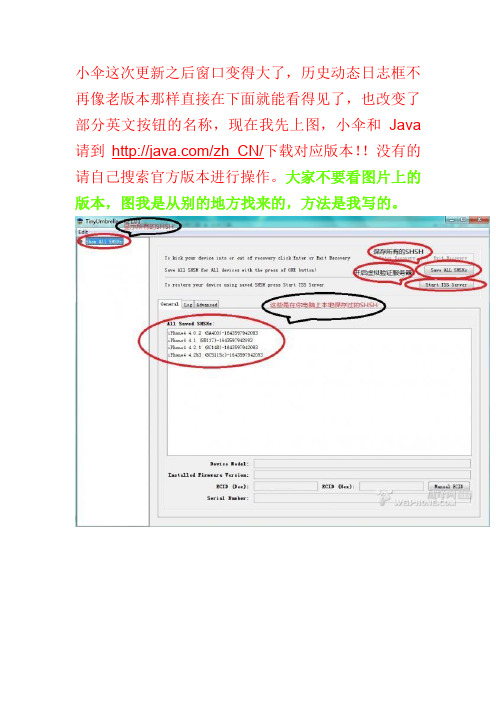
小伞这次更新之后窗口变得大了,历史动态日志框不再像老版本那样直接在下面就能看得见了,也改变了部分英文按钮的名称,现在我先上图,小伞和Java 请到/zh_CN/下载对应版本!!没有的请自己搜索官方版本进行操作。
大家不要看图片上的版本,图我是从别的地方找来的,方法是我写的。
先打开小伞,转到设置那个画面就是第三张图然后按照图上的设置打钩,至于SHSH保存在本地什么地方大家自己选,或者是默认的也行,然后保存!!连上iPhone小伞自动识别你的机器型号固件版本等,不像老版本还得自己选,识别好后就点保存所有的shsh (save all SHSH)耐心的等待吧,或者调出历史动态日志框,就是点一下log 就可以看见备份的进度了,当小伞自动查找到已有备份的SHSH在本地的时候,这时shsh就是已经备份完毕了!!!到你刚才设置的保存shsh备份的文件夹下把备份好的SHSH考到U盘里留个最保险的备份吧!!!!好了shsh备份完了,现在说一下开启小伞的虚拟验证服务器来刷固件的方法,就拿我自己的电话来举例子了,大家在图上已经看到了我备份了4个固件版本的shsh,我现在用的是ios4.2.1最新版本的固件,我就以我要降级到4.1固件来写教程,现在苹果已经关闭了对4.1固件的验证,如果这时候不开小伞而直接用iTunes来降级的话会提示1013错误,还有一个就是1013错误,我先说一下这两个错误的原因第一:1013错误,只有一个原因就是苹果关闭了验证,解决方法小伞虚拟验证。
第二:1013错误,这个错误有点蛋疼,在苹果不关闭验证的情况下用iTunes刷机遇到这个提示就说明你的电脑里有小伞工具,并且使用过它,启动小伞之后它会对你电脑里的hosts文件进行修改只要再改回默认的就好了,hosts文件在哪?怎么打开呢?它在C:\Windows\System32\drivers\etc这个文件夹里,用记事本来打开双击它,它会让你选择打开方式,找到记事本双击或确定我把原始内容发出来给你们打开之后直接把你里面的删除掉,把下面的复制进去重启iTunes就行了~~~# Copyright (c) 1993-2009 Microsoft Corp.## This is a sample HOSTS file used by Microsoft TCP/IP for Windows.## This file contains the mappings of IP addresses to host names. Each# entry should be kept on an individual line. The IP address should# be placed in the first column followed by the corresponding host name.# The IP address and the host name should be separated by at least one# space.## Additionally, comments (such as these) may be inserted on individual# lines or following the machine name denoted by a '#' symbol.## For example:## 102.54.94.97 # source server# 38.25.63.10 # x client host# localhost name resolution is handled within DNS itself.# 127.0.0.1 localhost# ::1 localhost这是在苹果没关闭验证的境况下,当关闭了验证的情况下提示这个的话,也是说明hosts被小伞改过了,但是正常境况下iTunes应该显示的是1013错误,就是在hosts文件没被修改,而是原始的状态时,显示1013说明你的hosts文件是原始的,但是这时用原始的过不了验证这一关,必须改,启动小伞就自动修改了,也就是说每次启动小伞的时候hosts都会被修改,这时修改过的就不会再出现1013错误但会出现1013 这就是下面我们要讲的,在苹果关闭了验证情况下怎么能绕开验证不过和怎么跳过1004错误来自建验证服务器刷机,降级!!!!!现在(上面说了以我的4.2.1降回4.1为蓝本)打开小伞(iTunes是关掉的而且必须关掉)查看shsh,确保有你要降到的固件的shsh,我有4.1的shsh,这时不要不管他,有就可以了,连接iPhone(iTunes 也必须是关闭的)自动启动iTunes的关掉,在回到小伞,等小伞识别出你的iPhone时点击右上角,注意看图,图上有,start TSS Server(启动虚拟验证服务器)点击之后把小伞最小化,或者放在一边,不要关闭,这时打开iTunes,把手机进入DFU模式这个都会吧?不解释了,iTunes就会找到一个要恢复的设备,这时点确定后,按住键盘上的shift键是按住,不是点一下就完了,按住后用鼠标点击iTunes上的恢复,选择你要恢复的固件文件,我要恢复4.1 我就选择4.1 之后就开始恢复了,iTunes上面显示解包,验证(验证在这时已经绕过去了)等等······大概手机上的进度条到3分之2时,这时会跳出1013错误,这时不要关闭iTunes,点1013错误上的那个确定后,iTunes 检测到一台要恢复的设备,点确定,然后直接调出你的小伞,注意不是重新打开,是刚才不是最小化了嘛?现在让它出现在你的视野里,先点一下已连接的设备,就是最左上角的connected devices 然后在回到右上角点击exit recovery (退出恢复)然后关闭小伞,这时你看看iTunes出现什么了?你的电话出现什么了?到此iPhone降级成功!!!还有就是关于保留基带升级的,刚才下面一位锋友提到了,保基带升级我发个链接得了,有锋友早就写好教程了~~/read-htm-tid-1074777.html对了已经会了的同学看看帮顶一下,写这个的原因是昨晚在等越狱的时候好多童鞋一直在问有关上面的问题·······有的说在论坛里搜索不到教程,虽然不太可能,但是为了方便一下新手,也就写了,不好之处大家都提意见和建议,谢谢了~分少的可怜,请大家给小飞点分数吧。
魔法杖移动扫描器PDS-ST470-VP用户手册说明书

Magic Wand™ Portable ScannerPDS-ST470-VPUser ManualTable of ContentsFeatures (3)1. KeyParts (3)2. Functional3. Explanation of the Status Icons (5)4. Using the Scanner (5)4.1. Charging up the Battery (5)4.2. Inserting a microSD Memory Card (not included) (6)4.3. Turn on/off the Scanner (6)4.4. HowScan (7)to4.5. How to Playback Image (9)File (10)4.6. DeleteSingleMenu (10)4.7. SetupFormat (11)ScanScanQuality (11)Color (11)ScanLanguage (11)Date/Time (11)Preview (11)InstantAuto Off (Auto Power Off) (11)Delete All (Delete All Files) (11)Format the MicroSD Memory Card (11)Information (11)Device4.8. How to Calibrate the Scanner (12)5. Connecting to Computer (12)6. Specifications (13)7. Computer System Minimum Requirements (14)8. Troubleshooting (14)Getting to know your ST470 Portable Scanner1. Key Featuresy JPEG, PDF-A4 or PDF-Letter scan-format selection. y Color or Monochromatic (mono) scan selection.y 300 (LO) /600 (MI) /1050 (HI) DPI scan quality selection.yDirectly save JPG (JPEG)/PDF files to the microSD/microSDHC card. y Support the microSD/microSDHC memory card up to 32GB. y Color display to playback the scanned images yCompatible to Windows® XP, Windows® Vista™, Windows® 7, Windows® 8, and Mac OS® 10.5 or above (direct plug-in, driver installation not required)2. Functional Parts1Power On/ Off: Press and hold this key for 3 seconds to turn power on or off.When the scanner is powered on, press this button to start scanning, pressthis button again to stop.In Setup mode, press this button to confirm changes.In Playback mode, press this button to change the magnification between 4x,8x and normal zoom.2Press this button to enter Playback mode;Press this button to return to the previous screenIn Setup mode: Press this button to exit Setup mode.3Press this button to enter Setup MenuIn Playback mode: Press this button to enter single file delete option.When zooming in under Playback mode: press this button to shift thefunctions of and between UP/DOWN and LEFT/RIGHT.4 LCD screen Display scanning status, scanned image and scanner settings.5 Press this button to select JPG (JPEG), PDF-A (PDF-A4) or PDF-L(PDF-Letter) file format. The icon of the selected mode will be displayed onthe LCD screen.In Setup mode: Press this button to move up the selection bar.In Playback mode: Press this button to preview the pervious image.When zooming in under Playback mode: press it to move to the upper/leftportion of the image.6 Press this button to select LO (300dpi), MI (600dpi) or HI (1050dpi) scanquality in DPI. The icon of the selected quality will be displayed on the LCDscreen.In Setup mode: Press this button to move down the selection bar.In Playback mode: Press this button to preview the latter image.When zooming in under Playback mode: press it to move to the lower/rightportion of the image.7 USB interface Connect to a computer with the USB cable provided to view and transfer files.To charge the built-in battery with an optional AC/DC power adapter8 Reset Press to reset the scanner (Hardware reset)9 microSD card slot The microSD/microSDHC card storage location.3. Explanation of the Status IconsItem Function Description1 FileFormat JPG/PDF-A/PDF-L2 Scan Resolution LO: 300 DPI /MI: 600 DPI / HI: 1050 DPI3 Battery Power IndicatorFully chargedLow battery. Recharge needed4 ScanColor COLOR/MONO5 FileCounter Shows the number of scanned files in the microSD card 4. Using the Scanner4.1 Charging the BatteryCharge the built-in battery before using the scanner.Charge time (while scanner is off): Approx. 2.5 hours.Two charging methods:1. By connecting to an AC/DC power adapter via the USB interface (Not included).2. By connecting to a computer via USB cable (supplied).Note:Once the battery is fully charged while the scanner is off, battery indicator will display on LCD screen for ashort time and will turn off automatically.4.2 Inserting a microSD Memory Card (not included)To operate the scanner, you must insert a microSD Card (not supplied) to record and store your pictures. To insert the microSD memory card:1. Turn OFF the scanner.2. Insert the microSD card into the microSD card slot (with metal side facing upwards). Gently press in untilthe card is clicked in and latched.4.3 Turn on/off the ScannerTurn on/off the scanner by pressing and holding.Note:If the scanner is turned on for the first time, it will enter Date & Time/Language setup mode. Once the Date & Time/ Language setting is completed, scanner will enter into standby mode.By default, Auto-off feature is set to 3 minutes. If the Auto-off feature is set at "3 Min" (refer to section 4.7), the scanner will automatically turn off if scanning action is not detected within 3 minutes.To set Date & Time/Language: 1.Press to jump to next setting option: YEAR ÆMONTH ÆDATE ÆHOUR Æ MINUTE. When setting up the value for MINUTE, press to switch to the previous setting option until it reaches the YEAR option.2. Press or to set the figure corresponding to each setting.3. Press to confirm and move to next setting.4. After completing the setting for MINUTE, it will enter Language setup screen.5. Press or to select English, Spanish or French.6.Press to confirm and enter into standby status.4.4 How to ScanNote: To scan, make sure your scanner is not connected to the computer. 1. Turn on your scanner by pressing and holding for 3 seconds.2.Place the document on a flat surface and hold down the document with one hand.3.Place the scanner on the edge of the paper approximately 5/8 to 3/4 of an inch onto the edge of the paper to ensure the whole document can be scanned. Make sure to keep the scanning area within the scanning width indicators marked on the side of the scanner.4.Hold the scanner flat against the material and then pressonce to start the scanning process.5.Slide the scanner across the document slowly, keeping your hand stable to get the best picture quality. During scanning, the scanning status icon will be displayed on the LCD screen to indicate scanning is inprogress.Once the scanner has reached the end of the document, pressagain to stop scanningNotes: yIf the scan is done too quickly or when there is any abnormal operation, “Scan Error" icon will display on the LCD screen. The image will still be saved afterthe scanning stops.y If Instant Preview feature is set to "on", scan result will shortly be displayed on the LCD screen before the scanner returns to standby mode.yWhen the memory card is full, the scanner is unable to scan more images. If you press the scan button under such situation, “Full” will flash rapidly on the File Counter of the LCD screen for 2 seconds.4.5 How to Playback Image1. Press to enter Playback mode. The last scanned image will be displayed.2.Press or to select your desired image. Pressto zoom into the image.andnavigational indicators will appear on the screen.3.Press to change the magnification between 4x, 8x and normal zoom.4. Press to view the upper portion of the image; Press to view the lower portion of the image.5.Press to shiftand navigational functions toandPress or button toview the left or right portion of the image. Press to change directions anytime.OR6.Press to return to the previous Playback screen, press it again to return to standby mode.Note: Images that exceeds 9MB file size cannot be magnified.4.6 Delete Single File1. Press to enter Playback mode. 2 Press or to select the file you want to delete. 3.Pressto enter Delete File setting.4.Press or to select Yes or No.Select “Yes” to delete the current file in the microSD card. Select “No” to return to previous Playback screen.5.Pressto confirm your selection and return to the previous Playback screen.4.7 Setup Menu1. Press to enter Setup menu2.Press or to exit Setup menu.Follow the below three steps to enter setup screen for each Menu item: 1. Press to enter setup mode.2. Press or to select the Menu item you want to set.3.Press to enter the setup screen.Menu itemsDescriptionOptionsJPG/PDF Scan Format y JPGy PDF - A (A4)y PDF - L (Letter) QualityScan Quality (DPI)y Lo (300 DPI) y Mi (600 DPI) y Hi (1050 DPI)Color Scan Colory Colory Mono Language Menu language y Englishy Spanishy French Date/Time Date and Time y Year y Monthy Datey Hour y Minute Inst. PreviewInstant previewy On y Off Auto Off Auto Power Offy Off y 3 Min Delete All Delete All Filesy No y Yes Format Format the microSD Memory Card Note: All contents on microSD card will be erased during formatingy No y YesDevice InfoDevice Information/4.8 How to Calibrate the ScannerNote: If the scanned images are too dark or too bright, you may need to calibrate your scanner by adjusting the white balance. Follow the below steps to perform calibration: 1. Wipe off any dirt on the surface of the scanning lens with the clean dry cloth provided.2. Press turn on the scanner. Place the scanner on the white area of the White Balance Calibration paper provided.3.Press and hold button. While holding the button, press the button and then release both buttons to enter into auto-calibration mode. The message “1. Calibration starts. Do not move the device!” will appear on LCD screen.4.Do not move the scanner until “2. Scan the calibration sheet!” appears on the LCD screen. Start scanning the white area of the calibration paper by sliding the scanner across the paper (slide the scanner backwards if necessary).5. “3. Calibration completed!” message will appear on the LCD screen when calibration is completed.6.Press any button to power off the scanner.5.Connecting to ComputerView your scanned files on your comptuerYou may also connect your scanner to your computer and view pictures on the computer monitor 1. Press and hold to turn on your scanner, connect your scanner to your computer to enter into USB mode. “USB” icon will display on LCD screen. 2.Your computer will recognize the scanner as a “Removable Disk”. Click “Open folder to view files” to view, import, copy, move or to delete scanned files.Note: If the Removable Device window did not launch automatically, go to your “My Computer/Computer” (PC) and find the device under Removable Storage.6.SpecificationsImage sensor Color Contact Image SensorResolution Low resolution : 300x300 dpi Medium resolution: 600x600 dpi High resolution: 1050x1050 dpiMinimum scanning speed for Letter size document Color High resolutionMono High resolutionColor Medium resolutionMono Medium resolutionColor Low resolutionMono Low resolution12.0 Seconds10.0 Seconds8.0 Seconds6.0 Seconds3.0 Seconds2.0 SecondsCapacity (Based on 1GB microSD card. Scan Letter size file, the quantity of scans varies depending on the content complexity) Color High resolutionMono High resolutionColor Medium resolutionMono Medium resolutionColor Low resolutionMono Low resolution140 Scans (Min.)150 Scans (Min.)550 Scans (Min.)600 Scans (Min.)1580 Scans (Min.)1600 Scans (Min.)Scanner photo size A4、A5、5R、4R、3R and smallerScan width Approx. 8.5”Scan length 300DPI:125"(max);600DPI:60";(max);1050DPI:50"(max)File format JPEG/PDFLCD Approx 1.5” Class* TFT LCDZoom 4x,8xDimensions (L×H×W) mm 10.5”×1.1”×1.5”Auto power off 3 MinutesUSB port USB 2.0 high speed External memory microSD/microSDHC cardStandard battery Built-in 700mAH Lithium-PolymerBattery charge time Approx. 2.5 hours7. C omputer System Minimum RequirementsOperating System Windows® XP, Windows® Vista™, Windows® 7,Windows® 8, and Mac OS® 10.5 or above (direct plug-in, driver installation not required)CPU Pentium III or aboveRAM At least 256MBInterface USBport8.TroubleshootingProblem Cause Solution Cannot turn on thescannerLow battery power Recharge the batteryPictures cannot be saved while you are scanning them 1. The microSD card has not beeninstalled2. Memory is full3. The microSD card has not beenformatted properly1. Insert a microSD card2. Transfer the pictures from the scannerto the computer to create storagespace in the memory card3. Please refer to section4.7Computer does notrecognize your scanner when connected(You cannot find your device Connection failure1. Make sure all cable connectionsare secured2. Restart the computer if necessaryunder removable disk)Blurry images1. The lens of scanner is dirty2. Contact Image Sensor aged 1. Clean the lens with soft and dry cloth 2. Recalibrate the scanner. Refer to section 4.8 Black Images/Black or white vertical lines1. Scanner sensor's protective glass is dirty2. Calibration data is off-set1. Clean the sensor’s protective glass with clean and soft dry cloth.2. Recalibrate the scanner. Refer to section 4.8Note: Model Number and Serial Number (S/N) is located on the packaging, instruction manual, on the product or inside the battery compartment. Please have this information ready before contacting tech support.FCC (Federal Communications Commission)This device complies with Part 15 of the FCC Rules. Operation is subject to the following two conditions:(1) This device may not cause harmful interference, and(2) this device must accept any interference received, including interference that may cause undesiredoperation.*Measured diagonally. Actual size is 1.48”; viewable area is 1.44”Windows® XP, Windows® Vista™, Windows® 7, Windows® 8 are registered trademarks of Microsoft Corporation. Mac OS® 10.5 is a registered trademark of Apple Inc. microSD and microSDHC logo is a trademark of SD-3C, LLC. All trademarks are the property of their respective owner.PDS-ST470-VP_Manual_13-0308AM-N470-GB-VPS-1。
s13潘多拉的备战席更新说明

s13潘多拉的备战席更新说明
S13潘多拉的备战席更新说明
1. 概述
本次更新旨在进一步提升潘多拉的备战席系统的功能和用户体验,为创作者们提供更丰富的创作工具和资源。
2. 新增功能
本次更新新增了以下功能:
•资源管理系统:创作者们可以通过备战席系统方便地管理和查找自己的资源文件,包括音频、视频、图像等。
•创作计划管理:创作者可以制定和管理自己的创作计划,设定截止日期和提醒等功能,帮助提高工作效率。
•实时协作:支持多人实时协作创作,创作者们可以邀请其他人合作编辑和评论,加快创作流程并提升创作质量。
3. 优化改进
本次更新对原有功能进行了一些优化改进,包括:
•用户界面优化:重设计创作者的用户界面,界面更加简洁直观,操作更方便快捷。
•性能优化:对系统进行了优化,提高系统的稳定性和响应速度,提供更流畅的创作体验。
•Bug修复:修复了一些已知的Bug,提升系统的稳定性和可靠性。
4. 使用指南
为了更好地使用新功能,我们提供了以下使用指南:
•资源管理系统使用指南:详细介绍了如何上传、查找和管理资源文件。
•创作计划管理使用指南:提供了如何设定创作计划和管理任务的详细步骤。
•实时协作使用指南:介绍了如何邀请他人合作创作和利用评论功能进行协作。
5. 反馈与建议
我们非常重视用户的反馈与建议,欢迎大家通过系统内的反馈渠道向我们提出宝贵意见和建议,我们会尽快回复并进行改进。
以上为S13潘多拉的备战席更新说明,希望通过本次更新能够为创作者们提供更好的创作工具和体验。
感谢大家的支持和理解!。
- 1、下载文档前请自行甄别文档内容的完整性,平台不提供额外的编辑、内容补充、找答案等附加服务。
- 2、"仅部分预览"的文档,不可在线预览部分如存在完整性等问题,可反馈申请退款(可完整预览的文档不适用该条件!)。
- 3、如文档侵犯您的权益,请联系客服反馈,我们会尽快为您处理(人工客服工作时间:9:00-18:30)。
6
新外观 & 便捷化体验
快速预览
在处大文件时激活此功能以便更流畅的观察及摆放零件
7
修复
交互式移动& 转化零件上的点以及自由点
修复复杂几何体及复杂孔洞
8
修复
零件网格重建
细化三角面片网格用以修复零件及改善零件表面光洁度
改善零件包裹功能
更快更好地处理微小壳体,锐利边缘以及纹理
更快的工作流程,仅需单击即可以快速进入烧结盒工具
摆放过程平均节约25%的时间
32
SG
透过透明零件标记内部
改良的捕捉设置用以提高手动支撑的生成效率 SG冲突警告:不再显示该提示栏
33
SG
支撑区域标记
零件上的所有支撑部分可以被轻松标记
34
支撑轮廓灵活性的改善
在机器属性中设定每种支撑类型的默认轮廓
Magics
20
版本更新
Dr. Gert Claes Product Manager Magics
版本更新:概览
基本工具:
新外观 & 便捷化体验 修复 编辑 &纹理 标记 零件摆放& 加工准备 报价 &质量控制
模块:
烧结模块 SG SG+ 树形支撑 Streamics
STL & Magics 文件图像预览
在windows文件夹内快速预览零件文件
新的默认快捷键
5
新外观 & 便捷化体验:零件列表
灵活的列显示
列的位置,宽窄以及可视与否皆可自由调节 新添‘加载零件’按钮在零件列表下方
加载零件按钮
新添修复信息到零件列表
双击零件对应的‘修复信息’即可诊断零件修复状态,再次双击则可以自 动修复零件
38
树形支撑
改善的工作流程
不需按住ctrl键即可生成树枝结构 可以同时选中多个树枝结构 多项选择(窗口选择)
39
Streamics
环形标签设计
零件上可以设置环形标签
40
Streamics
生成支撑与标签设计顺序可调 优化软件植入&工作流程
自动保存到Streamics选项 通过简化操作记录来加速运行 (可选) 改良Streamics-Magics互动日志 零件测量参数保存到Streamics
在自动摆放时利用灰度图定义优先/禁止摆放区域
20
零件摆放&加工准备
仅旋转特征摆放
新添选项特征摆放时仅旋转零件 按住Ctrl键标记多个零件的顶/底面从而达到一起旋转的效果
多零件顶/底面定义
21
零件摆放&加工准备
加工风险分析
将由于层面积不同而产生的问题易发区域可视化
22
零件摆放&加工准备
27
报价 & 质量控制:生成模版
预览图中零件尺寸可以自动调节以适应报告中单元格大小
28
报价 & 质量控制:生成模版
预览图中仅显示标记尺寸的零件
29
报价 & 质量控制:生成模版
其他模板生成的改良
新添选项显示零件及其虚拟复件的数量
更加清晰的文件名 更大的测量标签以便于阅读
30
烧结模块
纹理上的额外颜色可以被提取 出来并且再次应用到模型中
15
纹理
切换纹理可见性
一键显示/隐藏所有纹理
标记纹理
点击纹理即可标记纹理覆盖区域
16
标记
圆形&椭圆形标记并重组三角面片
在零件上标记精确的圆形或者椭圆形标记
17
标记
水平&垂直标记
一键选取所有水平/垂直方向的三角面片
18
标记
12
编辑
镜像预览
镜像操作结果立即可预览
简化三角面片过程中 “保持颜色边界”
避免颜色边界的变形
13
编辑
减少面转换为实体过程中的三角面片
转化面为实体过程中减少的三角面片的生成
14
纹理
复制& 粘贴纹理
一个零件上的纹理可以被复制粘贴到另一个零件上, 从而节约时间
纹理颜色提取
更快的重叠&交叉三角面片检测
9
修复
孔列表
简单方便地搜索探测模型上的孔
10
修复
提升自由形状孔的修复功能
精确修复形状复杂的孔,仅需单击几次
11
编辑
自支撑抽壳设计
零件抽壳而不需另加支撑
45°角捕捉切割
绘制多段线切割时,按住Alt可以固定 以45 °角绘制
45 ° 90 °
41
更多详情尽在 Materialise China(Shanghai)
42
所有标记工具都可以做到穿透标记
按住Ctrl键标记则可以穿透零件进行标记
按住Ctrl键并滚动滚轮即可改变笔刷标记的尺寸
简单改变笔刷标记尺寸
45° 角捕捉多边形标记并重建网格
在多边形标记时按住 Alt键即可以45°或90°描绘多段线
45 °
90 °
19
零件摆放&加工准备
个性化定制的自动摆放
新外观 & 便捷化体验
现代化的外观
更加清晰的工具布局与功能浏览 创建自定义的功能区,工具条,目录菜单等等
用户友好的个性化设置
3
新外观 & 便捷化体验
快捷搜索
简单搜寻并加载magics工具按钮
通过拖拽更改机器平台顺序
按照您喜欢的方式来安排机器平台窗口
4
新外观 & 便捷化体验
零件默认沿Z方向摆放
单击Home或者对应按钮将零件沿默认Z轴方向摆放
在设计者视图组合
23
报价 & 质量控制
查看(支撑)体积以及零件材料成本
零件的体积,其支撑的体积以及材料成本皆可以显示 在计算用料时激光的厚度也被计入考虑范围
更加精准的支撑体积估算
24
报价 & 质量控制
在3D pdf文件中查看错误
限制摆放时间
新建选项:输入摆放时间,超过此时间 则摆放过程停止
从当前设置开始
重新摆放时不需要再将平台上的零件移 出
多平台摆放
当所有零件不能同时摆放在同一台机器 上时,可以选择摆放在其他已经打开的 机器平台上或者当前机器的多个相同平 台上
31
烧结模块
两个烧结盒按钮分别对应自由形状烧结盒&长方体烧结盒
在SG支撑列表中自由更换支撑轮廓 从其他机器平台中复制支撑轮廓信息
35
SG+
改良的圆锥支撑自动摆放
最低线支撑 在用户自定义的尺寸范围内自动调节圆锥支撑尺寸
36
新界面---修改支撑投影区域
修改支撑投影区域再也不用切换小窗口啦!
37
支撑Z轴偏移支持负值
可以避免在直立厚壁上生成倾斜的块状支撑时产生的问题
反向三角面片以及坏边现在可以在输出的3D pdf文件中查看
25
报价 & 质量控制
清晰图标表示公差范围与否
新加勾/叉 图标以便于在黑白图纸上清楚显示信息
测量结果仅显示OK 或者 NOT OK
测量结果须满足相对公差以及绝对公差以获得OK的公差检测结果
26
报价 & 质量控制
在同一图像中显示零件所有测量尺寸