H009 AHKC-BS系列20A-500A闭口式霍尔电流传感器参数说明书V1.0
HDBS蓄电池内阻测试仪说明书
安全规则及注意事项感谢您购买了本公司蓄电池内阻测试仪,在你初次使用该仪器前,为避免发生可能的触电或人身伤害,请一定:详细阅读并严格遵守本手册所列出的安全规则及注意事项。
✧请注意+/-极性,请勿反向插入。
✧测量电池电压不要超过本仪表的上量限。
✧仪表显示电池电压低符号“”,应及时充电,否则会引起测量误差。
✧长时间不使用时,每三个月充满电一次以保证电池健康。
✧本仪表根据IEC61010安全规格进行设计、生产、检验。
✧测量时,移动电话等高频信号发生器请勿在仪表旁使用,以免引起误差。
✧注意本仪表机身的标贴文字及符号。
✧使用前应确认仪表及附件完好,才能使用。
✧请勿于高温潮湿,有结露的场所及日光直射下长时间放置和存放仪表。
✧注意本仪表所规定的测量范围及使用环境。
✧使用、拆卸、校准、维修本仪表,必须由有授权资格的人员操作。
✧由于本仪表原因,继续使用会带来危险时,应立即停止使用,并马上封存,由有授权资格的机构处理。
✧仪表及手册中的“行安全操作。
✧任何情况下,使用本仪表应特别注意安全。
二、简介HDBS蓄电池电池内阻测试仪简称:电池内阻测试仪,是用于测量铅蓄电池、锂电池等充电电池的内阻、电压与温度,以判断电池健康状态的测量仪器,同时可以作为测量电解电容ESR参数的仪表(仅供参考)。
本仪表使用交流4端子测试法测量电池内阻,可不受测试线、端子与电池电极之间接触电阻影响测量正确的测量值。
同时还具有数据存储、数据查阅、报警、自动关机等功能。
整机高档美观,量程宽广,分辨率高,操作便捷,携带方便,准确、可靠、性能稳定,抗干扰能力强。
是电池生产、电池安装、设备生产、设备维修等场景必不可少的仪器。
HDBS电池内阻测试仪由微处理器控制,内部16位ADC可准确检测电池内阻、电压与温度。
其特点在不停止UPS系统的状态下进行测量,使用交流低电阻测量和降噪技术,不需要停止被测设备的正常工作,在运转状态下进行测量,极大的缩短了测试时间。
同时带有数据存储、柱状图显示、数据上传电脑、手机平板等智能设备蓝牙连接进行无线测量、查阅数据等功能。
CTB系列 高精度电流探头说明书
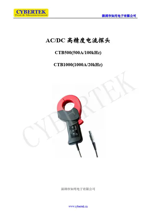
深圳市知用电子有限公司AC/DC 高精度电流探头CTB500(500A/100kHz) CTB1000(1000A/20kHz)深圳市知用电子有限公司CY BE R TE K前 言首先,感谢您购买该产品。
为了你安全正确地使用本产品,请先仔细阅读说明书。
这份产品使用说明书是关于该产品的功能、使用方法、操作注意事项等方面的介绍。
说明书中,注释将用以下的符号进行区分。
为安全使用本机器必须严格遵守以下安全注意事项。
如果不按照该说明书使用的话,有可能会损害机器的保护功能。
此外,因违反注意事项进行操作所产生的问题,本公司概不负责。
◆请避免接触裸导体。
否则可能会导致短路事故或触电。
◆ 请在相对于电路电压具有适当绝缘性的绝缘电线位置上进行测量。
◆ 机器潮湿,或用湿手测定的话,会发生触电事故,请注意。
◆ 最大测量电流因频率而异,作为降低额定值的措施,限制可连续测量的电流。
请勿测量超出额定值降低幅度的电流。
如果测量,则可能会因为传感器发热而导致故障,火灾与烫伤等。
在错误操作的情况下,用户有受伤的威胁,为避免此类危险,记载了相关的注意事项。
该符号表示对人体和机器有危害,必须参照说明书操作。
记载着使用该机器时的重要说明。
错误操作时,用户有受轻伤和物质损害的可能,为避免此类情况,记载的注意事项。
BE R TE K◆ 请勿使钳口顶端部分夹入异物,否则可能会导致传感器特性降低或者开关动作不良。
◆ 在切断连接仪器电源的情况下,请勿向本设备输入电流,否则可能会导致本仪器损坏。
◆ 为了不损坏电线的外皮,请不要踩踏或者夹住电线。
◆ 请勿在打开钳口部分的状态下触摸芯体部分,如果芯体部分静电放电,则可能会损坏本设备。
◆ 不使用时请关闭钳口,如果长期打开,钳口接触面会附着灰尘,可能会造成测量误差。
◆ 要拔出输出连接器时,请务必在解除锁定后拔出,如果强行拔拉电线,则会造成连接器损坏。
◆ 在0℃以下的环境下使用,电缆会变硬。
如果在这种状态下弯曲或者拉拽电缆,则可能会导致电缆外皮损坏或者断线。
自动检测技术及应用ppt课件第8章 霍尔传感器
若控制电流值固定,则: VH=KBB
传感器及检测技术
KB——磁场灵敏度,通常以额定电流为标准。磁场灵敏 度等于霍耳元件通以额定电流时每单位磁感应强度对应 的霍耳电势值。常用于磁场测量等情况。 若磁场值固定,则:
VH=KI I
KI——电流灵敏度,电流灵敏度等于霍耳元件在单位磁 感应强度下电流对应的霍耳电势值。
传感器及检测技术
VH/mV 80 60
霍耳电势随负载电阻值而改变的情况
λ=R3/R2
λ=∞ λ=7.0 λ=3.0 λ=1.5
理论值 实际值
40 20
I
R3 VH
0 0.2 0.4 0.6 B/T 0.8 1.0
霍耳电势的负载特性
传感器及检测技术
6、温度特性:指霍耳电势或灵敏度的温度特性,以及 输入阻抗和输出阻抗的温度特性。它们可归结为霍耳 系数和电阻率(或电导率)与温度的关系。 双重影响:元件电阻,采用恒流供电;载流子迁移率, 影响灵敏度。二者相反。
VOUT/V 12
ON
OFF
0
BRP BH BOP B
霍耳开关集成传感器的工作特性曲线
霍耳开关集成传感器的技术参数: 工作电压 、磁感应强度、输出截止电压、 输出导通电流、工作温度、工作点。
磁场与传感器输出电平 的关系。当外加磁感强 度高于BOP时,输出电 平由高变低,传感器处 于开状态。当外加磁感 强度低于BRP时,输出 电平由低变高,传感器 处于关状态。
传感器及检测技术
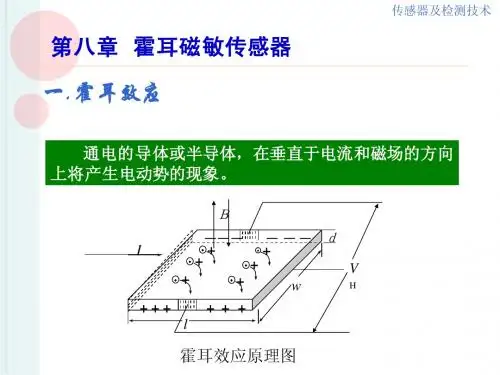
三.霍耳磁敏传感器(霍耳器件)
电流极
D
霍耳电极
B
s
A
5.4 2.7
d
霍尔电流传感器AHKC系列产品说明
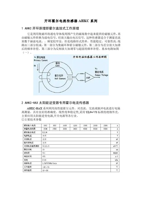
开环霍尔电流传感器AHKC系列
1AHKC开环原理即霍尔直放式工作原理
它是利用集磁环将通电导体线周围产生的磁场集中起来提供给磁敏元件,再由磁敏元件转换为弱电信号,经放大输出电压信号,这种传感器适合于测量直流到数千赫兹电流,,频宽较窄没,但是线路形式简单,性能稳定,可靠性高。
线路由三部分组成,第一部分为集磁环和霍尔磁敏元件,第二部分为差分放大加滞后的频率补偿,第三部分为反相放大加调零与超前的频率补偿。
基本电路如图(一)。
2AHKC-HAX太阳能逆变器专用霍尔电流传感器
AHKC-HAX系列利用高性能霍尔元件,对直流、交流或脉冲电流进行电隔离测量,具有良好的准确度、线性度和稳定性,采用UL94-V0标准的绝缘外壳。
主要应用太阳能逆变电源,开关电源等各行业。
①主要技术参数
②结构参数
③输出方式:5045-04AG/4Pin插针
+-M G
+15V-15V输出端(仪表输入正极)电源COM与仪表输入负极
3AHKC-K改造专用电流传感器
①主要参数
②结构参数
4AHKC-EKAA系列霍尔电流传感器
AHKC-EKAA系列霍尔可拆卸电流传感器是应用霍尔效应原理开发的新一代电流传感器,能在电隔离条件下测量直流、交流、脉冲以及各种不规则波形的电流。
①主要参数
②结构参数
③输出方式
输出为3.5-4Pin连接器
2个G端子为内部PCB板相通
+G M G
+24V电源COM输出端电源COM。
霍尔传感器样本手册——安科瑞 华楠
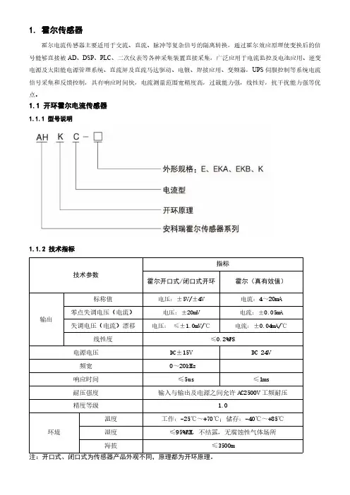
1.霍尔传感器霍尔电流传感器主要适用于交流、直流、脉冲等复杂信号的隔离转换,通过霍尔效应原理使变换后的信号能够直接被AD 、DSP 、PLC 、二次仪表等各种采集装置直接采集,广泛应用于电流监控及电池应用、逆变电源及太阳能电源管理系统、直流屏及直流马达驱动、电镀、焊接应用、变频器,UPS 伺服控制等系统电流信号采集和反馈控制,具有响应时间快,电流测量范围宽精度高,过载能力强,线性好,抗干扰能力强等优点。
1.1开环霍尔电流传感器1.1.1型号说明1.1.2技术指标技术参数指标霍尔开口式/闭口式开环霍尔(真有效值)输出标称值电压:±5V/±4V 电流:4~20mA 零点失调电压(电流)电压:±20mV电流:±0.05mA失调电压(电流)漂移电压:≤±1.0mV/℃电流:±0.04mA/℃线性度≤0.2%FS电源电压DC ±15V DC 24V频宽0~20kHz 响应时间≤5us≤1ms耐压强度输入与输出及电源之间允许AC2500V 工频耐压精度等级1.0环境温度工作:-25℃~+70℃;储存:-40℃~+85℃湿度≤95%RH,不结露,无腐蚀性气体场所海拔≤3500m注:开口式、闭口式为传感器产品外观不同,原理都为开环原理。
1.1.3开口式开环霍尔电流传感器1.1.3.1规格尺寸(单位:mm)图1图21.1.3.2规格参数对照表型号额定电流供电电源额定输出测量孔径(mm)准确度AHKC-EKA 0~(50-500)A ±15V 5V /4V φ201级AHKC-EKAADC 0~(50-500)A12V/24V4~20mAφ201级尺寸规格外形尺寸穿孔尺寸安装尺寸图形W H D a e ΦM N AHKC-EKA 606416//2047/图1AHKC-EKAA 606416//2047/图1AHKC-EKDA 606416//2047/图1AHKC-EKB 10010224//4080/图1AHKC-EKBA 10010224//4080/图1AHKC-EKBDA 10010224//4080/图1AHKC-EKC 11511027//6095.5/图1AHKC-EKCA 11511027//6095.5/图1AHKC-EKCDA 11511027//6095.5/图1AHKC-K 12763256416//30图2AHKC-KAA 12763256416//30图2AHKC-KDA 12763256416//30图2AHKC-H 14979258232//46图2AHKC-KA 17695.52910436//60图2AHKC-HB 204111.52913252//48×2图2AHKC-HBAA 204111.52913252//48×2图2AHKC-HBDA204111.52913252//48×2图2AHKC-EKDA AC 0~(50-500)A 12V/24V 4~20mA φ201级AHKC-EKB 0~(200-1000)A±15V 5V /4V φ401级AHKC-EKBADC 0~(200-1000)A 12V/24V4~20mAφ401级AHKC-EKBDA AC 0~(200~1000)A 12V/24V 4~20mA φ401级AHKC-EKC 0~(500-1500)A±15V 5V /4V φ551级AHKC-EKCADC 0~(500-1500)A 12V/24V4~20mAφ551级AHKC-EKCDA AC 0~(500-1500)A 12V/24V 4~20mA φ551级AHKC-K 0~(400-2000)A±15V 5V /4V 64×161级AHKC-KAA DC 0~(400-2000)A 12V/24V4~20mA64×161级AHKC-KDAAC 0~(400-2000)A12V/24V 4~20mA 64×161级AHKC-H 0~(500-3000)A ±15V 5V /4V 82×321级AHKC-KA 0~(500-5000)A±15V 5V /4V 104×361级AHKC-HB0~(2000-20000)A±15V5V /4V132×521级AHKC-HBAA DC 0~(2000-20000)A12V/24V 4~20mA 132×521级AHKC-HBDA AC 0~(2000-20000)A12V/24V 4~20mA 132×521级注:额定电流未标注表示输入电流交直流均可测量,订货时请注明。
霍尔电流传感器原理图
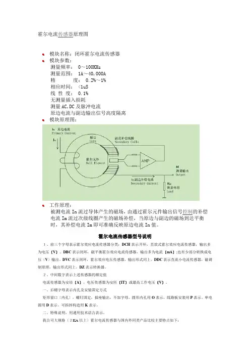
霍尔电流传感器原理图模块名称:闭环霍尔电流传感器模块参数:测量频率: 0~100KHz测量范围: 1A~40,000A精度: 0.2%~1%相应时间: <1uS线性度: 0.1%无测量插入损耗测量AC,DC及脉冲电流原边电流与副边输出信号高度隔离模块原理图:工作原理:被测电流In流过导体产生的磁场,由通过霍尔元件输出信号控制的补偿电流Im流过次级线圈产生的磁场补偿,当原边与副边的磁场到达平衡时,其补偿电流Im即可准确反映原边电流In值。
霍尔电流传感器型号说明1、前三个字母表示霍尔效应电流传感器分类:DCH表示开环,直放式霍尔效应电流传感器,输出多为电压〔V〕。
DBC表示闭环,磁平衡霍尔效应电流传感器,输出多为电流〔mA〕;也有少部分转换成电压〔V〕输出。
DVC表示闭环,霍尔效应电压传感器,输出形式同上。
DDC表示直流小电流传感器,磁调制原理,输出形式同上。
DZ表示转换器。
2、中间数字表示上述传感器的额定值电流传感器为安培〔A〕,电压传感器为安匝〔IT〕或最高工作电压〔V〕。
一、后辍字母表示内孔及安装固定方式矩形窗口〔内孔〕,螺钉固定,插座输出,不加字母。
圆形内孔用O表示,线路板安装用P表示。
单电源用D表示。
可拆卸构造用K表示。
二、特殊说明,用通用技术语言表示。
我公司大规格〔2KA以上〕霍尔电流传感器与国内外同类产品比较主要特点如下:1、磁路采用去剩磁技术措施,磁失调<0.05%。
一般产品磁失调达百分级,已接触到国外公司产品也不例外。
部分产品由于过载产生剩磁,可使产品报废。
2、本产品对外磁场干扰,采用外磁场抵消法;双路磁路使干扰磁场相对抵消。
而信号磁场设计在强磁场状态,外磁场比信号磁场弱,影响可忽略。
3、电路采用双恒温措施,减少温漂,进步稳定度。
大型电流传感器采用多霍尔对称部局、强信号磁场,大大减轻了霍尔元件的不等位影响。
上述技术措施,本公司大型电流传感具有如下特点:〔1〕高准确度、高稳定性、高可靠性,可适用任何工作现场。
蓄电池内阻分析仪说明书
免责声明
信息, 对于用户由于未遵守下列条款而造成的 人身安全和财产损失, 本公司仪器将不承担任 何责任。
仪器接地 不可在爆炸性气体 环境使用仪器
为防止电击危险,请连接好电源地线。 不可在易燃易爆气体、 蒸汽或多灰尘的环境下 使用仪器。 在此类环境使用任何电子设备, 都 是对人身安全的冒险。 非专业维护人员不可打开仪器外壳, 以试图维 修仪器。 仪器在关机后一段时间内仍存在未释 放干净的电荷,这可能对人身造成电击危险。
8.SCPI 命令参考................................................................................ 26
8.1 8.2 8.3 8.4 8.5 8.6 8.7 8.8 8.9 8.10 8.11 8.12 8.13 命令串解析 ............................................................................................................................. 26 命令和参数 ............................................................................................................................. 27 命令参考 ................................................................................................................................. 29 DISPLAY 显示子系统 ............................................................................................................... 29 FUNCTION 子系统 .................................................................................................................... 30 COMPARATOR 子系统 .............................................................................................................. 31 TRIGGER 子系统....................................................................................................................... 33 FETCH? 子系统 ........................................................................................................................ 34 CORRECTION 子系统 ................................................................................................................. 34 SYSTEM 子系统 ........................................................................................................................ 34 IDN? 子系统............................................................................................................................ 35 ERROR 子系统 ......................................................................................................................... 35 SAV 子系统 ............................................................................................................................. 35
直流漏电流传感器-霍尔电流传感器 产品说明书
直流漏电流传感器直流漏电流传感器是一种利用磁通门原理将被测直流电流转换成与该电流成比例输出的直流电流或电压信号的测量模块,原副边之间高度绝缘。
通常输出标准的直流DC4-20mA,DC0-5V,DC0-10V等信号,此标准信号可以被多种采集设备采集,如PLC,RTU,DAS卡等,用于多种电流监控的场合。
符合标准:霍尔电流传感器产品符合JB/T7490-2007《霍尔电流互感器行业标准》功能用途(应用场合)):功能用途(应用场合近年来国家对各行业的电气火灾的强制规定,使得直流供电系统得到了很大发展空间,直流供电系统广泛应用于各种发电厂,通信基站,消防领域中的断路器控制电源,应急电源等,在直流系统中直流漏电流传感器是不可或缺的一个重要元器件,对于设备的直流泄漏电流进行检测,广泛应用于直流输电、蓄电检测、直流屏、电源、大型医疗卫生设备、光伏、风力发电、通信基站等行业货设备中,第一时间对设备的漏电情况进行反馈,后端的漏电保护等原件会在第一时间采取相关措施,避免事故发生,安全使用、生产作业。
技术指标直流漏电流传感器辅助电源±15V(±13V~±17V)响应时间≤300mS失调电压40mV准确级1级工作温度-25~70℃温度系数400ppm输出负载≥10k输入过载能力输入量程最大值10倍/3S;输入量程最大值3倍/2h工作电流≤15mA耐压 2.5kV执行标准JB/T11205-2011直流漏电流传感器外观结构及选型说明:霍尔(闭环)电流传感器根据外形分为三种类型:AHLC-LTA、AHLC-EA、AHLC-EB,外观如下:直流漏电流传感器安装方式环境要求:1、工作场所:无雨雪直接侵袭、无腐蚀性气体和剧烈震动的场所;2、工作环境温度:-25℃~+70℃;贮存环境温度:-40℃~+80℃;3、工作环境相对湿度:<95%RH,不结露;4、海拔高度:≤2000m;5、采用螺丝固定安装;6、接线端子采用绿色可插拔端子范例型号:AHLC-LTA辅助电源:DC ±15V输入:200mA输出:5V作者简介:戴金花,女,本科,江苏安科瑞电器制造有限公司,主要研究方向为电量传感器设计,Email:2880157871@ 手机:188********QQ:2880157871分类AHLC-LTAAHLC-EA AHLC-EB输入信号1010~~1000mA 1010~~1000mA 1010~~1000mA 输出信号5V 5V 5V。
解析霍尔电流传感器
解析霍尔电流传感器当原边导线经过电流的输出信号是副边电流is,它与输入信号(原边电流ip)成正比,is一般很小,只有10~400ma。
如果输出电流经过测量电阻rm,则可以得到一个与原边电流成正比的大小为几伏的电压输出信号。
2、传感器供电电压vava指电流传感器的供电电压,它必须在传感器所规定的范围内。
超过此范围,传感器不能正常工作或可靠性降低,另外,传感器的供电电压va又分为正极供电电压va+和负极供电电压va-。
要注意单相供电的传感器,其供电电压vamin 是双相供电电压vamin的2倍,所以其测量范围要相供高于双电的传感器。
3、测量范围ipmax测量范围指电流传感器可测量的最大电流值,测量范围一般高于标准额定值ipn。
三、电流传感器主要特性参数1、标准额定值ipn和额定输出电流isnipn指电流传感器所能测试的标准额定值,用有效值表示(a.r.m.s),ipn的大小与传感器产品的型号有关。
isn指电流传感器额定输出电流,一般为10~400ma,当然根据某些型号具体可能会有所不同。
2、偏移电流iso偏移电流也叫残余电流或剩余电流,它主要是由霍尔元件或电子电路中运算放大器工作状态不稳造成的。
电流传感器在生产时,在25℃,ip=0时的情况下,偏移电流已调至最小,但传感器在离开生产线时,都会产生一定大小的偏移电流。
产品技术文档中提到的精度已考虑了偏移电流增加的影响。
3、线性度线性度决定了传感器输出信号(副边电流is)与输入信号(原边电流ip)在测量范围内成正比的程度,南京中旭电子科技有限公司的电流传感器线性度要优于0.5%。
4、温度漂移偏移电流iso是在25℃时计算出来的,当霍尔电极周边环境温度变化时,iso会产生变化。
因此,考虑偏移电流iso的最大变化是很重要的,其中,iot是指电流传感器性能表中的温度漂移值。
5、过载电流传感器的过载能力是指发生电流过载时,在测量范围之外,原边电流仍会增加,而且过载电流的持续时间可能很短,而过载值有可能超过传感器的允许值,过载电流值传感器一般测量不出来,但不会对传感器造成损坏。
NK技术-电流传感器、电流开关和地闸系列产品说明书
C O N T E N T SATR 0, 1 & 2 SeriesTrue RMSAC Current Transducers2–3AT 0, 1 & 2 SeriesAC Current Transducers4–5ATR 3 & 4 SeriesHigh Current Transducers6–7DT 1, 2, 3 & 4 SeriesDC Current Transducers8–9AS1 Series Current Operated Switches 10–11ASM Series Self CalibratingCurrent Switches12–13AS3 Series Current Operated Switches 14–15AS3M Series Multi-poleCurrent Operated Switches16AG 1, 2 & 3 SeriesGround Fault Sensors17–19DS3 Series DC Current Switches 20–21Accessories s PBR SeriesPowerBASE™ Relays 22s Power Supply23s DIN Universal Rail Clips 23s Instrument Tags23For expert technical help, contact your localAuthorized Representative or Authorized Distributork now your power . . .because with knowledge comes control.PAGEContact us for:s Product Guide s Application Guides Power Transducers, CTs and PTs s Current Transducers and Transmitters s Current Switches sCurrent Fault SensorsDo you have other needs?Industrial Current SensorsA pplicationsVFD Controlled LoadsVFD output indicates how the motor and attached load are operating.SCR Controlled LoadsAccurate measurement of phase angle fired or burst fired (time proportioned)SCRs. Current measurement gives faster response than temperature measurement.Switching Power Supplies and Electronic BallastsTrue RMS sensing is the most accurate way to measure power supply or ballastF eaturessTrue RMS OutputTrue RMS technology is accurate on distorted waveforms like VFD or SCR outputs.s Jumper Selectable Ranges — Reduces inventory.— Eliminates zero and span pots.s Isolation— Output is magnetically isolated from the input for safety.— Eliminates insertion loss (voltage drop).s UL, CUL and CE Approval Accepted worldwide.L I N ETrue RMS AC Current TransducersSelecting the right transducer:VFD and SCR output waveforms are rough approximations of a sine wave.There are numerous spikes and dips in each cycle. ATR transducers use a mathematical algorithm called “True RMS,” which integrates the actual waveform over time. The output is the amperage component of the true power (heating value) of the AC currentwaveform. True RMS is the only way toaccurately measure distorted ACwaveforms. Select ATR transducers for nonlinear loads or in “noisy” power environments.The current waveform of a typical linear load is a pure sine wave. AT transducers measure the peaks of these sine waves,then calculate the average amperage.This works well on constant speed linear loads in a “clean” powerenvironment. Select AT transducers for strictly linear loads on “clean” power.‘ATR’ transducers from NK Technologies combine a currenttransformer and a True RMS signal conditioner into a single package.The ATR Series provides True RMS output on distorted waveforms found on VFD or SCR outputs and on linear loads in “noisy” power environments. Available in a solid or split core case.Instrument Tags allow users to individually identify each NK Technologies sensor in their system. IT Tags are permanent and non conductive. Traditional stamped stainless steel tags present a safety hazard and are not recommended for electrical sensors. Please provide a list of tag numbers with your Purchase Order.Dimensions 0.5" x 1.125"Characters2 lines of 18 characters (8 point).Spaces and dashes count as characters.Power SupplyS pecificationsInput 85–264VAC, 47-400Hz DC Output 24VDC, 25W (1.05A)DC Regulation +/–0.2% (0.048VDC)Dimensions 5.1" x 3.85" x 1.5", 1.5 lb.(13 x 9.8 x 3.8 cm, 700 gm)Environmental 14 to 140°F (–10 to +60°C), 20–90% RH PS series switching power supplies provide highlyregulated 24VDC for NK Technologiestransmitters and switches.Sensor and DIN rail not included in DIN-2 kit.ATR SeriesAccessoriesA pplicationsTotal Loop Impedance (Ohms)Notes:s Pressure plate screw terminals.s 12–22 AWG solid or stranded.s Field adjustable setpoint.Example: DS1-SDT-24UDS current switch, low range with SPDT relay contacts and 24VAC/DC power supply.O rdering InformationPower Supply Isolated Relay Output Isolated Solid State Output 34–20, 10–50 and 15–100A, Jumper Select C Custom (consult factory)SDT SPDT Relay (Form C)NOU Solid State N.O. AC/DC DS24U +24VAC/DC0%utput Operation‘AT’ Current Transducers from NK Technologies combine a current transformer and signal conditioner into a singlepackage. The AT Series has jumper selected currentinput ranges and industry standard4–20mA, 0–5VDC or 0-10VDC outputs. The AT Series is designed for application on ‘linear’ or sinusoidal AC loads.Available in a split core case or two types of solid core cases.A pplicationsAutomation SystemsAnalog current reading for remote monitoring and software alarms.Data LoggersSelf-powered transducer does not drain data logger batteries.Panel MetersSimple connection displays power consumption.L I N EAC Current TransducersAT SeriesAT Current TransducersF eaturessAccurateFactory matched and calibrated single piece transducer is more accurate than traditional two-piece field installed solutions.s Average Responding“Average Responding” algorithm gives a RMS output on pure sine waves. Perfect for constant speed (linear) loads.s Jumper Selectable Ranges — Reduces inventory.— Eliminates zero and span pots.s Isolation— Output is magnetically isolated from the input for safety.— Eliminates insertion loss (voltage drop).s UL, CUL and CE Approval Accepted worldwide.I nput RangesMAXIMUM Model Range Continuous 6 Sec. 1 Sec. AT02A80A 60A 100A 5A100A 124A 250A AT110A80A 125A 250A 20A 110A 150A 300A 50A175A 215A 400A AT2100A200A 300A 600A 150A 300A 450A 800A 200A400A500A 1,000A1m Ω Recommended 100k Ω AcceptableC AC Current TransducersA pplicationsElectric Heating ElementsInstant indication of heater status.Power SuppliesSignals over-current before equipment fails.Machine OperationInstant status of motors, lamps and other loads.Telecom SitesMonitors battery output.‘DS3’ Current Switches from NK Technologies Hall effect sensor, signal conditioner and a limit alarm into a single package. The DS3 Series has three jumper selected current input ranges and frequency response from DC to 400Hz. Available in a top terminal solid core case with either a relay output or a universal solid state output.F eaturessCompact, One-piece DesignFits in crowded motor starters, power supplies and control panels.s Input IsolationMuch safer than shunt/relay combinations.s Output InstallationIsolated output greatly simplifies wiring.s ToughDesigned to handle harsh industrial environments.s Adaptive Hysteresis— Hysteresis is 5% of setpoint.— Allows closer control than fixed hysteresis.s ReliableSolid state design.s Built-in Mounting BracketSolid, secure mounting that inspectors want to see.DC Current SwitchesDS3 Seriess –FT Case : 0.75" (19mm) dia.s –SP Case: 0.85" (21.5mm) sq.CaseUL 94V-0 flammability ratedEnvironmental –4 to 122°F (–20 to 50°C), 0–95% RH, non-condensing ListingsUL 508 Industrial Control Equipment (USA & Canada), CErdering InformationExample: AT1-005-000-SPAC current transducer, 10/20/50A range, self-powered with a 0–5VDC output in a split core case.Ranges 02 & 5A 110, 20, 50A 2100, 150, 200A 4204–20mA 0050-5VDC 0100-10VDC 24L 24VDC Loop-powered (4–20mA output ONLY)000 Self-powered (0–5/0–10VDC output ONLY)ATFF Fixed Core,Front Term.FT Fixed Core,Top Term.SP Split CoreP L o o p P o w e r (V D C )Normally Energized Models (–FS Option)Protection from faultsand loss ofcontrol power.No Power No Fault Fault N.C. Normally Closed Closed OPEN Closed N.O. Normally OpenOpenCLOSEDOpenNormally Deenergized Models (–NF Option)Protection from faultsonly when control poweris applied.No Power No Fault Fault N.C. Normally Closed Closed CLOSED Open N.O. Normally OpenOpenOPENClosedLatching (–LA Option)Latching models initially power up in the Reset position.If there is a fault or the test button is pressed, the output switches and is latched. The output will remain latched after the fault is cleared, even if control power is removed. To reset the output, apply a momentary contact across the “Reset” terminals (6–7).O utput TableControl Power Applied Control Power Applied S pecificationsSetpoint Ranges “Single-Set” Models Factory adjusted and sealed(field adjustment possible)s AG1: 5–100mA, specify when ordering s AG2: 80–950mA, specify when orderings “Tri-Set” Models 5, 10 & 30mA jumper select Output Isolated dry contact (solid state or relay,see Ordering Information)Output Ratings Solid State AC Switch: 1A @ 240VAC s Solid State DC Switch: 0.15A 30VDC s Relay: 0.5A @ 125VAC, 2A @VDCOff State Leakage NoneResponse Times 200mS @ 5% above setpoint s 60mS @ 50% above setpoint s 15mS @ 500% above setpointIsolation Voltage Up to 1,250VAC (monitored circuit)Frequency Range 50–400Hz (monitored circuit)Sensing Aperture 0.75" (19mm) dia., up to 4" (100mm) dia.available, consult factory.Power Supplys 120, 200, 208, 220, 240VAC, 50-400Hz, operates from 55–110% of nominal voltage s 24VAC & 24VDC, operates +/–10%s Green LED = power (all models)Case UL 94V-O Flammability rated Environmental 5 to 158°F (–15 to 70°C),0-95% RH, non-condensing‘AT/ATR 3 & 4’ transducers from NK Technologies combine a high capacity current transformer and a signal conditioner into a single package. The AT version is Average Responding for use on linear(sinusoidal) loads. The ATR version is True RMS for use on distorted waveforms found in VFD or SCR outputs.Available in a solid or split core case.A pplicationsLarge PumpsDetect dry run electronically.GenerationMeasure the output of generators.Electric Heating Elements — Monitors heater load.— Faster response than temperature sensors.F eaturessLarge ApertureAccommodates large conductors or wire bundles.sSelect the Right OutputTrue RMS technology is accurate on distorted waveforms like VFD or SCR outputs.Average Responding—for linear,sinusoidal waveformss Three Jumper Selectable Ranges — Reduces inventory.— Eliminates zero and span pots.IsolationMagnetic isolation protects installers and systems.Easy InstallationSingle piece with integral mounting brackets makes for a simple, solid installation.UL, CUL and CE Approval Accepted worldwide.Selecting the right transducer:The current waveform of a typical linear load is a pure sine wave. AT transducers measure the peaks of these sine waves,then calculate the average amperage.This works well on constant speed linear loads in a “clean” powerenvironment. Select AT transducers for strictly linear loads on “clean” power.VFD and SCR output waveforms are rough approximations of a sine wave.There are numerous spikes and dips in each cycle. ATR Transducers use a mathematical algorithm called “True RMS,” which integrates the actual waveform over time. The output is the amperage component of the true power (heating value) of the AC currentwaveform. True RMS is the only way to accurately measure distorted ACwaveforms. Select ATR transducers for nonlinear loads on “noisy” power.LI NEAT/ATR 3 & 4 SeriesShown withsolid core case.Example: AG1-NOAC-120-005-FSGround fault sensor with normally open solid state output, 120VAC power supply, 5mA setpoint, fail safe version.24U 24VAC/DC 120120VAC 200200VAC208208VAC 240240VAC NCAC Normally Closed 1A @ 240VACNOAC Normally Open 1 A @ 240VACNCDC Normally Closed 0.15A @ 30VDC NODC Normally Open 0.15A @ 30VDCNCR1Normally Closed Relay,0.5A @ 125VAC, 2A @ 30VDC NOR1 Normally Open Relay,0.5A @ 125VAC, 2A @ 30VDCCR1Form C Relay (SPDT) 0.5A @ 125VAC, 2A @ 30VDC(available only with LA Latching Option)TR3Tri-Set Models 005Factory AdjustedSetpoint in mA 950AGO rdering Information15–100mA, Adjustable 280–950mA, Adjustable35, 10 & 30mA, Jumper SelectFS Normally Energized NF Normally Deenergized LA Latching (available only with CR1 Output Option)k now your power . . .because with knowledge comes control.Specifications Output Signal 4–20mA, Loop-powered Output Limit 23mAAccuracy1.0% FS accuracy, True RMS Measurement True RMS or Average Responding (see Ordering Information)Response Time 500mS (to 90% of step change)Frequency Range s ATR: 10–400HzsAT: 50–60Hz, SinusoidalPower Supply 24VDC Nominal; 40VDC Maximum Isolation Voltage 600VACInput Ranges s AT/ATR3: 375, 500, 750A s AT/ATR4: 1000, 1333, 2000A Sensing Aperture 3.0" (76mm) dia.CaseUL 94 Flammability rated Environmental –4 to 122°F (–20 to 50°C),0–95% RH, non-condensingListingsUL 508 Industrial Control Equipment s Observe polarity.Example: ATR4-420-24L-FLTrue RMS AC current transducer, 24VDC powered with a 4–20mA output, 375, 500 and 750 amp range in a fixed core case.*R True RMS—Average Responding (Blank)420 4–20mAFL Fixed Core ATO rdering Information24L 24VDC Loop-poweredC onnectionsTypical of Latching VersionTypical of Auto-reset VersionTotal Loop Impedance (Ohms)L o o p P o w e r (V D C )P Ranges 3375, 500,750A41000, 1333,2000A*Split core version available in the Spring of 2000.for Tri-Set ModelsTypical of Latching VersionTypical of Auto-reset Version Notes:s Dead front terminals.s Connections are not polarity sensitive.AG Series Latching version shown.A pplicationsBattery Banks— Monitors load current.— Monitors charging current.— Verifies operation.TransportationMeasures traction power orauxiliary loads.Electric Heating Elements Faster response than temperature sensors.ToDC Current TransducersDT SeriesA pplicationsPersonnel Protection (typically 5mA)Senses low fault currents and alarms to shut power before injury occurs.Equipment Protection (typically 30mA)When personal protection is not an issue, select a higher setpoint to protect equipment or product Regulatory ApprovalMeet requirements by industry groups and governments for Ground Fault Protection.Operating Principal: Under normal conditions, the current in the hot leg of a two-wire load is equal in strength but opposite in sign to the current in the neutral leg. These two currents create magnetic fields that are also equal but opposite. When the wires are next to each other, the fields cancel,producing a “Zero Sum Current”. If any current leaks to ground from one wire (Ground Fault), the two currentsbecome imbalanced and the result is a net magnetic flux or field. AG Series ground fault sensors monitor this field and alarm when leakage rises above setpoint. This concept applies togrounded 3-phase delta and wye systems.Ground Fault SensorsF eaturessOperation to Match Your Application:Latching—For controlling contactors.Auto-Reset—For controlling shunt trip breakers.s Setpoint Options to Match Your Needs:Tri-Set —Field select 5, 10 or 30mA.Fast and convenient. (AG3 only)Single-Set —Factory adjustedsetpoint. Specify 5–100mA (AG1) or 80–950mA (AG2) when ordering.s Compatible with Standard EquipmentWorks on 1φ or 3φ power. Controls standard shunt trip breakers or contactors. Tie into Emergency Circuits (EMO/EPO).s IsolatedMagnetically isolated from themonitored circuit and control power s UL and CE Approval Accepted worldwide.L I N EEasy to Apply on 1φ or 3φ AG Series‘AG’ Series sensors from NK Technologies protect people, products and processes from ground faults by monitoring all current-carrying wires in grounded single or 3-phase systems.DC Current Transducers‘DT’ Current Transducers from NK Technologies combine aHall effect sensor and signal conditioner into a single package. The DT Series has jumper selectable current input ranges and industry standard 0–20mA, 4–20mA, 0–3VDC, 0–5VDC or 0–10VDC outputs.Available in a split core package.F eaturessThree Jumper Selectable Ranges — Reduces inventory.— Eliminates zero and span pots.sIsolation— Output is magnetically isolated from the input for safety.— Eliminates insertion loss (voltage drop).s Internal Power Regulation— Works well, even with unregulated power.— Cuts installation costs.s Easy InstallationSplit core design with built-inmounting brackets makes installation a snap.Auto-reset version shown.A pplicationsPump ControlIndividually adjustable indication of overload (jam) and underload (suction loss).Dual AlarmEasy setup for dual level alarms.F eaturessMulti-pole OutputMonitor two setpoints with one sensor.s Self-poweredCuts installation and operating costs.s Easily Adjustable Setpoint Speeds startup.s Solid or Split Core CaseChoose the right version for each installation.s Built-in Mounting Bracket Provides the solid installation inspectors want.s UL, CUL and CE Approval Accepted worldwide.I Over/Under Current Alarm Over/Under Current Alarm with One Input (JumperIExample: AS3M-CCDC-FFAdjustable multipole current switch, “Super”Form C output, fixed core with front terminals.Output Rating AADC Dual Normally Open,Individually Adjustable,0.15A @ 30VDC CCDC “Super” Form C SPDT,Individually Adjustable,0.15A @ 30VDCCase Style FF Fixed Core,Front Term.AS3MO rdering InformationAS3M Series‘AS3M’ Current Switches are a multi-pole version of the popular AS3 Series. The AS3M Series combines a current transformer, signal conditioner and two limit alarms into a single package. The AS3Series has three jumper-selected current input ranges, solid-state DC output and a wide frequency range. Available in a front terminal solid core case.S pecificationsSee page 15, “AS3 Series” specifications and dimensional drawings.Multi-pole Current Operated SwitchesO utput PolarityDC Current Transducers0–95% RH, non-condensing10050020–50 VDC or Output loop is powered byDT Transducer. No loop power supply required.Notes:s Deadfront captive screw terminals.s 12–22 AWG solid or stranded.s Observe polarity.U UnipolarExample: DT2-420-24U-USplit core DC/DC current switch, mid range, 24VAC/DC powered with a 4–20mA output that is unipolar.O rdering Information1 50, 75, 100A2 100, 150, 200A3 150, 225, 300A4 200, 300, 400A C Custom Range0200–20mA 4204–20mA 0030–3VDC 0050–5VDC 0100–10VDCDT24U +24VAC/DC *Bipolar version available in mid 2000.AS1 Series‘AS1’ Current Switches fromNK Technologiescurrent transformer, signalconditioner and limit alarm intoa single package. The AS1 serieshas an extended current inputrange, universal solid-stateoutputs and a wide frequencyresponse. Available in a splitCurrent Operated Switchess Terminals are #6 screws.s DC contacts are polarity sensitive.Current Operated SwitchesA pplicationsElectronic Proof of Flow— No need for pipe or duct penetrations.— More reliable than electro-mechanical pressure or flow switches.Conveyors— Detects jams and overloads.— Interlocks multiple conveyor sections.Lighting CircuitsEasier to install and more accurate than photocells.Electric HeatersFaster response than temperature sensors.selected current input ranges,solid-state AC output and a widefrequency range. Available in asplit core or front terminal solidcore case.LINEF eaturess Choice of Outputs— Solid state switch N.C. or N.O.— 1A @ 240VAC.— 15A @ 120VAC.s Self-poweredCuts installation and operating costs.s Adjustable SetpointSpeeds startup.s Solid or Split Core CaseChoose the right version for eachinstallation.s Built-in Mounting BracketProvides the solid installationinspectors want.s UL, CUL and CE ApprovalAccepted worldwide.Example: AS1-NOU-SPNOU NormallyOpenNCU NormallyClosedFF Fixed Core, Front Term.FT Fixed Core, Top Term.SP Split CoreAS1O rdering InformationNotes:s Terminals are #6 screws.s Normally open contacts shown (NOU).s Normally closed contacts similar (NCU).Typical ofModels with LEDTypical ofGo/No-Go ModelsResponse Time0.120 SecondSetpoint Range s Fixed Core: 1–150As Split Core: 1.5–150AHysteresis5% of SetpointOverload MODEL CONTINUOUS 6 SEC 1 SECs–GO250A500A1,000A (NOU)s–GO150A400A1,000A (NCU)s All Other150A400A1,000AIsolation Voltage UL Listed to 1,270VAC, tested to 5,000VACFrequency Range6–100HzSensing Aperture s–FF Case: 0.55" (14mm) dia.s–FT Case: 0.75" (19mm) dia.s–SP Case: 0.85" (21.5mm) sq.Case UL 94V-O Flammability ratedEnvironmental–58 to 149°F (–50 to 65°C),0–95% RH, non-condensingListings UL 508 Industrial Control EquipmentGO Go/No-Go Version(Fixed Setpoint)NL No LED—With LED (Blank)ASM SeriesSelf-Calibrating Current Switches。
- 1、下载文档前请自行甄别文档内容的完整性,平台不提供额外的编辑、内容补充、找答案等附加服务。
- 2、"仅部分预览"的文档,不可在线预览部分如存在完整性等问题,可反馈申请退款(可完整预览的文档不适用该条件!)。
- 3、如文档侵犯您的权益,请联系客服反馈,我们会尽快为您处理(人工客服工作时间:9:00-18:30)。
H009AHKC-BS系列闭口式霍尔电流传感器V1.0
1.产品概述
AHKC-BS系列电流传感器的初、次级之间是绝缘的,可用于测量直流、交流和脉冲电流。
2.技术参数及外形尺寸
参数指标
额定输入电流±50~±500A
额定输出电压±5V/±4V
准确级 1.0
电源电压DC±15V(允许波动±20%)
零点失调电压±20mV
失调电压漂移≤±1.0mV/℃
线性度≤0.2%FS
响应时间≤5us
频宽0~20kHz
绝缘电压 2.5kV/50Hz/1min
工作温度-40℃~85℃
储存温度-40℃~85℃
功耗≤0.5W
3.安装方式
4.接线方式
+15V——电源+15V
-15V——电源-15V(注意电源正极与负极不可接反)
M
——信号输出端正极G ——电源地与信号输出端负极
注:具体接线按实物外壳上的端子编号为准。
5.注意事项
1、霍尔传感器在使用时,为了得到较好的动态特性和灵敏度,必须注意原边线圈和副边线圈之间的耦合,建议使用单根导线且导线完全填满霍尔传感器模块过线孔;
2、霍尔传感器在使用时,在额定输入电流值下才能得到最佳的测量精度,当被测电流远低于额定值时,若要获得最佳精度,原边可使用多匝,即:IpNp=额定安匝数。
另外,原边馈线温度不应超过80℃;
3、霍尔电流传感器正常工作时的辅助电源不应超过标定值的±20%;
底板螺钉M4(垫片)安装+15V -15V M G
+15V GND -15V 辅助电源信号输出
AO GND
4、霍尔电流传感器在安装使用过程中严禁从高处摔落(≥1m);
5、不能调节零点、满度调节电位器;
6、辅助电源需要自行配置;
7、电源正负极不能接反。
6.订货范例(0510-********)
例1:AHKC-BS霍尔电流传感器
辅助电源:DC±15V
输入:200A
输出:5V
精度:1级
7、霍尔电流传感器适用场合
霍尔电流传感器主要适用于交流、直流、脉冲等复杂信号的隔离转换,通过霍尔效应原理使变换后的信号能够直接被AD、DSP、PLC、二次仪表等各种采集装置直接采集,广泛应用于电流监控及电池应用、逆变电源及太阳能电源管理系统、直流屏及直流马达驱动、电镀、焊接应用、变频器,UPS伺服控制等系统电流信号采集和反馈控制,具有响应时间快,电流测量范围宽精度高,过载能力强,线性好,抗干扰能力强等优点。