TCD2557D中文资料
电子计时器CT-D范围及CT-56xx范围说明书
E l e c t r o n i c t i m e r sContentBenefits and advantages of the CT-ranges (2)Selection and ordering detailsCT-S range ...........................................................................................................................4CT-E range ...........................................................................................................................6CT-D range ...........................................................................................................................8C56xx range .........................................................................................................................9Accessories C56xx range.. (9)Function diagramsCT-S range ...........................................................................................................................10CT-E range ...........................................................................................................................12CT-D range ...........................................................................................................................14C56xx range . (15)Technical data, standards, load limit curvesCT-S range ...........................................................................................................................16CT-E range ...........................................................................................................................18CT-D range ...........................................................................................................................20C56xx range . (22)Wiring diagrams, position of terminals, dimensional drawingsCT-S range ...........................................................................................................................23CT-E range ...........................................................................................................................24CT-D range ...........................................................................................................................24C56xx range . (26)Accessories CT-S range (27)Conversion table C56xx Ǟ CT-S/CT-E (28)E l e c t r o n i c t i m e r s1S A R 310 128 F 00111S A R 330 219 F 0013Electronic timers CT-56xx range (panel mounted)E l e c t r o n i c t i m e r s1S V R 500 020 F 0000CT-MFDSelection and ordering details1)Functions: ON-delay, OFF-delay with auxiliary voltage, impulse-ON, pulse former with auxiliary voltage, impulse-OFF with auxiliary voltage,flasher starting with ON, flasher starting with OFF.2)ON - and OFF time adjustable independently from each other 2x0.05s-100h• Function diagrams ...................................................................14• Connection diagrams ...............................................................25• Technical data ..........................................................................20• Dimensional drawings .. (25)Characteristics CT-D range1 multifunction and 5 single function timersMulti supply voltage range A1-A2 = 24-240VAC/24-48VDC 1c/o output contact (250V/8A)7 time ranges 0.05s-100hParallel load to the control input possibleE l e c t r o n i c t i m e r sON-delay / Delay on makeTiming starts when the supply voltage is applied at the A1 and A2 terminals. After the set time has elapsed, the output relay is energized. If the supply voltage is disconnected, the output relay resets andthe elapsed time is cancelled. If the supply isdisconnected before the set time has elapsed, the output relay is not energized.OFF-delay, with auxiliary voltage / Delay on break Continuous presence of a supply voltage at the A1-A2 terminals is required while timing.Timing is controlled by an input contact Y1 (supply power potential). If this input contact is closed, the output relay is energized.By opening the control contact, the timer is started,and the set time begins to elapse.After the delay time has elapsed, the output relay is de-energized. If the control contact is closed once more during timing, the time delay is reset. If the control contact is opened again, the timer restarts.Impulse-ON / IntervalWhen applying the supply power at the A1 and A2terminals, the output relay is energized without delay and is de-energized after the set pulse time has elapsed.If the supply voltage is disconnected before the set pulse time has elapsed, the output relay is de-energized without delay.Flasher, starting with "ON" / Recyling equal times - ON firstWhen the supply voltage is applied at the A1-A2terminals, the output relay starts to cycle insymmetrical ON/OFF intervals.The time delay can be adjusted by a potentiometerPulse generator starting with "ON" or starting with "OFF" / Recycling unequal timesPulse former / Single shotIf the control contact Y1 is closed when supply voltage is applied, the output relay is energized for the set pulse time. If the control contact Y1 is then opened, the output relay remains energized for the set pulse time.When the power supply is disconnected, the output relay is de-energized without delay.After the pulse has elapsed, the next pulse defined by a set time, can be activated by closing the control contact Y1.Impulse-OFF, with auxiliary voltage / Trailing edge intervalThe impulse-OFF function requires a continuous presence of a supply voltage at theA1/B1-A2 terminals. If the control contact Y1(supply power potential) is opened, the output relay is energized without delay and the timer is started.The output relay stays energized for the set pulseFlasher, starting with "OFF" / Recyling equal times - OFF firstWhen applying the supply voltage at the A1 and A2terminals, the timer relay starts either with an"ON"or an "OFF" cycle. Starting with ON or OFF is selectable.When applying the supply voltage at the A1-A2terminals, the output relay starts to cycle insymmetrical OFF/ON intervals.The cycle starts with an OFF cycle.Function diagramsRemark: 1c/o = SPDT; 2c/o = DPDTtime and is de-energized after this time has elapsed.By disconnecting the supply or by closing the control contact, the timer is reset and the output relay is de-energized.at the front of the timer.If the supply power is disconnected, the output relay will be de-energized.The OFF/ON cycle can be adjusted by a potentiometer at the front of the timer.If the supply is disconnected, the output relay will be de-energized.The ON-time and the OFF-time can be adjusted independenty.If the supply voltage is disconnected, the output relay will be de-energized.E l e c t r o n i c t i m e r sE l e c t r o n i c t i m e r sABB Inc.1206 Hatton RoadWichita Falls, TX 76302Telephone 888-385-1221; 940-397-7000 Fax 940-397-7085 PublicationAC1No.1SXU1C21PrintedinUSA,November23。
KTA-255 KTA-256 7段大面板表显设备说明书
KTA-255 / KTA-256 Large 7-Segment Panel Meter Display Features: Operating Modes:•Large 6” 7-Segment Display•Easily add digits to display higher values • 2 x opto-isolated inputs• 1 x 10-bit 0-5V input• 1 x 10-bit 0-20mA input•RS485 Serial, TTL Serial•RS232 Serial or USB Serial with additional converters•12VDC Powered •0-5V Scaled•0-20mA or 4-20mA Scaled•Up/Down Counter with Reset and Preset •Quadrature Up/Down Counter •Tachometer RPM•Frequency•Up/Down Second Timers•ASCII or Modbus Serial over RS485 or TTL (or RS232 or USB with additional converters)Have you ever had the need for a display that can be read from across the room? How about across the factory? How about 50m away? This display uses Large 6” (15cm), 7-Segment displays and can be expanded to use up to 10 digits, without costing upwards of a thousand of dollars.But what does it display? The display has been designed to accept multiple input signals, for maximum flexibility. Parameters are set using a computer and saved to memory.Input signal types are divided into 3 categories, Analog, Digital and Serial.Analog: Analog input modes include 0-5V DC and 0-20mA, 4-20mA sensors can also be used easily. These can be scaled to display any value such as temperature, humidity, pressure etc.Digital: Digital input modes include Counter modes (Quadrature or Up and Down with Reset and Preset), Tachometer RPM, Frequency and Up or Down Timers.Serial: Serial input modes include RS485, TTL and (with an optional converter) RS232 or USB with the option of ASCII display or Modbus RTU controlled display. Various Baud Rates are supported. The device parameters are also set up using the RS485 / RS232 / USB connection to a computer with provided software or Modbus enabled device.How does it do all this? The KTA-255 Large 7-Segment Controller PCB is mounted to the back of the first digit. The controller PCB includes a microcontroller, constant current LED driver shift register and all circuitry needed to connect the various input signals. The microcontroller reads in the input signals and scales them according to the user settings and then sends out the data to the shift register, which controls the data displayed on the 7-Segment digit. Typically, more than one digit is required and this is where the KTA-256 Large 7-Segment Driver PCB comes in to play. The KTA-256 is a stripped back version of the KTA-255, one is mounted to the back of each additional digit. This PCB only holds another constant current LED driver shift register and IDC header connections for connection to the previous and next digits.Set up of display mode and parameters is done by using the KTA-255 Configuration software.User configurable parameters include:•Number of the digit to display the decimal point on•Operating mode•Scaling Values•Count By Values•Reset Values•Display delay time (to reduce flicker)•Debounce time (so that switch presses do not make multiple counts)•Modbus Address•Baud Rate•ParityNot all parameters are relevant to each operating mode. The configuration software will hide the parameters which are not used.To ensure that the configuration software can communicate with the controller, the communications parameters can be loaded to default, at power up, by making a connection between MI and COM on K3 on the side of the PCB. This can be done with a bare wire, or by temporarily soldering a wire in place.Lets take a look at the operating modes in more detail.Analog 0-5V:The Analog 0-5V input mode will take a 0-5V signal in on the VI and COM terminals and scale it according to the values used in set up. The allowable range is -32,768 to +32,767 and decimal places can be used as well. Eg. Assuming 5 digits are used, to use it as a volt-meter, measuring the voltage between 0V and 5V, to four decimal places (0.0000 to 5.0000) set the operating mode to 0-5V and the following parameters: Decimal Place = 5 (Show the decimal point on digit 5), 0V Value = 0, 5V Value = 5. That is all that is required, if the display flickers too much, then the display delay time can be increased. If faster changes need to be seen on the display then the display delay time can be decreased.Analog 0-20mA:The Analog 0-20mA input is between terminals CI and COM it includes a 250Ω load resistance. It can be easily used with 4-20mA sensors as the software allows either a 0mA or 4mA value to be entered and the other value is automatically calculated. Most industrial sensors will use a 4-20mA signal, a good example is a temperature sensor with 0-100°C output over 4-20mA. Assuming 5 digits again, we can display to 2 decimal places giving a range of 0.00 to 100.00. The operating mode should be set to 0-20mA, the 20mA value to 100 and the 4mA value set to 0 (this will automatically set the 0mA value to -25). The decimal point position can be set to 3 (or 4 for more accuracy, but at the cost of never actually being able to display 100.000). Counter:In counter mode an optically isolated signal on inputs I1+ and I1- will add the “count by” value to the display each time it is triggered. To count down, a negative value can be used in the count by value.The count by value can be from -32,768 to +32,767 (signed 16-bit), but the displayed values (count total) can be from -2,147,483,648 to +2,147,483,647 (signed 32-bit). Obviously more than 5 digits would be needed to display these values.The I2+ and I2- terminals are used for another optically isolated signal, this is used to reset the counter to the “reset to” valueWhen a connection is made from VI to COM the display will subtract the “count by” value from the currently displayed value.Up/Down Counter:The Up/Down Counter mode is very similar to the Counter mode, however in this mode the optically isolated signal on I2+ and I2- subtracts the “count by” value and the non-isolated signal on VI and COM resets the display.Quadrature:In Quadrature mode a quadrature encoder can be used to count up and down. Phase A should be connected to I1+ and I1-, Phase B should be connected to I2+ and I2-. The non isolated input VI will reset the counter value. It should be noted that each encoder edge is used for a count signal, giving four times the line resolution of the encoder. Ie. A 1000 line encoder will give 4000 counts per revolution.Tachometer:A tachometer pulse signal is fed into I1+ and I1-, if more than one pulse is given per revolution then the number of pulses per revolution can be entered into the “division” parameter.Frequency:The Frequency mode is much the same as the Tachometer mode, except that the signal is not converted to RPM before being displayed. Maximum measured frequency is approximately 20KHz.Up Timer:In Up Timer mode the unit will display hours minutes and seconds, with a decimal point to separate each. The I1+ and I1- input starts the timer, the I2+ and I2- input resets the timer to zero and the VI input pauses the timer.The timer will count upwards each second until the value set in the configuration is reached, if the set value is zero the counter will keep counting up.Down Timer:Similar to Up Timer mode, Down Timer mode counts seconds, however, this time it is downwards. The reset value is set by the configuration software and the timer stops counting at zero.ASCII:For easy connection to computer programs and micro-controllers an ASCII mode has been added. Once the display has been put into ASCII mode and the Baud Rate and Parity have been set in the configuration software, a link must be placed between VI and COM to make the device interpret the incoming data as ASCII, not setup instructions. The data bits are always 8 and there is 1 stop bit. TTL serial frommicrocontrollers and RS485 serial can be sent directly to the controller. For RS232, an RS232 to TTL converter is needed and for USB a USB-TTL Serial converter is needed, these are available from Ocean Controls.To display numbers, send them to the display, followed by a Carriage Return character. Ie “-1.234<CR>” sent to the display will show “-1.234” on the display.The carriage return character has a value of 13 or 0x0D. The space character (32 or 0x20) will leave a blank space. The DEL character (127 or 0x7F) will clear the display.Letters can also be shown on the display, sending any of the characters a-z (97-122 or 0x61-0x7A) will show that character. Some characters can not be displayed correctly, but most are intelligible.If special characters need to be displayed, then the special character DC1 (17 or 0x11) is sent. The character following this is used to turn on each of the individual segments of the 7-segment display.In the diagram each segment is labelled with a decimal value. To turn on aparticular pattern of segments, add their values together and send thatvalue after the special character.Eg. To turn on the top four segments and display a square the value foreach of those segments is added together. 128 + 2 + 32 + 64 = 226, this isshown on the display by sending the value 17 followed by the value 226.MODBUS:The display controller can also be used as a Modbus slave. Modbus is an industrial protocol supported by many PLC’s and SCADA packages. It consists of 16-bit Holding Registers and Input Registers, as well as 1-bit Coils and Status bits. Only Holding Registers are implemented in the KTA-255 Display Controller. Further information on the Modbus protocol can be found at “”.If the controller has been put in Modbus mode and the Slave Address, Baud Rate and Parity are set via the configuration software, the controller will then be ready to use on a RS485 Modbus network or via direct connection on RS232, USB or TTL Serial.To display values the first three holding registers are used. Holding registers 1 and 2 are combined together to give a 32-bit signed value from -2,147,483,648 to +2,147,483,647, holding register 1 holds the lower 16-bits, holding register 2 holds the upper 16-bits. Holding register 3 sets the decimal point position.To show “-98765.4321” on the display, holding register 1 would be set to 38735, holding register 2 would be set to 50465, these are respectively the lower and upper 16-bits of the signed 32-bit number, these can be easily derived in the controlling application. Holding register 3 would be set to 5 to display the decimal point on the fifth digit.Modbus Registers:As well as being able to display values directly from Modbus, the holding registers also hold all the settings for the controller, in fact, the configuration software uses the Modbus protocol to set up the controller. HoldingRegisterFunction1 Value to display Low 16-bits2 Value to display High 16-bits3 Decimal point position4 Mode 0= Modbus, 1= 0-5V, 2= 0-20mA, 3= Counter, 4= U/D Counter, 5= Quadrature, 6=Tacho,7= Frequency, 8= ASCII, 9= Up Timer, 10= Down Timer, 11= Modbus5 Low Scale, Count by Value, Pulses/Rev (Depending on Mode)6 High Scale, Reset Value (Depending on Mode)7 Display Delay Time8 Debounce Time9 Modbus Address 1 to 243 10 Baud 0= 9600, 1= 2400, 2= 4800, 3= 9600, 4= 19200, 5= 38400, 6= 57600, 7= 115200 11Parity 0= None, 1= Odd, 2= EvenIn all except for ASCII mode the current displayed value can be read via the first 3 holding registers.Assembly:Ocean Controls are supplying the KTA-255 and KTA-256 as kits of parts or fully assembled if you do not want to solder them yourself, if you do want to solder them yourself, assembly of the circuit boards is straight forward. Each PCB is a high quality two sided, through plated solder masked, silk screened board, which has been through electrical testing. This means that it should be free from defects, but it is worth going over just to be sure. The lowest components, resistors and diodes, should be added first and then the others should be mounted, generally in order of height. Make sure you take a look at the pictures to see how the connector K2 (KTA-255 or K1 on the KTA-256) is mounted underneath the board, making the connection to the back of the 7-Segment display, as well as the 7805 voltage regulator with heatsink, bent 90° over the edge of the board.When the board is assembled, before mounting it to the back of the 7-Segment display add the threaded nylon spacers, these are included for stability and can be glued to the back of the display for added strength. Many (8) of the pins on connector K2 (K1 on KTA-256) are not needed and these can be trimmed beforemounting. Make sure you do not cut off the wrong pins though. Take a look at the diagram below and you will see that the two centre pins are in place, then every second pin is removed from the centre outwards, leaving 10 pins in total.Once the PCB is fully assembled, check your work for soldering bridges. If it looks OK then you can solder the PCB to the back of the display, position it so that the pins can each touch the track on the 7-Segment Display. Apply a couple of blobs of glue to hold the nylon spacers in place.Hot melt glue is not recommended as the 7805 regulator can produce a bit of heat, which would soften the glue. Also, if a metal bolt is used on the 7805 and heatsink ensure that it can not short circuit to the 7-Segment display PCB by using a small square of electrical tape where it touches the board.The main controller board and driver boards can now be connected together by using 6 or 10 pin IDC connector cables, taking note of the pin 1 index, denoted by the small arrow on the PCB.Mounting:How you mount the displays is really up to you, we have attached them to two sheets of 3mm Acrylic, one tinted Grey and the other tinted Red, this gives a nice dark background and the digits can be clearly read. See the drill pattern on Page 6 for where to drill the holes.Pin Cut PinCircuit:An AVR ATMega168 microcontroller is the centre of operations. Two of the analog inputs have been connected to the VI and CI terminals, with 10K inline resistors to provide some protection for the chip. The CI input also has a pair of resistors totalling 250Ω which will generate 5V for a 20mA signal passed through it.A pair of opto-couplers isolate the digital input signals I1 and I2, and a DS3695 (MAX485 equivalent) converts RS485 levels to 5V TTL serial.The output to the LED segments is done via a TLC5916 IC. This is a constant current, LED driver, shift register from Texas Instruments. The operation of the TLC5916 is much like a 74HC595 shift register, in the meaning that it has a shift in data pin, a clock pin, a latch pin and a shift data out pin, however, the outputs on the TLC5916 will regulate their current according to one programming resistor. The AVR controls the data stream to the TLC5916, the output of the TLC5916 is connected to the input pin of the next board using headers, conveniently labelled IN and OUT.Parts List:KTA-255QTY PCB Designator Description1 KTA-255v1 PCB1 R8 120R Resistor1 R9 130R Resistor1 R1 910R Resistor4 R4, R5, R10, R11 1K Resistor2 R2, R3 4.7K Resistor2 R6, R7 10K Resistor8 C1-C7, C9 0.1uF Monolithic Capacitor 2.5mm2 C10, C11 22pF Ceramic Capacitor 2.5mm3 D1-D3 1N4004 Diode1 X1 20MHz Crystal1 VR1 7805 Regulator1 U1 TLC5916 IC1 U2 Pre-Programmed ATMega168 IC1 U2 28-pin IC Socket1 U3 DS3695/MAX485/LTC485 IC1 U3 8-pin IC Socket2 U4, U5 4N25/4N35 Opto-Coupler2 U4, U5 6-pin IC Socket3 T1-T3 3-way 3.5mm Terminal Block2 T4, T5 2-way 3.5mm Terminal Block1 K1 2x3-way Header Pins 90°1 K2 1x18-way Header Pins 90°3 6mm M3 Screw1 M3 Nut2 5mm M3 Nylon Spacer1 TO-220 Heatsink1 6-way or 10-way IDC Connector Cable 15cm1 6" 7Seg Display DigitKTA-256QTY PCB Designator Description1 KTA-256v1 PCB1 C1 0.1uF Monolithic Capacitor 2.5mm1 R1 910R Resistor1 U1 TLC5916 IC2 K1, K2 2x3-way Header Pins 90°1 K3 1x18-way Header Pins 90°2 6mm M3 Screw2 5mm M3 Nylon Spacer1 6-way or 10-way IDC Connector Cable 15cm1 6" 7Seg Display DigitMounting Hardware (n=no of digits)QTY Description1 6mm Thick Red Tint Acrylic 200mm x (25 + 115n)mmAlternatively 3mm Red and 3mm Grey can be used together for a darker display.3n 12mm Nylon Spacer3n 25mm M3 Screw3n M3 NutNote: Details for mounting Acrylic to walls etc are not given.Mounting Drill PatternWhere to get it:The KTA-255 and KTA-256 have been designed by Ocean Controls who own the copyright. 1 to 5-Digit kits are available from Ocean Controls, they include PCB’s, components and a programmed microcontroller. Assembled kits and additional digits are available too.Ocean Controls3 / 24 Wise Ave Seaford VIC 3198 Australia.au03 9782 5882。
WideRlus温度控制仪使用说明书
Wide Rlus 智能数字控制仪使用说明书(香港上润精密仪器有限公司)WP系列显示控制仪使用于各种温度、压力、液位、速度、长度、流量等的测量控制。
采用微处理器进行数学运算,可对各种非线性信号进行高精度的线性矫正。
光柱显示控制仪集数字测量显示和模拟显示于一体采用数码LED显示,可精确的显示控制实时测量值;同时采用高精度101线光柱显示,清晰直观的显示实时测量值(类似模拟表显示)。
可切换输入多种分度号。
采用先进的无跳线技术,更改输入分度号时,不用更改跳线或开关。
整个仪表改型过程不需要断电。
支持多机通讯,可选择多种通讯接口方式,通讯波特率仪表内部参数自由设定。
一、主要技术参数:输入信号:模拟量热电偶:标准热电偶—B、S、K、E、J、T、WRe等电阻:标准热电阻—Pt100、Cu50、或远传压力电阻等电流:0~10mA、4~20mA、0~20mA等—输入电阻≤250电压:0~5V、1~5V、mV等——输入阻抗≥250K测量范围:- 1999~9999字测量精度:0.2%FS±1字或0.5%FS±1字分辨率:1、0.1、0.01或0.001字温度补偿:0~50℃显示方式:-1999~9999测量值显示。
-1999~9999设定值显示0~100%测量值光柱显示。
发光二极管工作状态显示光柱精度:光柱显示精度为1%控制方式:位式ON/ OFF带回差输出信号:模拟量输出:DC0~10mA(负载电阻≤750)DC4~20mA(负载电阻≤500)DC0~5V(输出电阻≤250)DC1~5V(输出电阻≤250)开关量输出:继电器控制输出—继电器ON/OFF带回差。
触电容量:AC220V/3A;DC24/6A(阻性负载)可控硅控制输出—SCR(可控硅过零触发脉冲)输出,可触发可控硅:400V/100A固态继电器输出—SSR(固态继电器控制信号)输出,5~24V/30mA通讯输出:接口方式—标准串行通讯接口:RS-485,RS-232C,RS-422等波特率—300~9600bps 内部自由设定馈电输出:DC24V,负载≤30mA控制或报警方式:可选择2~4限控制或报警,LED指示。
THDF12567百万千瓦级汽轮发电机的技术特点
THDF125/67百万千瓦级汽轮发电机的技术特点摘要:百万千瓦机组由于具有良好的经济性而成为电力工业和电机制造业的发展重点。
通过对国内首台1000MW汽轮发电机在制造、安装、调试及投产运行后有关情况的了解,详细介绍了发电机的及其辅助系统的主要设计参数、实际运行参数、主要结构特点以及运行方式等方面内容,供同行全面了解上海汽轮发电机有限公司引进德国西门子公司技术制造的具有国际先进水平的THDF126/67型百万级汽轮发电机。
关键词:汽轮发电机技术参数结构特点国内首台1000MW超超临界燃煤机组于2006年11月28日在华能玉环电厂正式投产运行,标志着我国电站设计制造水平和电力工业技术等级已达到世界先进水平。
该机组的汽轮发电机是由上海汽轮发电机有限公司引进德国西门子公司技术设计生产的,机组投产后,发电机运行稳定,各项技术指标均优于设计值。
1.主要技术数据1.1 发电机主要数据型号:THDF-125/67额定容量:1056 MVA额定功率:950MW最大连续输出功率:1000MW定子电压:27kV定子电流:22581A功率因数:0.90氢压:0.5Mpa(表压)额定转速:3000 r/min相数:3接法:YY频率:50HZ短路比:0.5稳态I2(标幺值):6%暂态I22t:6秒定、转子绝缘等级:F效率(%):98.99%励磁方式:无刷励磁发电机转子转动惯量:16180kgm3惯性时间常数:0.76kWS/kVA突然短路力矩:2.41×107NM发电机转子临界转速:一次 720 r/min二次 2100 r/min冷却方式:水氢氢冷氢进口温度:≤46℃风量:33米3/秒风扇压头:35千帕(等效空气中)氢冷却器进水温度:35℃氢冷却器额定容量:9400kW 关闭1/4台冷却器,发电机允许在额定氢压下仍可输出800MW 冷却水量:120米3/时冷却水压降:0.15~0.2兆帕冷却水最高进水温度:50℃发电机转子重量:88吨定子(带冷却器):520吨1.2 励磁系统技术数据1.2.1 主励磁机数据型号:ELR70/90-30/G-20N额定容量: 4500kW额定电压:600V额定电流:7500A额定频率:150HZ额定转速:3000r/min冷却方式:空冷绝缘等级:F接线方式: 6Y励磁电压(75℃): 79V励磁电流: 151A1.2.2 副励磁机数据型号:ELP50/42-30/16额定容量: 65kVA额定电压:220V额定电流:195A额定频率:400HZ额定转速:3000r/min冷却方式:空冷绝缘等级:F接线方式: 8Y相数:3极数:16励磁方式:永磁1.3.3 旋转励磁装置数据额定输出功率:4700kW额定电压:600V额定电流:7500A承受最大反向电压/二极管:2600V每回路串联二极管数:1桥臂数:6每桥臂并联二极管数:202. 发电机实际运行参数华能玉环电厂1号发电机满负荷运行后各项参数均好于设计值,具体运行参数如表1:表1 发电机实际运行值、设计值、报警值、保护设定值序号项目单位运行值设计值报警值发电机保护设定值1 发电机有功功率MW 999.8 10002 发电机无功功率MVA 235.83 频率HZ 50 504 定子A相电流kA 21.9 22.5815 定子B相电流kA 22.1 22.5816 定子C相电流kA 21.9 22.5817 定子电压kV 27 278 定子线圈槽内层间温度℃65.9 <909 定子线梆汽端总出水管温度℃63.6 ≈70 8510 定子绕组进水温度℃40.3 ≈48 53 5811 定子绕组出水温度℃66.8 70 7512 内冷水导电率μs/cm 0.15 <2 213 补充水电导率μs/cm 0.03 <1 114 定子铁芯端部温度℃72.8 ≈105 12015 定子铁芯端部磁屏蔽温度℃66 ≈105 12016 发电机氢冷器出口处冷氢温度℃39 ≈43 48 5317 发电机氢冷器进口处热氢温度℃64 <84 8818 发电机氢气压力Mpa 0.482 0.519 发电机氢气纯度%99.22 98 9520 发电机氢气湿度℃-7.37 <021 煤泥烘干机22 球磨机衬板23 木材切片机3. 发电机的特点THDF125/67型发电机采用德国西门子公司的最新技术,性能优良,发电机出力裕度大。
6890-TCD的介绍
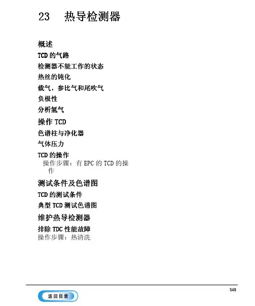
60
50 参比气 流量 40 (mL/min)
30
氢气
氦气 氮气
20
10 0 压力 (psig) 10 (kPa) 69.0
20
30
40
50
60
137.9 206.8 275.8 344.7 413.7
20 18 16 14 尾吹气 12 流量 10 (mL/min)9 6 4
2 压力 (0psig)
图 80.
TCD 控制表
选择合适的气体
557
操作 TCD
热导检测器 TCD 的操作
操作步骤 有 EPC 的 TCD 的操作
此操作确保检测器的气路已连接 系统无漏气及柱已安装完好 在使用检测器 之前要设定柱箱温度 进样口温度和进样口 / 柱流量
1. 按 [Front Det] 或 [Back Det], 打开检测器控制表
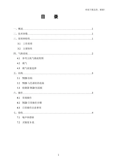
出口 比例阀
压力 传感器
PS
压力 控制回路
限流器
PS
参比 切换阀 尾吹气流量
热导检测器 TCD 的气路
出口
图 77.
TCD 气路
检测器不能工作的状态
• 温度设定低于 150 • 热丝断开或短路 • 参比气流设定为 0
552
概述
热导检测器 热丝的钝化
热丝的钝化
为了防止氧气损害热丝 TCD 检测器的钨 铼热丝已经进行了化学钝化处理 可是 像酸和卤代化合物等化学活泼物质仍可以腐蚀热丝 直接的后果就是 由于热丝阻值的变化导致检测器灵敏度发生永久的变化
558
测试条件及色谱图
热导检测器 TCD 的测试条件
测试条件及色谱图
本节列出了一个测试样品色谱图的典型示例 它可以用作仪器性能的一般性指 南
TCD说明书也适用带放大9790III
欢迎下载支持,谢谢!目录一、概述 (1)二、技术参数 (1)三、原理和特性 (1)3.1 工作原理3.2 主要特性四、气路系统 (2)4.1 参考主机气路流程图4.2 载气4.3 载气流量选择五、结构 (3)5.1 TCD结构5.2 TCD与色谱柱的连接5.3 检测器TCD恒流板六、操作 (3)6.1 常规操作6.2 TCD日常操作步骤6.3 日常操作注意事项七、验收 (4)7.1 噪声和漂移7.2 灵敏度S值一、概述热导检测器(TCD)是气相色谱仪上应用最广泛的一种检测器之一,它结构简单,性能稳定,灵敏度适宜,对各种物质都有响应,尤其适应常规分析,气体分析。
本章主要叙述GC9790Ⅲ型气相色谱仪热导检测器(TCD)的原理、安装、使用、及应用中应注意事项等内容。
GC9790Ⅲ型气相色谱仪热导检测器(TCD)主要由三个部件组成:一、(TCD)热导池块体及灵敏元件二、热导池加热及温度控制器(由主机板控制)三、热导池桥路恒流源二、技术参数TCD池体:半扩散式,四臂铼钨丝桥路电源:恒流控制电路桥流:0~200mA,(60~100Ω灵敏元件)0~150mA,(100~150Ω灵敏元件)(H2或He作载气,电源增量单位1 mA)温度控制范围:室温上30℃~350℃,增量为1℃(一般使用为柱温+10℃~50℃) 温度控制精度:±0.03℃炉子绝对温度精度:为设定温度±0.5%灵敏度S值:≥2000mv·ml/mg(nC16) ;≥8000mv·ml/mg(nC16)(带放大)噪声水平:≤20uv漂移:≤50uv/15min动态范围:≥104~105TCD过载保护功能:当超量样品进入TCD或TCD未通载气引起TCD铼钨丝温度过高时,TCD电流自动切断。
三、原理和特性3.1 工作原理TCD检测器基本原理:是基于不同物质与载气之间有不同的热传导率,当不同物质流经池体时,由于热丝温度受到响应,阻值发生变化,使桥路失去平衡,由之输出信号。
PhilipsCD机光头、DAC、IC机芯对照表
PhilipsCD机光头、DAC、IC机芯对照表PHILIPS CD100 2 x TDA1540D CDM-0PHILIPS CD200 2 x TDA1540D – SAA7030 CDM-0PHILIPS CD202 2 x TDA1540D – SAA7030 CDM-0PHILIPS CD300 2 x TDA1540D – SAA7030 CDM-0PHILIPS CD303 2 x TDA1540D – SAA7030 CDM-0PHILIPS LHH2000 2 x TDA1540P – SAA7030 CDM-0 / CDM-1PHILIPS CD101 2 x TDA1540D CDM-1PHILIPS CD104 2 x TDA1540P – SAA7030 CDM-1PHILIPS CD204 2 x TDA1540P – SAA7030 CDM-1PHILIPS CD304 2 x TDA1540P – SAA7030 CDM-1PHILIPS CD304 Mk II TDA1541-S1 (Single Crown) CDM-1PHILIPS CD960 TDA1541 – SAA7220 – SAA7210 CDM-1PHILIPS LHH1000 TDA1541A-S1 (Double Crown) CDM-1 PHILIPS CD-80 TDA1541A-S1 (Single Crown) CDM-1 Mk IIPHILIPS CD-85 TDA1541A-S1 (Single Crown) CDM-1 Mk IIPHILIPS CD880 TDA1541A-S1 (Single Crown) CDM-1 Mk IIPHILIPS CDD882 It’s a Transport – SAA7210P CDM-1 Mk II PHILIPS CD151 2 x TDA1540P – SAA7030 CDM-2PHILIPS CD207 TDA1541 CDM-2PHILIPS CD372 TDA1541 CDM-2PHILIPS CD450 TDA1541 – SAA7220P/A CDM-2PHILIPS CD640 TDA1541 – SAA7220P/A CDM-2PHILIPS CD350 2 x TDA1540P – SAA7030 CDM-2 / CDM-2/10PHILIPS CD782 TDA1541 – SAA7220P/A CDM-2 / CDM-4PHILIPS CD373 TDA1541 CDM-2 / CDM-4/11PHILIPS CD470 TDA1541 CDM-2 / CDM-4/11PHILIPS CD471 TDA1541 CDM-2 / CDM-4/11PHILIPS CD473 TDA1541 CDM-2 / CDM-4/11PHILIPS CD660 TDA1541 – SAA7220P/A CDM-2 / CDM-4/11PHILIPS CD771 TDA1541 – SAA7220P/A CDM-2 / CDM-4/11PHILIPS CD150 2 x TDA1540P – SAA7030 CDM-2/10PHILIPS CD160 TDA1541 – SAA7220P/A CDM-2/10PHILIPS CD350 Mk II TDA1541-S1 (Single Crown) CDM-2/10 / CDM-2/29PHILIPS CD360 TDA1541 CDM-2/10 / CDM-2/29PHILIPS CD670 TDA1541 –SAA7220P/A CDM-2/10 / CDM-4/11PHILIPS CD460 TDA1541 / TDA1543 – SAA7220P/A CDM-2/10 / CDM-4/25PHILIPS CD650 TDA1541 – SAA7220P/A – SAA7210 CDM-2/10 / CDM-4/25PHILIPS CD371 TDA1541 CDM-2/29 / CDM-4/11PHILIPS CD130 TDA1543 CDM-4PHILIPS LHH500 2 x SAA7321GP – SAA7220P/B CDM-4 MetallicPHILIPS LHH500R 1 x TDA1547 –SM5803AP CDM-4 MetallicPHILIPS LHH600 TDA1547 (DAC7) CDM-4 MetallicPHILIPS LHH700 2 x TDA1547 –SM5803APT CDM-4MetallicPHILIPS LHH800R 1 x TDA1547 (DAC7) –SM5803APT CDM-4 MetallicPHILIPS LHH900R 1 x TDA1547 (DAC7) CDM-4 Metallic PHILIPS CD472 TDA1541 – SAA7220P/A CDM-4/11PHILIPS AK 601 TDA1543A CDM-4/19PHILIPS AK 630 SAA7341 CDM-4/19PHILIPS CD115 TDA1543 CDM-4/19PHILIPS CD210 TDA1543 CDM-4/19PHILIPS CD230 TDA1543 CDM-4/19PHILIPS CD380 TDA1543 CDM-4/19PHILIPS CD480 TDA1541 / TDA1543 – SAA7220 CDM-4/19 PHILIPS CD482 TDA1543 – SAA7220P/A CDM-4/19PHILIPS CD500 TDA1543 CDM-4/19PHILIPS CD502 TDA1543 CDM-4/19PHILIPS CD581 TDA1541 CDM-4/19PHILIPS CD582 TDA1541 – SAA7220P/A CDM-4/19PHILIPS CD584 TDA1541A – SAA7220P/B CDM-4/19PHILIPS CD600 TDA1543 – SAA7220 CDM-4/19PHILIPS CD604 TDA1543 CDM-4/19PHILIPS CD605 SAA7321GP CDM-4/19PHILIPS CD610 TDA1543 – SAA7220 CDM-4/19PHILIPS CD614 TDA1543 CDM-4/19PHILIPS CD615 SAA7321GP CDM-4/19PHILIPS CD618 SAA7323 CDM-4/19PHILIPS CD620 TDA1541 CDM-4/19PHILIPS CD624 SAA7321GP CDM-4/19PHILIPS CD630 TDA1541A – SAA7220P/B CDM-4/19PHILIPS CD634 SAA7321 CDM-4/19PHILIPS CD780 TDA1541A – SAA7220 CDM-4/19PHILIPS CD820 TDA1541A – SAA7220P/B CDM-4/19PHILIPS CD824 SAA7321GP CDM-4/19PHILIPS CD834 SAA7321GP CDM-4/19PHILIPS CD840 2 x SAA7321GP – SAA7220P/B CDM-4/19 PHILIPS CD850 2 x SAA7321GP – SAA7220P/B CDM-4/19 PHILIPS CD850 Mk II SAA7350 CDM-4/19PHILIPS CDC875 TDA1541A CDM-4/19PHILIPS CDD461 TDA1543 CDM-4/19PHILIPS CD586 TDA1541A CDM-4/20PHILIPS CDC486 TDA1543 CDM-4/20PHILIPS CD830 TDA1541A-R1 –SAA7220P/B CDM-4/CompositePHILIPS LHH100M TDA1547 – SM5840 CDM-9PHILIPS LHH200R TDA1547 (DAC7) CDM-9PHILIPS LHH300 SAA7321 CDM-9PHILIPS LHH300R TDA1547 (DAC7) – SAA7350 CDM-9PHILIPS CD930 SAA7350 CDM-9/44PHILIPS CD940 SAA7350GP – SM5840AS CDM-9/44PHILIPS CD950 TDA1547 – SAA7350 CDM-9/44PHILIPS CD931 SAA7350 CDM-9/65PHILIPS CD951 TDA1547 – SAA7350 – SAA7310 CDM-9/65 PHILIPS DAC960 1 x TDA1541A It’s a DACPHILIPS CD722 TDA1545A VAM 1201PHILIPS CD723 TDA1545 – SAA7378 VAM 1201PHILIPS CD713 TDA1545A VAM 1202PHILIPS CD692 SAA7341GP CDM 12PHILIPS CD721 TDA1545A CDM 12PHILIPS CD732 SAA7341 CDM 12PHILIPS CD690 SAA7341 CDM 12.1PHILIPS CD710 TDA1545A – SAA7345 CDM 12.1PHILIPS CD720 TDA1545A CDM 12.1PHILIPS CD750 TDA1541A / TDA1549 CDM 12.1PHILIPS CD753 TDA1549 –SAA7378 CDM 12.1 / VAM 1201PHILIPS CD163 TDA1545A CDM 12.1/05PHILIPS CD751 TDA1549 – SAA7378 CDM 12.1/05PHILIPS CD910 SAA7341GP CDM 12.1/05PHILIPS CD911 SAA7341GP CDM 12.1/05PHILIPS CD920 SAA7341GP CDM 12.1/05PHILIPS CDC745 SAA7341GP CDM 12.1/05PHILIPS CD465 TDA1541PHILIPS CD580 TDA1541CDM-2CDM3CDM4普通板CDM4 工业版。
防腐型雷达物位计型号
防腐型雷达物位计型号防腐型雷达物位计型号1. 简介防腐型雷达物位计是一种用于测量液体、粉末和颗粒物料的高精度非接触式测量仪器。
它采用微波技术,能够在恶劣环境下进行稳定的工作,具有高精度、高可靠性、高稳定性等优点,被广泛应用于化工、石油、制药、食品等行业。
2. 型号目前市场上常见的防腐型雷达物位计型号有:(1)SITRANS LR560:西门子公司生产的一款防腐型雷达物位计,适用于各种液体和固体介质的非接触式测量。
(2)Rosemount 5400:艾默生公司生产的一款防腐型雷达物位计,适用于化学品、石油和天然气等行业。
(3)Guidense TDR2000:美国Vega公司生产的一款防腐型雷达物位计,适用于各种液体和固体介质的非接触式测量。
3. 特点(1)耐腐蚀性强:采用特殊材料制造,能够在酸碱等腐蚀性介质中长期稳定工作。
(2)测量范围广:适用于各种液体、粉末和颗粒物料的非接触式测量,可满足不同行业的需求。
(3)高精度:采用微波技术,具有高精度、高可靠性和高稳定性等优点。
(4)易安装:无需接触物料,安装简便、维护方便。
4. 应用防腐型雷达物位计广泛应用于化工、石油、制药、食品等行业。
具体应用包括:(1)化工行业:测量各种液体和固体介质的液位、料位和界面。
(2)石油行业:测量储罐内的原油、天然气等介质的液位和料位。
(3)制药行业:测量各种液体药剂的液位和料位。
(4)食品行业:测量各种粉末和颗粒物料的料位。
5. 注意事项使用防腐型雷达物位计时需要注意以下事项:(1)正确选择型号:根据实际需求选择合适的型号。
(2)安装位置:应选择在介质表面以上,以免影响测量精度。
(3)维护保养:定期检查和清洁物位计,确保其正常工作。
(4)避免干扰:防止外部电磁场等干扰物位计的正常工作。
热导检测器(TCD)
热导检测器(TCD)一.概述0.TCD是第一个用于气相色谱仪的检测器,在没有用于气相色谱分析之前称卡它计。
0.随着气相色谱分析技术的发展,后来又出现了许多灵敏度高,选择性强的检测器,虽然在很多方面胜过TCD,可是并不能取代TCD。
0.在长期实践中,人们不断改造完善它,特别是通过选用新热丝材料、减少了池容积、改进气路形式、提高控温精度,采用新的桥路供电和加前置放大电路等,使现代的TCD已非昔日可比。
1.TCD和其它检测器相比,具有结构简单,对所有物质都有信号,性能稳定可靠、定量准确、不破坏样品和最小检测浓度可达0.1×10⁻⁶ml/ml,目前已能和大口径毛细管分析相配用等,在气相色谱仪配置中仅次于FID。
0.目前商品GC配备的TCD,有常规TCD和单臂热丝调制TCD,前者占了绝大部分。
2.配置单臂热丝调制TCD目前仅有安捷伦公司。
其简单的工作原理是单热丝为电桥的一个臂,组成恒热丝温度检测电路,它用时域差,从一个臂热丝上分别获得测量和参考信号,采集速率为80 H Z,最后用电子器件将这种脉冲式的色谱信号解调为一般的色谱信号峰,再作数据处理。
二.TCD工作原理气体具有热传导作用,而不同的物质有不同的热传导系数。
热导检测器就是根据不同物质热传导系数的差别而设计的。
但是要直接测量这种绝对值的差异是非常困难的,一般都采用间接测量法即热导池电桥法。
根据热学和电学原理以及实验验证,单臂热导池的桥路输出信号E0服从下列关系:In(r0/r f) ɑER0I2 1 1E0=[-------------]·[------------]·[X S(------- - -----------)]2πL 4J λSλq式中:r0——池孔内经r f——热丝直径L——热丝长度R0——在0℃时,热丝元件的电阻值J——热的功当量E——加在电桥上的电压I——通过热丝的电流α——热丝的电阻温度系数X s ———组分在载气中的克分子数λs——组分的热导率λg——载气的热导率从式中清楚地看出,影响输出信号的各参数可归纳为三部分:第一池槽结构——几何因子;第二电路参数——电学因子;第三热量参数——热传导性因子;要提高TCD的灵敏度,即增大E0,可有以下途径:2.从几何因子分析采用细的金属热丝做热丝元件、增大池孔内经和缩短热丝长度。
上海永大电梯-新故障码解说
Relay的LED Check: (1)SFCR Relay ON 时,50B LED亮。 (2)SFCR Relay OFF 时,50B LED灭。
Relay状态Check: SFCR Relay卡住,接点曲折、熔着,配线短路等确认。
PCB与FIOGB PCB之间排线;MUD及FOD Connect有无接触不良Check。
500 ms 内 OFF,则检出异常。
复归方 式
故障排除,FFB 切 OFF-ON 后,操作 MODE 2 清除 TCD,方能恢复运转。
调查项目:
1.入力Buffer有无ON故障Check: 主MXBCTT ($CA00)、从SXBCTT($CD20)其Data是否随着BCTT接触器之ON-OFF同步动作。 ※MXBCTT ($CA00)、SXBCTT ($CD20)皆操作 MODE 22 观察。
A1
TCD 50 高速 OVER SPEED
B1
TCD 51 速度偏差异常
B1
TCD 52 MCTT 不闭合故障
A1
TCD 53 BCTT 不闭合故障
A1
TCD 54 RE 故障(U,V,W 相磁极角度异常)
A1
TCD 55 马达电流检出回路异常
A1
TCD 57 两段式电源回路异常
A1
TCD 58 DLAN 当机
主接触器状态Check: MCTT主接触器卡住,接点曲折、熔着,配线短路等确认。
PCB与FIOGB PCB之间排线;MUD及FOD Connect有无接触不良Check。
PCB更换 第1项或第2项有状况,而第4项良好时,表示FIOGB出力Buffer不良,更换FIOGB PCB。
PCB 更换 更换 FIOGB PCB 后,仍有异常发生,表示 MPUGB PCB 不良,更换 MPUGB PCB。