Q67000-A6024中文资料
PW7000-系列Access控制系统用户指南说明书

PW7000-SERIES T he PW7000-Series AccessControl System is an advancedaccess control hardwarearchitecture capable of providingsolutions for large enterpriseapplications.Controllers and I/O BoardsFEATURES AND BENEFITSSECURE• L atest encryption standard support with TLS1.2 and OSDP (V2) Secure Channel Protocol• E mbedded Crypto Memory Chip to protect sensitive data VERSATILE• B ackwards compatible withPW6000* controllers, readerboards, I/O boards andenclosures*• O n-board support for up to2 readers (1 Door) for bothPW7K1IC and PWLP1501COMPREHENSIVE• W ide variety of nativeintegrations includingwireless locks and destinationdispatch elevators• E xtensive customizationincluding If / Then macrocapabilitiesADAPTABLE• M odular design allowscontrollers and downstreamboards to be mixed to fit themost demanding customerrequirements• F lexible power options forPWLP1501 and PWMR62Eincluding PoE and PoE+The Intelligent Controllers provide power and flexibility with an embedded Linux OS, improved processor and increased memory as well as onboard crypto chip which adds an additional layer of security to sensitive data.The PW-series controllers support a combination of I/O and reader boards to monitor alarm input points, relay output points and interface with access control readers. By offering a modular design, the system can be tailored to meet a wide range of applications while optimizing cost and installation.The PW7K1IC comes with 2 on-board reader ports that support multiple reader communication protocols including Wiegand and OSDP (V2) Secure Channel Protocol (SCP). OSDP SCP is now supported across all the intelligent controller and reader board hardware. PW7000-series control panels and I/O boards are backwards compatible with PW6000-Series*.PW7000-Series Access Control System.The PW-series controllers support a combination of I/O and reader boards to monitor alarm input points, relay output points and interface with access control readers.* Note:P W6K1IC board is based on Mercury’s EP2500, PW7K1IC board is based on Mercury’s LP1502 and includes extra reader/door connections.PW7K1IC board has 1 RS485 downstream bus. All Honeywell PW7000 Form Factor and Honeywellbranded Mercury boards are backwards compatible with existing PW5000/PW6000 Enclosures.SPECIFICATIONSPW7K1IC PW7K1R2PW7K1OUT PW7K1INFUNCTIONAL DESCRIPTIONThe multi-port PW7K1IC is a dual card reader panel for controlling two connected doors and managing up to 64 doors/openings. Built with Authentic Mercury Technology (LP1502), the intelligent controller uses on-board Ethernet port to connect to the Honeywell server-based platform ‘Pro-Watch’.The intelligent controller performs access control, alarmmanagement and scheduled operations, all in single package. With native connectivity*, the high-performance PW7K1IC functions independently of the host for performing numerous access control applications and supports OSDP, OSDP Secure Channel, keypads, biometric readers, Wiegand, clock and data, F/2F and supervised F/2F reader technologies.System configuration and setup are provided through Mercury software applications/tools. For a comprehensive and open Honeywell access control platform, and a reliable hardware platform running in a secure environment, the PW7K1IC is the clear solution. It delivers a complete security and access control solution as well as innovative application extensions, interoperability and data security.* Note: F ull native PW7000 mode (On-board Reader/Door support on ICboard; OSDP (V2) Secure Channel; OSDP 4 readers; OSDP Push FW) Coming soon in Pro-Watch.ORDERINGHSI-PW7K-02-ME(1220)DS-C© 2020 Honeywell International Inc.For More Information/me Honeywell Commercial Security Emaar Business Park, Building 2Sheikh Zayed Road P.O. Box 232362Dubai, United Arab Emirates Tel: +971 4 450 5800Email:***************************。
天诚通信-铜产品

目录超五类非屏蔽信息模块 (5)超五类非屏蔽直通信息模块 (6)超五类屏蔽信息模块 (7)超五类屏蔽直通信息模块 (8)六类非屏蔽信息模块 (9)六类屏蔽信息模块 (10)超六类非屏蔽信息模块 (11)超六类非屏蔽信息模块 (12)超六类屏蔽信息模块 (13)超五类非屏蔽免打线水晶头 (14)经典系列平口面板 (15)雅典系列平口面板 (16)雅典系列斜口面板 (17)雅典系列有线电视面板 (18)数据语音电视三合一面板 (19)二位方形光纤开起式地脚插座 (20)三位方形信息弹起式地脚插座 (21)三位圆形信息弹起式地脚插座 (22)三位方形信息开起式地脚插座 (23)三位圆形信息开起式地脚插座 (24)五孔方形弹起式电源插座 (25)五孔圆形弹起式电源插座 (26)六孔方形弹起式电源插座 (27)六位桌面型地脚插座 (28)地插功能配件 (29)24口非屏蔽空配线架 (31)24口非屏蔽空配线架(带防尘门) (32)24口超五类非屏蔽配线架 (33)24口超五类非屏蔽角型配线架 (34)24口超五类屏蔽配线架 (35)24口六类非屏蔽配线架 (36)24口六类非屏蔽角型配线架 (37)24口六类屏蔽配线架 (38)24口超六类非屏蔽配线架 (39)24口超六类屏蔽配线架 (40)0.5U24口超五类非屏蔽配线架 (41)0.5U24口六类非屏蔽配线架 (42)0.5U24口六类屏蔽配线架 (43)封闭式理线架 (44)智能电子配线架 (45)智能电子配线架控制主机 (46)智能电子扫描仪 (47)110理线架 (49)110连接块 (50)110跳线 (51)110转RJ45跳线 (52)超五类非屏蔽跳线 (53)超五类屏蔽跳线 (54)六类非屏蔽跳线 (55)六类屏蔽跳线 (56)超六类非屏蔽跳线 (57)超六类屏蔽跳线 (58)超五类屏蔽防水跳线 (59)六类屏蔽防水跳线 (60)五类1对非屏蔽线缆 (61)五类2对非屏蔽线缆 (62)五类4对非屏蔽线缆 (63)超五类4对非屏蔽线缆 (64)超五类4对屏蔽线缆 (65)超五类4对双屏蔽线缆 (66)六类4对非屏蔽线缆 (67)六类4对屏蔽线缆 (68)六类4对双屏蔽线缆 (69)六类4对对对屏蔽线缆 (70)超六类4对非屏蔽线缆 (71)超六类4对屏蔽线缆 (72)超六类4对双屏蔽线缆 (73)超六类4对对对屏蔽线缆 (74)七类4对屏蔽线缆 (75)五类4对非屏蔽室外线缆 (76)五类4对屏蔽室外线缆 (77)超五类4对屏蔽室外线缆 (78)超五类4对屏蔽室外线缆 (79)六类4对非屏蔽室外线缆 (80)六类4对屏蔽线缆 (81)五类4对双护套非屏蔽线缆 (82)超五类4对双护套非屏蔽线缆 (83)超五类4对双护套屏蔽线缆 (84)3类非屏蔽室内线缆(50对) (85)5类非屏蔽室内线缆(25对) (86)3类屏蔽室内线缆(50对) (87)5类屏蔽室内线缆(25对) (88)3类非屏蔽室外线缆(50对) (89)5类非屏蔽室外线缆(25对) (90)3类屏蔽室外线缆(50对) (91)5类屏蔽室外线缆(50对) (92)市话充油通信电缆(50对) (94)市话重铠通信电缆(50对) (95)超五类非屏蔽信息模块产品说明:应用范围:1000 BASE-TX千兆以太网;100 BASE-TX快速以太网;10 BASE-T以太网;语音,视频及其它应用网络工作区域内语音、数据信息的连接。
佳乐科仪变频器JR7000说明书

目录第1章序言 ............................... 错误!未定义书签。
特别需要注意的事项....................... 错误!未定义书签。
安全注意事项标志......................... 错误!未定义书签。
警告标签................................. 错误!未定义书签。
开箱检查................................. 错误!未定义书签。
产品搬运................................. 错误!未定义书签。
产品保存................................. 错误!未定义书签。
产品保修................................. 错误!未定义书签。
第2章产品概述 ........................... 错误!未定义书签。
JR7000综合技术指标....................... 错误!未定义书签。
输入输出特性........................... 错误!未定义书签。
外围接口特性........................... 错误!未定义书签。
技术性能特性........................... 错误!未定义书签。
功能特性............................... 错误!未定义书签。
变频器铭牌说明........................... 错误!未定义书签。
变频器系列型号........................... 错误!未定义书签。
变频器各部件名称说明..................... 错误!未定义书签。
第3章安装 ............................... 错误!未定义书签。
安装环境................................. 错误!未定义书签。
daq 6024e 说明书
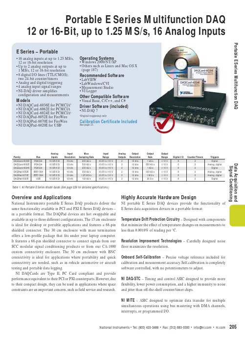
Overview and ApplicationsNational Instruments portable E Series DAQ products deliver the same functionality available in PCI and PXI E Series DAQ devices –in a portable format.The DAQPad devices are hot swappable and available in up to three different configurations.The 15 cm enclosure is ideal for desktop or portable applications and features a 68-pin shielded connector.The 30 cm enclosure with mass termination offers a low-profile package that fits under your laptop computer. It features a 68-pin shielded connector to connect signals from our SCC modular signal conditioning products or from our CA-1000 custom connectivity enclosure.The 30 cm enclosure with BNC connectivity is ideal for applications where portability and quick connectivity are needed,such as in-vehicle automotive or aircraft testing and portable data logging.NI DAQCards are Type II,PC Card compliant and provide performance equivalent to their PCI or PXI counterparts.However,due to their compact design,they can be used in applications where space constraints are an important concern,such as field service and research.Highly Accurate Hardware DesignNI portable E Series DAQ devices provide the functionality of E Series data acquisition devices in a portable format:Temperature Drift Protection Circuitry– Designed with components that minimize the effect of temperature changes on measurements to less than 0.0010% of reading per °C.Resolution Improvement Technologies– Carefully designed noise floor maximizes the resolution.Onboard Self-Calibration– Precise voltage reference included for calibration and measurement accuracy.Self-calibration is completely software controlled,with no potentiometers to adjust.NI DAQ-STC– Timing and control ASIC designed to provide more flexibility,lower power consumption,and a higher immunity to noise and jitter than off-the-shelf counter/timer chips.NI MITE– ASIC designed to optimize data transfer for multiple simultaneous operations using bus mastering with DMA channels, interrupts,or programmed I/O.•16 analog inputs at up to 1.25 MS/s, 12 or 16-bit resolution•Up to 2 analog outputs at up to1 MS/s,12 or 16-bit resolution•8 digital I/O lines (TTL/CMOS); two 24-bit counter/timers •Analog and digital triggering•4 analog input signal ranges•NI-DAQ driver simplifies configuration and measurements Models•NI DAQCard-6036E for PCMCIA1•NI DAQCard-6062E for PCMCIA •NI DAQCard-6024E for PCMCIA1•NI DAQPad-6052E for FireWire •NI DAQPad-6070E for FireWire •NI DAQPad-6020E for USB1Operating Systems •Windows 2000/NT/XP•Others such as Linux and Mac OS X (page 187)Recommended Software •LabVIEW•LabWindows/CVI •Measurement Studio•VI LoggerOther Compatible Software •Visual Basic,C/C++,and C# Driver Software (included)•NI-DAQ 71Digital triggering onlyCalibration Certificate Included See page 21.E Series – Portable Portable E Series Multifunction DAQ12 or 16-Bit, up to 1.25 MS/s, 16 Analog InputsPortable E Series Multifunction DAQData Acquisition and Signal ConditioningP o r t a b l e E S e r i e s M u l t i f u n c t i o n D A QD a t a A c q u i s i t i o n a n d S i g n a l C o n d i t i o n i n gPortable E Series Multifunction DAQ12 or 16-Bit, up to 1.25 MS/s, 16 Analog InputsNI PGIA – Measurement and instrument class amplifier that guarantees settling times at all gains.Typical commercial off-the-shelf amplifier components do not meet the settling time requirements for high-gain measurement applications.PFI Lines – Eight programmable function input (PFI) lines that can be used for software-controlled routing of intraboard digital and timing signals.RSE Mode – In addition to differential and nonreferenced single-ended modes,NI portable E Series devices offer referenced single-ended (RSE) mode for use with floating signal sources in applications with channel counts higher than eight.Onboard Temperature Sensor – Included for monitoring the operating temperature of the device to ensure that it is operating within the specified range.Analog and Digital Triggering – Some portable E Series devices provide the ability to set a trigger based on the level of an analog signal,in addition to the ability to trigger off an edge of a digital signal.High-Performance, Easy-to-Use Driver SoftwareNI-DAQ is the robust driver software that makes it easy to access the functionality of your data acquisition hardware,whether you are a beginning or advanced user.Helpful features include:Automatic Code Generation – The DAQ Assistant is an interactive guide that steps you through configuring,testing,and programming measurement tasks and generates the necessary code automatically for LabVIEW,LabWindows/CVI,or Measurement Studio.Cleaner Code Development – Basic and advanced software functions have been combined into one easy-to-use yet powerful set to help you build cleaner code and move from basic to advanced applications without replacing functions.High-Performance Driver Engine – Software-timed single point input (typically used in control loops) with NI-DAQ achieves rates of up to 50 kHz.NI-DAQ also delivers maximum system throughput I/O with a multithreaded driver.Test Panels – With NI-DAQ,you can test all of your device functionality before you begin development.Scaled Channels – Easily scale your voltage data into the proper engineering units using the NI-DAQ measurement-ready virtual channels by choosing from a list of common sensors and signals or creating your own custom scale.LabVIEW Integration – All NI-DAQ functions use the waveform data type,which carries acquired data and timing information directly into more than 400 LabVIEW built-in analysis routines for display of results in engineering units on a graph.Portable E Series Multifunction DAQ12 or 16-Bit, up to 1.25 MS/s, 16 Analog InputsPortable E Series Multifunction DAQData Acquisition and Signal ConditioningWorldwide Support and ServicesNI provides you with a wealth of resources to help you get your application up and running more quickly,including:Technical Support – Purchase of NI hardware or software gives you access to application engineers all over the world as well as Web resources with more than 3,000 measurement examples and more than 9,000 KnowledgeBase entries.– /supportCalibration – Includes NIST-traceable basic calibration certificates,services for ANSI/NCSL-Z540 and periodic calibration –/calibrationExtended Warranty – Meet project life-cycle requirements and maintain optimal performance in a cost-effective way – /services For more information on NI services and support, please visit /servicesVisit /oem for information on our quantity discounts.For information on device support in NI-DAQ 7,visit /dataacquisitionRecommended AccessoriesSignal conditioning is required for sensor measurements or voltage inputs greater than 10 V.National Instruments SCXI is a versatile,high-performance signal conditioning platform,intended for high-channel-count applications.NI SCC products provide portable,flexible signal conditioning options on a per-channel basis.Both signal conditioning platforms are designed to increase the performance and reliability of your DAQ System,and are up to 10X more accurate than terminal blocks (please visit /sigcon for more details).Refer to the table below for more information:NI DAQCard-6036E....................................................................778561-01NI DAQCard-6062E....................................................................777976-01NI DAQCard-6024E....................................................................778269-01NI DAQPad-6052E 1for FireWire (IEEE 1394) withMass termination,AC Adapter 2,and 4 m FireWire cableUS 120 V AC........................................................................778535-01Universal Euro 240 V AC....................................................778535-04United Kingdom 240 V AC.................................................778535-06BNC termination,AC Adapter 2,and 4 m FireWire cableUS 120 V AC........................................................................778536-01Universal Euro 240 V AC....................................................778536-04United Kingdom 240 V AC.................................................778536-06NI DAQPad-6070E for FireWire 1(IEEE 1394) withMass termination,AC Adapter 2,and 4 m FireWire cableUS 120 V AC........................................................................777867-01Universal Euro 240 V AC....................................................777867-04United Kingdom 240 V AC.................................................777867-06BNC termination,AC Adapter 2,and 4 m FireWire cableUS 120 V AC........................................................................777803-01Universal Euro 240 V AC....................................................777803-04United Kingdom 240 V AC.................................................777803-06NI DAQPad-6020E for USB 1in15 cm enclosure with AC Adapter 2,and 1 m USB cableUS 120 V AC........................................................................777474-01Universal Euro 240 V AC....................................................777474-04United Kingdom 240 V AC.................................................777474-06Japan 120 V AC....................................................................777474-0730 cm enclosure with mass termination,AC Adapter 2,and 1 m USB cableUS 120 V AC....................................................................777704-01Universal Euro 240 V AC................................................777704-04United Kingdom 240 V AC............................................777704-06Japan 120 V AC................................................................777704-0730 cm enclosure with BNC termination AC Adapter 2,and 1 m USB cableUS 120 V AC....................................................................777703-01Universal Euro 240 V AC................................................777703-04United Kingdom 240 V AC............................................777703-06Japan 120 V AC................................................................777703-07Includes NI-DAQ driver software and calibration certificate.1Windows 2000/XP only for DAQPads2The AC Adapter is universal.The difference between these kits is the power cable.DAQPad AccessoriesBP-1 rechargeable battery pack120 V AC charger........................................................776896-01230 V AC charger........................................................776896-31Rack-mount kit ............................................................777665-01Stacking kit....................................................................777666-01PCI-to-IEEE 1394 adapter ............................................Please call CardBus-to-IEEE 1394 adapter ....................................Please callBUY ONLINE!Visit /dataacquisitionOrdering InformationSpecifications (continued)M u l t i f u n c t i o n D A Q A b s o l u t e A c c u r a c y S p e c i f i c a t i o n sD a t a A c q u i s i t i o n a n d S i g n a l C o n d i t i o n i n gMultifunction DAQAbsolute Accuracy Specifications12-Bit E Series MultifunctionDAQ Specifications12-Bit E Series SpecificationsData Acquisition andSignal ConditioningThese specifications are typical for 25 °C unless otherwise noted.Analog InputAccuracy specifications...................................See page 228.Input CharacteristicsResolution.........................................................12 bits, 1 in 4,096Maximum working voltage(signal + common mode)...........................Input should remain within ±11 V of groundPCI, PXI, DAQPad for FireWire..................DMA, interrupts, programmed I/O DAQCard, DAQPad for USB.......................Interrupts, programmed I/ODMA modesPCI, PXI, DAQPad for FireWire..................Scatter-gather (single-transfer, demand transfer)Configuration memory size..............................512 wordsTransfer CharacteristicsSpecifications – NI 607xE, NI 6062E, NI 6040E, NI 602xE12-B i t E S e r i e s S p e c i f i c a t i o n sD a t a A c q u i s i t i o n a n dS i g n a l C o n d i t i o n i n g12-Bit E Series Multifunction DAQ SpecificationsAmplifier CharacteristicsInput bias current.............................................±200 pA Input offset current..........................................±100 pA Dynamic CharacteristicsSpecifications – NI 607xE, NI 606xE, NI 6040E, NI 602xE (continued)12-Bit E Series MultifunctionDAQ Specifications12-Bit E Series SpecificationsData Acquisition and Signal ConditioningAnalog OutputOutput CharacteristicsResolution.........................................................12 bits, 1 in 4,096Maximum update rateData transfersPCI, PXI, DAQPad for IEEE 1394................DMA, interrupts, programmed I/O DAQCard, DAQPad for USB.......................Interrupts, programmed I/O DMA modesPCI, PXI, DAQPad.......................................Scatter-gather (single transfer, demand transfer)Transfer CharacteristicsRelative accuracy After calibration6062E, DAQCard-6024E......................±0.5 LSB typical, ±1.0 LSB maximum All others............................................±0.3 LSB typical, ±0.5 LSB maximum Before calibration......................................±4 LSB maximumDNLAfter calibration6062E, DAQCard-6024E......................±0.5 LSB typical, ±1.0 LSB maximum All others............................................±0.3 LSB typical, ±1.0 LSB maximum Before calibration......................................±3 LSB maximumMonotonicity....................................................12 bits, guaranteed after calibration Gain error (relative to external reference)6062E, 6020E.............................................±0.5% of output maximum, not adjustable 607xE, 6040E.............................................0 to 0.67% of output maximum, not adjustableVoltage OutputOutput coupling................................................DCOutput impedance............................................0.1 ΩmaximumCurrent drive.....................................................±5 mA maximumProtection.........................................................Short-circuit to ground Power-on state.................................................0 V (±200 mV)External Reference InputRange.........................................................11 VOvervoltage protection607xE, 6062E, 6040E..........................±25 V powered on, ±15V powered off 6020E..................................................±35 V powered on, ±25V powered off Input impedance........................................10 k ΩBandwidth (-3 dB)607xE, 6040E...................................... 1 MHz 6062E..................................................50 kHz 6020E..................................................300 kHzDynamic CharacteristicsNoise................................................................200 µV rms , DC to 1 MHz Glitch energy magnitude (at mid-scale transition)StabilityGain temperature coefficient (except 6024E, 6025E)External reference.....................................±25 ppm/°CSpecifications – NI 607xE, NI 606xE, NI 6040E, NI 602xE (continued)12-B i t E S e r i e s S p e c i f i c a t i o n sD a t a A c q u i s i t i o n a n d S i g n a l C o n d i t i o n i n g12-Bit E Series Multifunction DAQ SpecificationsDigital I/OPower-on state.................................................Input; (high-impedance)Digital logic levels P0.<0..7>P1.<0..7>, P2.<0..7>, P3.<0..7>Maximum with NI-DAQ, system dependentConstant sustainable rate................................ 1 to 10 kwords/s, system dependentTiming I/ONumber of channelsUp/down counter/timers...........................2Frequency scaler........................................1ResolutionUp/down counter/timers...........................24 bits Frequency scaler........................................ 4 bits Compatibility.................................................... 5 V/TTLBase clocks availableUp/down counter/timers...........................20 MHz and 100 kHz Frequency scaler........................................10 MHz and 100 kHz Base clock accuracy.........................................±0.01%Maximum source frequencyUp/down counter/timers...........................20 MHzMinimum source pulse duration......................10 ns, edge-detect mode Minimum gate pulse duration..........................10 ns, edge-detect modeData transfers..................................................DMA*, interrupts, programmed I/O*Except DAQCard and USB DAQPadTriggersAnalog TriggersPurposeAnalog input..............................................Start and stop trigger, gate, clock Analog output............................................Start trigger, gate, clock General-purpose counter/timers...............Source, gateSource...............................................................All analog input channels, PFI 0/AI START TRIG LevelInternal source, AI<0..15/63>....................±Full-scale External source, PFI 0/AI START TRIG..........±10 VSlope.................................................................Positive or negative; software selectable Resolution.........................................................8 bits, 1 in 256Bandwidth (-3 dB)Digital Triggers (All Devices)PurposeAnalog input..............................................Start and stop trigger, gate, clock Analog output............................................Start trigger, gate, clock General-purpose counter/timers...............Source, gateSource...............................................................PFI <0..9>, RTSI <0..6>Compatibility.................................................... 5 V/TTLResponse..........................................................Rising or falling edge Pulse width.......................................................10 ns minimumExternal Input For Digital Or Analog Trigger (PFI0/TRIG1)Impedance6062E.........................................................12 k Ω607xE, 6040E.............................................10 k ΩCoupling............................................................DCProtectionDigital trigger............................................-0.5 to V cc + 0.5 VCalibrationRecommended warm-up time..........................15 minutes; 30 minutes for DAQCard and DAQPad Calibration interval........................................... 1 year Onboard calibration referenceDC level..................................................... 5.000 V (±3.5 mV) over full operating temperature,actual value stored in EEPROMTemperature coefficient............................±5 ppm/°C maximumLong-term stability....................................±15 ppm/ 1000 hSpecifications – NI 607xE, NI 606xE, NI 6040E, NI 602xE (continued)12-Bit E Series MultifunctionDAQ Specifications12-Bit E Series SpecificationsData Acquisition and Signal ConditioningRTSI Bus (PCI and FireWire only)Trigger lines 1PCI ............................................................7FireWire (DAQPad) (4)PXI Trigger Bus (PXI only)Trigger lines......................................................6Star trigger. (1)Bus InterfacePCI, PXI, FireWire (DAQPad).............................Master, slave USB (DAQPad)..................................................Slave PCMCIA (DAQCard)..........................................SlavePower Requirements2*Excludes power consumed through I/O connector Discharge time with BP-1 battery packFireWire (DAQPad)........................................... 2.5 hours, typical USB (DAQPad).................................................. 3 hours, typicalPhysical2Dimensions (Not Including Connectors)PCI ...................................................................17.5 by 10.7 cm (6.9 by 4.2 in.)PXI ...................................................................16.0 by 10.0 cm (6.3 by 3.9 in.)DAQPad (30 cm enclosure)...............................25.4 by 30.7 by 4.3 cm(10 by 12.1 by 1.7 in.)DAQPad (15 cm enclosure)...............................14.6 by 21.3 by 3.8 cm(5.8 by 8.4 by 1.5 in.)DAQCard...........................................................Type II PC Card EnvironmentOperating temperature.....................................0 to 55 °C0 to 40 °C for DAQCard-6062E and DAQCard-6024E with a maximum internal temperature of 70 °C as measured by onboard temperature sensor; case temperature should not exceed 55 °C for any DAQCardStorage temperature........................................-20 to 70 °CRelative humidity.............................................10 to 90%, noncondensingCertifications and CompliancesCE Mark Compliance1Refer to RTSI specifications for available RTSI trigger lines. RTSI not available on DAQCards.2See page 134 for RTSeries devices, power requirements and physical parameters.Specifications – NI 607xE, NI 606xE, NI 6040E, NI 602xE (continued)。
科肯H200A系列用户手册中文版

3.1 机械安装................................................................................................................................................... - 13 3.2 电气安装................................................................................................................................................... - 14 -H200ຫໍສະໝຸດ 用户手册前言前言
感谢您购买 H200A 系列变频器!
本使用说明书介绍了如何正确使用 H200A 系列变频器。在使用(安装、运行、维护、检 查等)前,请务必认真阅读本使用说明书。另外,请在理解产品的安全注意事项后再使用该产 品。
H200A 系列变频器,不仅兼容 H200 的绝大部分功能,以配合客户的使用习惯,还进行了 部分的优化升级,在功能、性能、易用性等方面均有提高。
本手册提供给使用者选型、安装、参数设置、现场调试、故障诊断及日常保养与维护的相 关注意事项及指导。为正确使用本系列变频器,请事先认真阅读本手册,并请妥善保存以备后 用。设备配套客户请将此手册随设备发给最终用户。
Polycom QDX 6000 系列产品用户手册说明书
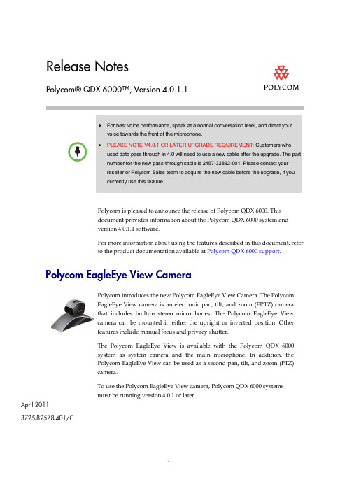
Release NotesPolycom® QDX 6000™, Version 4.0.1.1• For best voice performance, speak at a normal conversation level, and direct yourvoice towards the front of the microphone.• PLEASE NOTE V4.0.1 OR LATER UPGRADE REQUIREMENT: Customers whoused data pass through in 4.0 will need to use a new cable after the upgrade. The partnumber for the new pass-through cable is 2457-32892-001. Please contact yourreseller or Polycom Sales team to acquire the new cable before the upgrade, if youcurrently use this feature.Polycom is pleased to announce the release of Polycom QDX 6000. Thisdocument provides information about the Polycom QDX 6000 system andversion 4.0.1.1 software.For more information about using the features described in this document, referto the product documentation available at Polycom QDX 6000 support .Polycom EagleEye View CameraPolycom introduces the new Polycom EagleEye View Camera. The PolycomEagleEye View camera is an electronic pan, tilt, and zoom (EPTZ) camerathat includes built-in stereo microphones. The Polycom EagleEye Viewcamera can be mounted in either the upright or inverted position. Otherfeatures include manual focus and privacy shutter.The Polycom EagleEye View is available with the Polycom QDX 6000system as system camera and the main microphone. In addition, thePolycom EagleEye View can be used as a second pan, tilt, and zoom (PTZ)camera.To use the Polycom EagleEye View camera, Polycom QDX 6000 systemsmust be running version 4.0.1 or later.Polycom EagleEye View Camera as the main PTZ control cameraPolycom EagleEye View Camera as the second PTZ control cameraNote: The part number of the serial cable for second PTZ camera control is2457-32891-001.New CablesThe Polycom QDX 6000 has the following additional cables.CablesDescriptionPN: 2457-32890-001 An EagleEye View camera cable. One end of this cable is an HDCI connector to theEagleEye View camera, the other end breaks out to the following connectors,▪ A DB-9 male connector to QDX serial port for camera control. ▪An S-Video connector to QDX camera input. ▪ Two RJ-9 connectors to QDX MIC inputs.PN: 2457-32892-001 A DB-9, male-female, serial cable for transparent data pass-through;Cables DescriptionPN: 2457-32891-001A DB-9, female-female, serial cable for second camera PTZ control.What’s New in Version 4.0.1.1The version 4.0.1.1 software includes the features and functionality of version4.0.1. Systems running version 4.0.1.1 software can use the Polycom EagleEyecamera as the main camera or as a second camera.Using the Polycom EagleEye CameraThe camera will be detected automatically once the system starts up.The Polycom EagleEye camera does not support hot- plugged in with QDX 6000, whichmeans if the Polycom EagleEye camera is unplugged during usage, you need to detectthe camera manually before using it again.To detect the Polycom EagleEye camera manually:1.Connect the Polycom EagleEye camera to the Main/ Document camerainput.2.Press and set Main/Document camera as video source.3.Go to System > Admin Settings > General Settings > Serial Ports.4.Set RS-232 Mode to Camera PTZ.5.Click Detect Camera.What’s New in Version 4.0.1The version 4.0.1 software includes the features and functionality of version4.0.0, with the following additions.MulticastYou can configure the QDX 6000 system to allow users to stream audio andvideo from one to many viewers. Viewers watch the conference from thesystem's web interface. You can start streaming only when QDX 6000 is in a call.Points to note about streaming:•To send a stream across a subnet, multicasting must be enabled on thenetwork or you can unicast to a particular IP address, which will forwardthe stream to that IP address.•The number of viewers is limited only by your network topology.To configure the QDX system for a streaming call:1 Go to System > Admin Settings > Network > IP > Multicast.2 Configure these settings:3 Go to System > Admin Settings > General Settings > Security > SecuritySettings > >.4 Enable Allow Video Display on Web .To stream a conference:1 Go to System > Admin Settings > Network > IP > Multicast , select theEnable Multicast option.2In the browser address line, enter the system’s IP address, for example, http:// 10.11.12.13, to go to the system’s web interface. Go to Admin Settings >General Settings > Security , set the Remote Access password and theMeeting password.3 Place the video call to other participants.> ).To stop streaming a conference:1Go to System > Admin Settings > Network > IP > Multicast . 2Clear the Enable Multicast selection.To view a streamed conference:1 On a computer running Windows XP or Windows Vista operating system,open an Internet Explorer 6.x, 7.x, or 8.x.2 In the browser address line, enter http://xxx.xxx.xxx.xxx/m_multicast.htm,where “ xxx.xxx.xxx.xxx” is the QDX 6000 system's IP address.3 In the prompted window, enter the user name "meeting" and the meetingpassword set on your QDX 6000 system.The stream starts automatically.To stop viewing the streamed conference:>> Close the web browser.This stops the stream but does not end the call.Camera Control for the Second PTZ CameraQDX 6000 V4.0.1 supports camera control for the second PTZ camera.To connect a second PTZ camera to the QDX 6000 system:1 Connect a second camera supporting PTZ, such as Polycom EagleEye Viewcamera, to DOC camera input and serial control. The Polycom female-maleconvert cable (labeled as “2ND CAMERA”) MUST be used to connect thesecond camera serial port to the QDX serial control port.Note: The part number of the serial cable for second PTZ camera control is2457-32891-001. This cable can be easily recognized by the “2ND CAMERA”label on one end of the cable.2 Set Doc camera as video source.3 Go to System > Admin Settings > General Settings > Serial Ports, and setRS-232 Mode to Camera PTZ. Then click Detect Camera to detect thecamera manually.Notes:•IR signal cannot be received through the second PTZ camera.•PTZ speed setting is not available for this camera. OthersCorrected Issues in 4.0.1.1The following table lists corrected issues in version 4.0.1.1.Corrected Issues in 4.0.1The following table lists corrected issues in version 4.0.1.Known limitationsThe following table lists the known limitations for the version 4.0.1.1 release. If aworkaround is available, it is noted in the table.InteroperabilityPolycom QDX 6000 systems are tested extensively with a wide range ofproducts. The following list is not a complete inventory of compatibleequipment; it simply indicates the products that have been tested forcompatibility with the 4.0.1.1 release.Video conferencing systems use a variety of algorithms to compress audio andvideo. In a call between two systems, each end transmits audio and video usingalgorithms supported by the other end. In some cases, a system may transmit adifferent algorithm than it receives. This process occurs because each systemindependently selects the optimum algorithms for a particular call, and differentproducts may make different selections. This process should not affect thequality of the call.Copyright Information© 2010 Polycom, Inc. All rights reserved. No part of this document may bereproduced or transmitted in any form or by any means, electronic ormechanical, for any purpose, without the express written permission of Polycom,Inc. Polycom, Inc. retains title to, and ownership of, all proprietary rights withrespect to the software contained within its products. The software is protectedby United States copyright laws and international treaty provision. License IssuesOpenSSL LicenseCopyright (c) 1998-2007 The OpenSSL Project. All rights reserved.Redistribution and use in source and binary forms, with or without modification,are permitted provided that the following conditions are met:1 Redistributions of source code must retain the above copyright notice, thislist of conditions and the following disclaimer.2 Redistributions in binary form must reproduce the above copyright notice,this list of conditions and the following disclaimer in the documentationand/or other materials provided with the distribution.3 All advertising materials mentioning features or use of this software mustdisplay the following acknowledgment:"This product includes software developed by the OpenSSL Project for usein the OpenSSL Toolkit. (/)"4 The names "OpenSSL Toolkit" and "OpenSSL Project" must not be used toendorse or promote products derived from this software without priorwritten permission. For written permission, please contact************************.5 roducts derived from this software may not be called "OpenSSL" nor may"OpenSSL" appear in their names without prior written permission of theOpenSSL Project.6 Redistributions of any form whatsoever must retain the followingacknowledgment:"This product includes software developed by the OpenSSL Project for usein the OpenSSL Toolkit (/)"THIS SOFTWARE IS PROVIDED BY THE OpenSSL PROJECT ``AS IS''AND ANY EXPRESSED OR IMPLIED WARRANTIES, INCLUDING, BUTNOT LIMITED TO, THE IMPLIED WARRANTIES OFMERCHANTABILITY AND FITNESS FOR A PARTICULAR PURPOSEARE DISCLAIMED. IN NO EVENT SHALL THE OpenSSL PROJECT ORITS CONTRIBUTORS BE LIABLE FOR ANY DIRECT, INDIRECT,INCIDENTAL, SPECIAL, EXEMPLARY, OR CONSEQUENTIALDAMAGES (INCLUDING, BUT NOT LIMITED TO, PROCUREMENT OF SUBSTITUTE GOODS OR SERVICES; LOSS OF USE, DATA, OR PROFITS;OR BUSINESS INTERRUPTION) HOWEVER CAUSED AND ON ANYTHEORY OF LIABILITY, WHETHER IN CONTRACT, STRICT LIABILITY, OR TORT (INCLUDING NEGLIGENCE OR OTHERWISE) ARISING INANY WAY OUT OF THE USE OF THIS SOFTWARE, EVEN IF ADVISED OF THE POSSIBILITY OF SUCH DAMAGE.This product includes cryptographic software written by Eric Young(*****************).ThisproductincludessoftwarewrittenbyTimHudson(*****************).Original SSLeay LicenseCopyright(C)1995-1998EricYoung(*****************)Allrightsreserved. This package is an SSL implementation written by Eric Young(*****************).Theimplementationwaswrittensoastoconformwith Netscape’s SSL.This library is free for commercial and non-commercial use as long as the following conditions are adhered to. The following conditions apply to all code found in this distribution, be it the RC4, RSA, lhash, DES, etc., code; not just the SSL code. The SSL documentation included with this distribution is covered by the same copyright terms except that the holder is Tim Hudson(*****************).Copyright remains Eric Young's, and as such any Copyright notices in the code are not to be removed.If this package is used in a product, Eric Young should be given attribution as the author of the parts of the library used. This can be in the form of a textual message at program startup or in documentation (online or textual) provided with the package.Redistribution and use in source and binary forms, with or without modification, are permitted provided that the following conditions are met:1 Redistributions of source code must retain the copyright notice, this list ofconditions and the following disclaimer.2 Redistributions in binary form must reproduce the above copyright notice,this list of conditions and the following disclaimer in the documentationand/or other materials provided with the distribution.3 All advertising materials mentioning features or use of this software mustdisplay the following acknowledgement:"This product includes cryptographic software written by Eric Young(*****************)"The word 'cryptographic' can be left out if the routines from the librarybeing used are not cryptographic related :-).4 If you include any Windows specific code (or a derivative thereof) from theapps directory (application code) you must include an acknowledgement:"This product includes software written by Tim Hudson(*****************)"THIS SOFTWARE IS PROVIDED BY ERIC YOUNG ``AS IS'' AND ANYEXPRESS OR IMPLIED WARRANTIES, INCLUDING, BUT NOT LIMITEDTO, THE IMPLIED WARRANTIES OF MERCHANTABILITY ANDFITNESS FOR A PARTICULAR PURPOSE ARE DISCLAIMED. IN NOEVENT SHALL THE AUTHOR OR CONTRIBUTORS BE LIABLE FORANY DIRECT, INDIRECT, INCIDENTAL, SPECIAL, EXEMPLARY, ORCONSEQUENTIAL DAMAGES (INCLUDING, BUT NOT LIMITED TO,PROCUREMENT OF SUBSTITUTE GOODS OR SERVICES; LOSS OF USE,DATA, OR PROFITS; OR BUSINESS INTERRUPTION) HOWEVERCAUSED AND ON ANY THEORY OF LIABILITY, WHETHER INCONTRACT, STRICT LIABILITY, OR TORT (INCLUDING NEGLIGENCEOR OTHERWISE) ARISING IN ANY WAY OUT OF THE USE OF THISSOFTWARE, EVEN IF ADVISED OF THE POSSIBILITY OF SUCHDAMAGE.The license and distribution terms for any publically available version orderivative of this code cannot be changed. I.e. this code cannot simply becopied and put under another distribution license [including the GNUPublic License.]DisclaimerThis software is provided 'as is' with no explicit or implied warranties in respectof its properties, including, but not limited to, correctness and fitness forpurpose.Trademark Information© 2011, Polycom, Inc. All rights reserved. POLYCOM®, the Polycom "Triangles"logo and the names and marks associated with Polycom's products aretrademarks and/or service marks of Polycom, Inc. and are registered and/orcommon law marks in the United States and various other countries. All othertrademarks are property of their respective owners. No portion hereof may bereproduced or transmitted in any form or by any means, for any purpose otherthan the recipient's personal use, without the express written permission ofPolycom.。
E-Vision系列 WXGA 6000, WXGA 7000 XGA 6000, XGA 7000

E-Vision系列WXGA 6000, WXGA 7000 XGA 6000, XGA 7000高亮度数字投影机DP (Digital Projection)Digital Projection 公司总部,地址:Greenside Way, Middleton, Manchester M24 1XX, UK. 英国注册号:2207264电话:+44 (0) 161 947 3300传真:+44 (0) 161 684 7674电子邮箱:****************************.uk网址:Digital Projection中国办事处北京中国北京市朝阳区小营路19号财富嘉园C座1202室电话:(86*************传真:(86*************上海中国上海市中山西路1800号兆丰环球大厦4楼B座电话:(86*************传真:(86*************广州中国广州市河区体育西路101号维多利广场A座2105室电话:(86*************传真:(86*************电子邮箱:************************.cn网址:重要信息目录用户手册中指示标识 (3)合格声明 (4)电子和物理规格 (5)注意事项 (5)安装指示 (6)操作指示 (7)遵循国际标准 (7)RF interference (7)噪音 (7)欧洲废弃电气和电子设备(WEEE)指令 (7)用户手册包括投影机操作、连接、安装的完整信息,详细内容参看CD光盘。
指示标志警告用电警告:如果不严格按照说明操作会出现电击危险。
警告:如果不严格按照说明操作会出现身心伤害或损害到机器。
注意注意:您应该阅读的重要信息。
未经通知规格不得变更。
合格声明认证指令2004/108EC电磁兼容性指令.2006/95/EC低压设备指令.认证产品大屏幕数字投影机此认证首次应用于:E-Vision WXGA 600 2011年12月E-Vision WXGA 7000 2011年12月E-Vision XGA 600 2011年12月E-Vision XGA 7000 2011年12月认证详情产品不仅符合以上EU指令,还符合以下标准:EN 55022: 2006+ A1:2007 -信息技术设备无线电干扰特性限值和测量方法;EN 55024: 1998+ A1:2001+ A2:2003 -信息技术设备抗干扰特性限值和测量方法;EN 60950-1: 2006/A11:2009 -包括电子商务设备在内的信息技术设备安全的详尽说明。
国祥.厂家使用说明书(适用于模块机)..V200A0
C
C
0 #、1 # . . .对 应S R 1设 置 的 模 块 地 址0 ~ F
如设 置 为5个 模块, 则应 有0#~4#,共5块LY514A相 连
2
DM602A+LY514A模块机组控制器
4 显示器
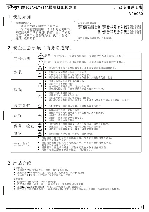
4-1 DM602A安装及尺寸
11 9 . 5 0
21.5
厂家使用说明书
( 单 位:mm)
O4 O4 O5
4-2 DM602A面板介绍
z 对应数字0~7的按键,可用于设置密码 z 如果密码中存在数字8或数字9: z 数字8用0代替;数字9用1代替。 z 启动、复位、设定键无对应数字
0_时钟键:用于设定时钟 1_定时键:用于设定定时 设定键:z 用于确定被修改值 z 处于主界面时,按此键进入温度设定
AUTO AUTO
复位 取消设定 设定 保存设定
返回运行主界面
T.SET. C
复位 取消设定 设定 保存设定
返回运行主界面
运行主界面
模式
T.
№
C
模式
T.SET. C
安装
接线
设定参数 运行 保养、检查 其它 责任声明
z 请安装在金属等不易燃烧的板上,并牢固安装以免因震动而跌落;
! z 受损或缺少部件的控制器,切勿安装; z 不要暴露在阳光直射、强气流及水雾中; z 不要暴露在腐蚀性的或被污染的气体中,如硫化物气体、盐雾。
z 请确认电源输入是否处于OFF状态。 z 请电气工作人员接线作业。 z 输入端为无源开关信号,切勿接入电源。 z 请增加系统级保护,避免电脑控制器失效而产生危险。
注 : 关于 接插 件 参考『LY514A介 绍 』
线规(28-16AWG) 线规(24-12AWG)