双面自动输稿器维修手册(英文版)
美能达复印机维修模式中英文对照概要

美能达维修模式中英文对照Service Mode(维修模式一、SERVICE'S CHOICE(技术维修选择1、SHIPMENT DESTINATION (市场地区2、MAINTENANCE COUNTER (保养计数器3、IU LIFE STOP MODE (IU 寿命终止模式4、ID ADJUST (ID 调整5、VG ADJUST (VG 调整6、FUSER TEMP. Ad (PLAIN(定影温度调整(普通纸7、FUSER TEMP. Ad (THICK(定影温度调整(厚纸8、FUSER TEMP. Ad (OHP(定影温度调整(OHP9、LEADING EDGE ERAGE (前边缘消除10、T RAILING EDGE ERAGE (后边缘消除11、V ERTICAL EDGE ERAGE (上下边缘消除12、L OOP ADJUST (TRAY1(波幅调整(第 1 纸盒13、L OOP ADJUST (TRAY2 TO TRAY5*(波幅调整(第2纸盒到第5纸盒14、LOOP ADJUST (DUPLEX(波幅调整(双面15、LOOP ADJUST (BYPASS(波幅调整(手送进纸16、FLS PAPER SIZE (FLS 纸张尺寸17、C CD APS SIZE (CCD APS 尺寸18、G DI TIMEOUT (GDI 超时二、ADJUST (调整1、PRN MAIN REGIST (打印主对位2、PRN SUB REGIST (打印次对位3、CCD MAIN ZOOM (CCD 主缩放4、CCD SUB ZOOM (CCD 次缩放5、CCD MAIN REGIST (CCD 主对位6、CCD SUB REGIST (CCD 次对位7、ADF SUB ZOOM (ADF 次缩放8、ADF MAIN REGIST (ADF 主对位9、ADF SUB REGIST1 (ADF 次对位 110、ADF SUB REGIST2 (ADF 次对位 211、A DF REG. LOOP 1 (ADF 对位波幅 112、A DF REG. LOOP 2 (ADF 对位波幅 213、A TDC GAIN (A TDC 增益14、MODEL SETTING (模式设定COUNTER (计数器1、TOTAL COUNTER (总计数器2、SIZE COUNTER (尺寸计数器3、PM COUNTER (PM 计数器4、MAINTENANCE COUNTER (保养计数器5、SUPPLIES LIFE COUNT.(使用寿命计数6、APPLICA TION COUNTER (应用计数器7、SCAN COUNTER (扫描计数器9、MISFEED COUNTER (卡纸计数器10、TROUBLE COUNTER (故障计数器四、DISPLAY (显示1、TONER DENSITY LEVEL (碳粉浓度水平2、PROCESS CONTROL (过程控希 93、MAIN F/W VER.(主机固件版本4、ENGINE F/W VER.(引擎固件版本5、PCL F/W VER.* (PCL 固件版本 *& NIC F/W VER.* (网卡固件版本*7、ADF F/W VER.* (ADF 固件版本*8、MAIN RAM SIZE (主内存大小9、PCL RAM SIZE* (PCL 内存大小 *10、SERIAL NO.(序列号11、CUSTOMER ID (用户识别码五、F UNCTION (功能1、PAPER FEED TEST (送纸测试2、PROCESS CHECK 过程检查3、A TDC AUTO ADJUST (A TDC 自动调整4、PRINT TEST PATTERN (打印测试图案5、ADF FEED TEST (ADF 输稿测试6、COPY ADF GLASS AREA(复印 ADF 玻璃区域7、CCD MOVE TO HOME (CCD 移至U原位8、SCAN TEST (扫描测试9、ADF WIDTH ADJ. (MAX*(ADF 宽度调整(最大 * 10、ADF WIDTH ADJ.(MIN*(ADF 宽度调整(最小 * 11、ADF SENSOR ADJUST* (ADF 感应器调整 *六、A DMIN. REGISTRATION (管理员注册七、F IXED ZOOM CHANGE(固定缩放修改1、REDUCTION2 (缩小 22、REDUCTION1 (缩小 13、EXPANSION1 (放大 14、EXPANSION2 (放大 2七、FIXED ZOOM CHANGE(固定缩放修改八、FACTORY TEST(出厂测试1、PANEL BUZZER TEST (面板蜂鸣器测试2、RAM TEST (RAM 测试九、C LEAR DATA (清除数据1、MEMORY CLEAR (清除内存数据2、PM COUNTER (PM 计数器3、MAINTENANCE COUNTER (保养计数器4、SUPPLIES LIFE COUNT.(使用寿命计数5、APPLICA TION COUNTER (应用计数器6、SCAN COUNTER (扫描计数器8、MISFEED COUNTER (卡纸计数器9、TROUBLE COUNTER (故障计数器10、ADF BACKUP CLEAR*(ADF 备份数据清除* 十、SECURITY (安全性1、TOTAL COUNTER COUNT (总计数器计数2、SIZE COUNTER COUNT (尺寸计数器计数3、PLUG-IN COUNTER COPY(接插式计数器复印4、MACHINE COUNTER (机器计数器。
AR-M276维修手册

AR-FX7 传真扩展组件
AR-NS2 网络 扫描仪扩展组件
AR-SM5 256MB 扩展内存条
AR-SM6 512MB 扩展内存条
AR-MM9 8MB 传真内存
AR-M276 配 置 1 – 1
C. 选购件组合列表
○ : 可安装
× : 不可用
相关部分
选购件 名称
型号
自动输稿器
双面自动输稿器
AR-RP7
1. 安 装 ................................................................ 4 - 1 2. 卸除保护材料和固定螺钉 ................................... 4 - 3 3. 固定销的卸除和保存 .......................................... 4 - 3 4. 显影盒安装......................................................... 4 - 4 5. 墨粉盒安装......................................................... 4 - 5 6. 墨粉浓度传感器水平调整 ................................... 4 - 5 7. 纸盒的纸张尺寸设定 .......................................... 4 - 5 8. 选购件安装......................................................... 4 - 7
进纸系统
2 × 500 页进纸组件 AR-D22
出纸系统
DP23S维修手册
一体机培训指导教材第一章:一体机的安装1、安装位置注意事项◆安装环境◆避免阳光直射◆避免过高或过低的温度◆避免灰尘◆放置平稳◆使用机器时避免歪斜2、安装过程注意事项◆使用机器说明中所要求的电源电压◆使用机器专用的电源线◆不要与其他设备共用一根电源3、维护、检查、维修的注意事项◆一定要拔下电源线后再开始维护、维修◆检查时小心切刀部分的刀片,以免划伤手◆点动滚筒时,不要将手伸进机器第二章:一体机特性一、特性1印刷幅面A3/B4(DP-23S)7 丰富的常用功能DP-2930/DP-2940:A3(290*423mm) DP-2530/DP-2540:B4(250*355mm)①简便的原稿缩除了等倍印刷外,放大和缩小还各提供了 三档自动设定。
此外,94%可用于各档。
《 A/B 尺寸模式 》◆缩放设置(70,81,86,115,122,141%)◆100%印刷◆50—500%自由缩放141%[A4→A3 , B5→B4] 放大 121%[A4→B4 , A5→B5]115%[B4→A3 , B5→A4]* DP-2530 DP-2540的最大印刷负面为B42高速制版第一张印刷品完成(A4原稿) DP-2940/DP-2540:21秒 DP-2930/DP-2530:27秒4排纸调整◆缩放设置(64,74,77,121,129,141%) ◆100%印刷◆50—500%自由缩放141%放大 129%[LTR →LDG ]121%[LGL →LDG ]排纸调整架使厚纸与薄纸都能顺畅 的排出。
5 高效灯管采用长寿命、高亮度氙气弧光灯 管照射原稿。
因为灯管的亮度不 受温度变化的影响,所以印刷品 的质量得到极大的提高。
6 操作简便 ②自检功能本纪设有自检系统,当耗材需更换时,与之 相关的设在控制面板上的指示灯将会闪烁, 以提醒用户更换耗材。
③书本中心和边缘阴影消除书本或原稿的中心和边缘的阴影可被消除。
通过使用小盖板下的非常用键使操作 简单化。
5200l英文菜单说明

RTT MIN= 0 (最小 RTT= 0 )
RTT MAX= 0 (最大 RTT= 0 )
RTT AVERAGE= 0 (平均 RTT= 0 )
PING IN PROGRESS= NO (程序中 PING = 否)
( continued) (待续)
FORM LENGTH= 64 (表格长度 =64 )
TRANSPARENCY= LOW3 (投影胶片 = 低温 3 )
WAKE TIME (唤醒时间)
ORIENTATION = PORTRAIT (方向 = 纵向)
PREPUNCHED= NORMAL (预打孔纸 = 正常)
MONDAY= 21:37 (周一 =21 : 37 )
RESOLUTION= FASTRES 1200 (分辨率 = FASTRES 1200 )
RET= MEDIUM ( RET= 中)
ECONOMODE= OFF (节省碳粉模式 = 关闭)
TONER DENSITY= 3 (碳粉浓度 = 3 )
CREATE CLEANING PAGE (创建清洁页)
UNIT OF MEASURE = MILLINUETERS (度量单位 = 毫米)
X1 SHIFT= 0 ( X1 偏移 = 0 )
TIME= 11 : 49 (时间 =11 : 49 )
X DIMENSION = 312 MILLIMETERS ( X 尺寸 =312 毫米)
X2 SHIFT= 0 ( X2 偏移 = 0 )
SOURCE= TRAY 2 (来源 = 纸盘 2 )
DUPLEX= OFF (双面打印 = 关闭)
COPIES= 1 (份数)
维修手册英文版
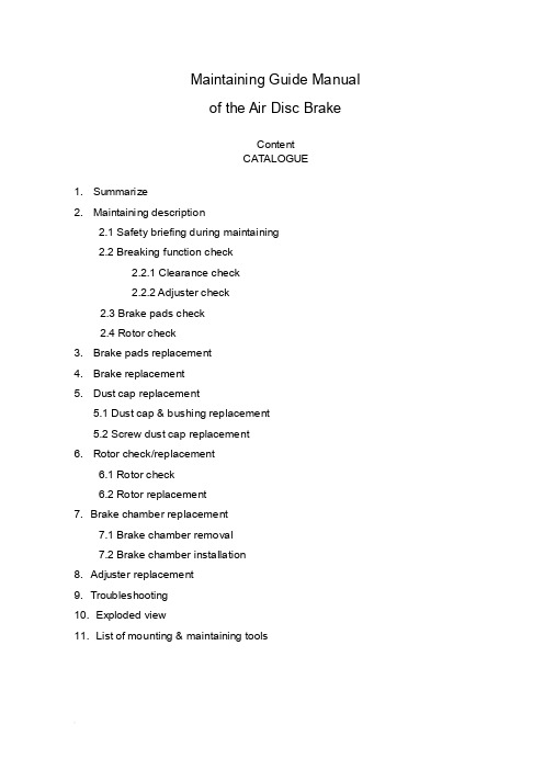
Maintaining Guide Manualof the Air Disc BrakeContentCATALOGUE1. Summarize2. Maintaining description2.1 Safety briefing during maintaining2.2 Breaking function check2.2.1 Clearance check2.2.2 Adjuster check2.3 Brake pads check2.4 Rotor check3. Brake pads replacement4. Brake replacement5. Dust cap replacement5.1 Dust cap & bushing replacement5.2 Screw dust cap replacement6. Rotor check/replacement6.1 Rotor check6.2 Rotor replacement7. Brake chamber replacement7.1 Brake chamber removal7.2 Brake chamber installation8. Adjuster replacement9. Troubleshooting10. Exploded view11. List of mounting & maintaining toolsBrief introduction of YOUFINYOUFIN was established on May 20th, 1998. It is a Sino-Foreign joint-venture enterprise registered in Wuhan Economic and T echnological Development Zone with multi-investors among which private investors dominate. It is a professional company engaged in manufacturing disc brakes and serving the principal automobile manufacturers by providing modularized supply. The main prod ucts cover hydraulic disc brakes and air disk brakes in close to thirty sizes.YOUFIN developed the air disc brake autonomously and patented the product. So far we are the only manufacturer in China that can mass produce air discs to be used in long distance coaches and inner city buses. It is evaluated that the quality of our products is close to the advanced international level in field use. The product development is part of the National T orch Plan and is also sponsored by the Small and Medium-sized Enterprise T echnical Innovation Foundation of Chinese Ministry of S&T.Our Air Disc Brake products are on an absolute leading position in China and the same international level as far as the key technology is concerned.1. SummarizeYOUFIN Air Disc Brake has four sizes (16’’, 17.5’’19.5’’, 22.5’’). It can satisfy different vehicles. The brakes have compact structure; automatically wear compensation and can easily changing the brake pad.2. Maintaining descriptionSafety briefing during maintainingIt’s most important to ensure safety driving and breaking by goodcharacteristics of the brake.Observe brake pad and rotor wear limits. When they warned already to assigned smallest thickness, it need replace immediately, otherwise, it may cause the accident. The pads scorches, grinds or greases must replace immediately.Every pad on each bridge must replace at the same time.When services the brake, the vehicle must park in smooth gound and the wheel withstand with the block/ stone prevent rolls.Note:●Must guarantee it does not occur with careless brake. When replace brakepad don’t make the brake, otherwise, it will hurts the body!●Do not use the compressed air or other cleaning up equipment clean thebrake, in order to avoid injures the body.●Be sure your hands and fingers place outside the caliper, in order to avoidinjures the body.●When moves and installs the brake should have some assistance, avoids ittoo heavy to hurts the body.●When take off the brake to make maintenance, it must fix on the clamp withhigh strength bolt, in order to avoid hurts the body.●Only allowed genuine YOUFIN kits and pads permitted by YOUFIN. Duringthe first 50 miles driving after new pad replacement, should avoid promptlybrake and brake at a long distance, Prevent overhigh temperature.●Allowed genuine YOUFIN kits and brake pads permitted by YOUFIN.●Only can use the recommendation kits in service. Screws the bolt/nutaccording to the request moment of force.Brake Function checkClearance checkProcess:●T ake off the hexagon bolt (39), loosen the pad retainer (38).●Remove pad retainer (38) from caliper.●Remove 3pcs of pad clip (37).●Move the cable (40) to the side.●Push the caliper towards the wheel and check the clearance with tune-upgauge.0.5mm ≤ clearance ≤ 1.2mmNote: Insert tune-up gauge between the caliper (1) and the brake pad (35). Should check the adjuster while the clearance is out of standard.Adjuster checkProcess:●Remove the rubber cap (12).●Turn hexagon head (22) clockwise by wrench to ensure clearance larger than3mm. (Or remove the brake pad and the push board)Note:a. Need enough room (3mm<clearance) for turn adjuster preventing un-fit.b. Never force to adjust the hexagon head (22) and/or the adjuster!Push the pressure arm 5 times in small increments and observe the hexagon head (22). While the adjuster is in good condition, hexagon head (22) must rotate clockwise.c. As the regulated quantity increase, rotation angle decreases.If the adjuster hexagon head (22):a) Not running at allb) Only running at first pushc) Running, but stopped in the middleWhile considers adjuster failed. Y ou should replace the brake on the basis of section 4 or change the adjuster in accordance with section 8.●Keep the clearances at 1mm (section 3) after adjuster check is finished.●Reinstall the rubber cap (12).Brake pads wearing check●Scorches, grinds and greased brake pad must replaces immediately.●Brake pads at the same bridge must replace at the same time.●Brake pad and pad clip must replace at the same time.Rotor checkProcess:●Remove the brake pad according to section 3.●T est thickness of the rotor.Note: Observe the brake pads and the rotor attrition situation. Excessive attrition of the rotor and the brake pads will reduce their potency and causes the brake fail!CAUTION: Rotors on the same bridge must replace at the same time. Single side rotor replacement is unacceptable. Recommend installs new brake pads whilereplace the new rotors.Rotor Dimension limitsRotor jumpiness (↗) check:2.4.1 Process:●Installs division indicator on the bracket (dial guage).●Measure jumpiness (↗) through turns the wheel. Jumpiness (↗) should lessthan 0.15.●Replaces the rotor to satisfy the request of section 6.●Modified brake pad should fulfil the specific requirements in section 3.2.4.2 Rotor test:At each change of Pads check the Rotor for grooves and cracks.The diagram at the right shows possible conditions of the surface.A = Small cracks spread over the surface are allowedB = Cracks less than 0.02in. (0.5mm) wide, running in a Radial direction, are allowedC = Grooves (circumferential) less than 0.06in. (1.5mm) wide are allowedD = Cracks in the vanes are not allowed and the Rotor MUST BE REPLACED.a = Pad contact area3. Brake Pad replacementNote: Do not use the pipe spanner/ board die! Keep your hands and fingers outside the caliper avoid the hurts of body!Brake Pad dismantle process:●T ake off hexagon bolt (39) from the Pad Retainer with spanner.●Remove the pad retainer from caliper (1).●T ake off the pad clip (37), which is above the pads (35,36) and push board (19).●Remove the sensor on brake pad.●T ake off the push board (19) & the brake pads (35,36).●Adjust hexagon head to make tappet back to the initial position.●Clean the pad groove & push board and anchor surface with brush.Note: Don’t hurt the dust cap (5 & 10). Be sure of no grease on installation surface!●Check the adjuster on the basis of section 2.2.2.Note: Fix the key while checking & turning the adjuster cap to avoid screw rotate.●Check the rotor according to section 2.4.3.2 Brake pad installing process:●Need enough room between the caliper & the rotor to insert brake pad.●Insert push board (19) at the place the caliper combine with the adjust screw.Note: Push board must on the bracket supporting surface. Adjust screw pin must in groove. Otherwise it will do harm to Adjuster mechanism. Ensure the dust cap untwisted by rotate the adjust screw.●Insert the cable sensor to pad groove. Fix cable on bearing (40).Note: The sensor contactor must face the brake disc and installs at the correctposition. Attention the wire trend to prevents the friction.●Insert new pad (36) at side of the push board.●Push caliper toward the wheel until the pad touch the rotor.Insert the brake padat wheel side.Note: Don’t adjust hexagon head violently.Note: Turn the adjuster counter-clockwise to decrease the clearance between pads.Don’t install the retainer before adjustment.Note: Check the rubber cap (12), be sure it is correctly seated.4. Brake replacementNote: Don’t use pipe wrench. Ensure your hands and fingers outside the caliperavoid hurt your body!Note: The Brake will supplies in assembly.CAUTION: The left brake and the right brake cannot exchange. Arrow direction on the brake is same as the forward direction of the wheel.4.1 Brake removal process:●Remove brake pad (see Section 3).●Release nut on the caliper, take of brake chamber.●Remove brake assessment from the bridge.●Check brake pad on the basis of section 2.3.●Check rotor on the basis of section 2.4.4.2 Brake installing process:●Install the new brake over rotor on the bridge. Screwed bolt with the spanner.Note: The right install order of the bolt is screwed both side symmetry.●T ake down the flange protection cap on the brake chamber.Note:Air chamber installment position. Open the scupper faces the ground, and stops other mouths.●Install brake pad and push board on the basis of section 3.●Install the air chamber and tighten with spanner.●Adjust the clearance.5. Guide Pin dust cap replacementNote: Do not use the pipe spanner/ board die! Keep your hand & finger outside the caliper, in order to avoid injuries.Note: When replaces all dust cap of guide bushing, section 5.1 & 5.2 should unify to avoids repetitive work. Single bushing replacement according to 5.1 and 5.2 corresponding work orders.5.1. Dust cap & bushing replacement●T ake off the brake pad according to section 3.●Loosen the chamber bolt and remove the brake chamber from caliper.●Remove the caliper assessment from bridge.●T ake off the steel cap (11) from guide bushing (8 & 9) by suitable tools.Dismantle caliper (1) from the bracket (2).Note: Don’t hurt the hole, the lid while open the steel cap with tools.●Loosen the bolt (6 & 7); separate the caliper (1) from the bracket (2).Note: When caliper moves, it may hurt body.●Cleaning up the bracket bonding plane●Take off the guide pin (8&9) on caliper (1). Then remove the dust cap (5).●Presses out bushing 4 with mandril from caliper1.●Cleans up the guide pin hole of caliper.Installing process:●Long guide pin hole must press in two new bushings. Short guide pin holepress in one.●Guarantee the size in drawing.●Greases between them and the bushing●Install new dust cap in the guide pin hole.Note: Cleans up the guide pin hole and grease the edge of dust cap before install for easy installation. Ensure the dust cap installs steadily, without crease and inside the ring groove of the caliper.●Install long/short guide pin to each hole and dust cap upside set in guide pinring groove.●Put the caliper (1) on the bracket (2) and plug guide pin (8&9) in guide hole.●Plug new bolt (6&7) (long one for pin 8, short one for pin 9) and screwed onbracket (2) with spanner.Note: Assembly must be careful, don’t damage the dust cap (5). First, screws bolt on long pin (8), and then screws bolt on short pin (9).When service maintenance, remove the guide pin (8&9) and replace by new bolt (6&7)!●Move the caliper on guide pin (8,9) forward and backward to check whether thecaliper can move freely.●Put on new copper cap on caliper (1) hole and push it in with correct kits. Note: Avoids the hurts of surface.●Raising the guide pin dust cap (5) carefully for cancel the air pressure.●Install brake across the rotor on bridge. Screwed bolt with the spanner.Note: Correct install process of the hexagon bolt.●Install brake pads and adjust clearance. Implemented section 3, notice theexplanation.●Cleaning the install flange on caliper and grease inside the pressure arm ballsocket before reinstall the brake chamber.●Install the brake chamber and screwed with spanner.Note: After the installation of brake chamber, the lowest chamber hole face theground must open, other mouths stop up.5.2. Screw dust cap replacementNote: If only replace the screw dust cap, does not need to remove the caliper andthe air chamber.Process:●Remove brake pad and push board according to section 3.●Push the caliper towards to brake chamber.●T ake off screw dust cap (10) from the ring groove on adjust screw (21).●T ake down from dust cap base with screwdriver.●Check screw thread.●Turning the adjust bolt for 30mm clockwise with the spanner.●Inspection thread corrosion and whether is damaged.●Turning it clockwise, feeling its lubrication and check the adjust screw thread.●Clean the base of caliper dust cap (10). (Arrow pointed)●Push new dust cap (10) on adjust screw. Install it on the base with kits. Observes itinstalls whether arrived.●Grease on the edge of dust cap (10) and install it on the base of adjust screw (21).Note: Guarantees the dust cap steadily in place and does not have the corrugation in the adjust screw ring groove.Installation process:●Install the brake pad and adjust the clearance (see Section 3).6. Rotor check/replacement6.1 Rotor check Check the rotor (Section 2.4) If the rotor reached the minimumthickness, it must be replaced.6.2 Rotor replacementNote: Generally recommend use new brake pad while install new/machined rotor.6.2.1 Uninstall the rotor:●R emove the brake pad. (see section 3)●T ake off the brake chamber. (see section 7)●T ake down brake from bridge. (see section 4)●T ake off the wheel and the rotor.(Refer to V ehicle Manufacture’srecommendations)6.2.2 Rotor installation:●I nstall the wheel and rotor. (refer to V ehicle Manufacture’s recommendations)●D egrease the rotor.●T urn the wheel and check the installed rotor (Section 2.4).●A djust ABS sensor refer to V ehicle Manufacture’s recommendations.●I nstall the brake (see Section 4).●I nsert pad (see Section 3).●I nstall brake chamber (see Section 7).7. Brake chamber replacementNote: Don’t use pipe wrench! Ensure your hands and fingers outside the caliperavoid hurts body!Note: Can only use the chamber assigned by the Vehicle Manufacture.7.1. Brake chamber removal:●Bleeds off the compressed air.●Remove the upper air pipe of brake chamber.●Remove the chamber from caliper.7.2. Brake chamber installation:Note: According to the brake installment position, only can open the scupperunderneath.●Cleans the sealing plane of the pressure are ball socket (arrow) and caliper beforethe brake chamber installation.●Screwed the chamber mounting nut alternately with spanner in torque ratingrequired by the air chamber supplier.●Connection the air pipe.Note: Never twist the braking line, place it originally avoid fiction with other sets.While exist air leak, finds the leakage and check the connection.●Function and performance examination.8. A djuster replacement8.1 A djuster removal●Remove brake pad (see Section 3).●Remove brake chamber (see Section 7).●T ake off brake (see Section 4).●T ake off upper bolt by hexagon wrench.●Remove adjuster and other parts in the caliper.Note: Don’t hurt the screw dust cap.8.2 A djuster installation●Grease inside the caliper.●Put the return spring (18) at each side.●Install the needle assembly and the adjuster.●Puts the washer and top head, screwed the bolt with spanner according to theopposite angle principle.Note: Guarantee the bolt tighted the moment of force.9. Troubleshooting11. List of mounting & maintaining toolsYOUFIN is in the process of logo replacement, new logo will put into practice gradually. It with the original logo is still the YOUFIN’s product. Final interpret right for the logo belongs to YOUFIN.。
佳能某型号打印机维修手册(英文版)
佳能某型号打印机维修手册(英文版)IntroductionThank you for choosing a Canon printer. This maintenance manual will provide you with information and guidance on how to properly maintain and troubleshoot your Canon printer. Regular maintenance and proper handling of the printer will help ensure that it operates at optimal performance and has a longer lifespan.Safety PrecautionsBefore performing any maintenance or troubleshooting procedures on the printer, it's important to keep the following safety precautions in mind:- Always turn off the printer and unplug it from the power source before performing any maintenance procedures.- Do not attempt to disassemble the printer unless you are a qualified technician.- Use only genuine Canon printer parts and supplies.- Keep the printer in a well-ventilated area and away from direct sunlight and heat sources.Maintenance ProceduresRegular maintenance of the printer is important to ensure its smooth operation. Here are some maintenance procedures that should be performed regularly:- Clean the printer: Use a soft lint-free cloth and mild detergent to clean the printer exterior and paper trays. Clean the print head and ink cartridges using the printer's cleaning feature.- Replace ink cartridges: When the ink levels are low, replace the ink cartridges with genuine Canon cartridges to ensure high-quality prints.- Check paper feed: Remove any paper jams and ensure that the paper feed is smooth and unrestricted.TroubleshootingIf your printer is not functioning properly, here are some troubleshooting steps you can take:- Check for paper jams: Open the printer cover and remove any jammed paper from the paper feed.- Check ink levels: If the prints are coming out faded or incomplete, check the ink levels and replace the cartridges if necessary.- Restart the printer: Turn off the printer, unplug it, and wait for a few minutes before plugging it back in and turning it on again.ConclusionProper maintenance and regular troubleshooting are essential for ensuring the smooth operation of your Canon printer. By following the guidelines provided in this manual, you can keep your printer in good working condition and avoid costly repairs. If you encounter any issues that cannot be resolved through these procedures, please contact a qualified technician for assistance.Certainly! Let's delve further into various aspects of Canon printer maintenance and troubleshooting, and provide more detailed information on how to keep your Canon printer in optimal working condition.1. Printer Cleaning and MaintenanceRegular cleaning of your Canon printer is crucial for maintaining its performance and extending its lifespan. Here's a more in-depth look at the steps involved in cleaning and maintaining your printer:a. Cleaning the Exterior: Use a soft, lint-free cloth slightly dampened with water to wipe down the exterior of the printer. Avoid using harsh chemicals or abrasives, as they may damage the printer's surface.b. Cleaning the Paper Trays: Remove all paper from the trays and wipe them with a dry cloth to remove any dust or debris. Check for any paper remnants that may be stuck in the trays and remove them carefully.c. Cleaning the Print Head: The print head is a critical component of the printer that can get clogged with dried ink. Most Canon printers have a built-in function to clean the print head. Refer to your printer's manual to locate and perform the print head cleaning process.d. Inspecting for Wear and Tear: Periodically check for any signs of wear or damage to the printer, such as frayed cables, loose parts, or worn-out rollers. Address any issues promptly to prevent further damage.2. Ink Cartridge ReplacementWhen the ink levels in your Canon printer are low, it's essential to replace the ink cartridges with genuine Canon cartridges. Using non-genuine or refilled cartridges can compromise print quality and potentially damage the printer. Here's a step-by-step guide on how to replace ink cartridges in your Canon printer:a. Turn off the printer and unplug it from the power source.b. Open the printer cover to access the ink cartridge compartment.c. Carefully remove the empty ink cartridge by gently pressing down on it and then pulling it out from its slot.d. Take the new genuine Canon ink cartridge out of its packaging and remove the protective tape.e. Insert the new ink cartridge into the appropriate slot, ensuring it is securely in place.f. Close the printer cover and plug the printer back in.After replacing the ink cartridges, the printer may perform an ink charging process to prepare the new cartridges for printing. Follow any on-screen instructions or notifications to complete this process.3. Paper Feed and HandlingSmooth paper feed is essential for avoiding paper jams and ensuring high-quality prints. Here are some tips for maintaining proper paper feed in your Canon printer:a. Use High-Quality Paper: Ensure that you are using high-quality, compatible paper that meets the specifications recommended by Canon for your printer model.b. Load Paper Correctly: When loading paper into the tray, make sure it is properly aligned and not overloaded. Adjust the paper guides according to the paper size to prevent misfeeds.c. Clear Paper Jams: If a paper jam occurs, follow the printer's manual to safely remove the jammed paper. Avoid using excessive force, as it may cause damage to the printer's internal components.d. Regular Paper Tray Maintenance: Clean the paper trays regularly to remove any dust, debris, or paper fragments that can interfere with the paper feed mechanism.4. Troubleshooting Common Printer IssuesDespite regular maintenance, you may encounter occasional issues with your Canon printer. Here are some common problems and their troubleshooting steps:a. Print Quality Issues: If the prints appear faded, streaked, or distorted, it may indicate clogged nozzles or low ink levels. Run the printer's cleaning function to clear any clogged nozzles, and replace the ink cartridges if necessary.b. Paper Jams: If the printer is experiencing frequent paper jams, check for any obstructions in the paper path and ensure the paper is loaded correctly. Clear any jammed paper and follow the printer's manual for specific instructions.c. Connectivity Problems: If the printer is not responding to print commands, ensure that it is correctly connected to the computer or network. Check cables, wireless connections, and network settings to resolve connectivity issues.d. Error Messages: If the printer displays error messages, refer to the printer's manual for guidance on troubleshooting specific error codes. Restart the printer and follow any suggested troubleshooting steps.5. Additional Care and ConsiderationsIn addition to the maintenance and troubleshooting procedures mentioned above, here are some additional tips to keep your Canon printer in top condition:a. Firmware Updates: Check for and install firmware updates for your printer, as these updates often include enhancements and fixes that can improve performance and reliability.b. Environmental Considerations: Keep the printer in a clean, well-ventilated area, away from direct sunlight, excessive heat, or humidity. Environmental factors can affect the printer's performance and longevity.c. Professional Servicing: If you encounter persistent or complex issues with your printer that cannot be resolved through standard maintenance and troubleshooting, consider seeking professional servicing from a qualified Canon technician.In conclusion, regular maintenance, proper handling, and timely troubleshooting are essential for maximizing the performance and longevity of your Canon printer. By following the guidelines and best practices outlined in this manual, you can ensure that your Canon printer consistently delivers high-quality prints and reliable operation. Remember that proper maintenance not only saves you time and money, but also contributes to a better printing experience and overall satisfaction with your Canon printer.。
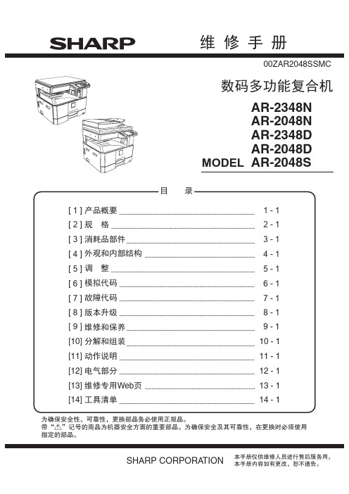
sharp2048维修手册
23cpm 23ppm 15/16ppm 23ppm 23ppm 18/16ppm 13ppm 13ppm 12/11/12ppm
(2) 旁路托盘
纸张尺寸 (短边给纸 ) A4/8.5"× 11" A4R/8.5"× 11"R A5/5.5"× 8.5" A5R/5.5"× 8.5"R B5/16K B5R/16KR 8.5" × 13" B4/8.5"× 14" A3/11" × 17"/8K
2) 振动很大的场所 振动很大的场所容易引起机器损坏。
3) 通风条件较差的场所 静电类型的复印机会在机器内部产生臭氧。机器的臭氧产生 量设计在一定水准以下, 避免引起人身伤害。但是, 连续长时 间使用机器也会产生臭氧的味道 , 因此应将机器安装在通风 条件好的地方, 并经常进行通风。
4) 阳光直射的地方 在阳光直射的地方机器的塑料部件和墨水容易引起变形 , 彼 岸色, 或变质, 从而导致机器损坏或脏复印。
400× 600dpi
RSPF
400× 600dpi
涉及图像传送特征
白 LED
256 级
黑白 : 1bit 灰阶 : 8bit 全彩 : RGB各颜色 8bit
扩充内存
MX-PK10
PS3 扩充组件
MX-USX5
SHARPDESK 5许可组件
STD: 标配 ○: 可以选购安装 -: 不能选购安装
AR-2048S ○
STD ○ ○ - - ○ ○
AR-2048D/2348D ○ ○ ○ ○ - ○ ○ ○
AR-2048N/2348N STD - ○ - ○ ○ ○ ○
Sangoh_DC2060_3060_3065_安装指导手册
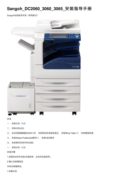
Sangoh_DC2060_3060_3065_安装指导⼿册Sangoh安装指导⼿册(常⽤部分)⽬录⼀.安装主机(1/2)⼆.安装主机(2/2)三.⾃动双⾯输稿器(DADF) 四.安装附加标准接收盘五.安装Wing Table 六.安装侧接收盘七.安装Adobe PostScript3配件⼋.安装HDD配件九.安装增设系统内存(2GB)⼀.安装主机(1/2)安装步骤1.拆除DADF的包装/包装胶带、主机的包装胶带。
2.确认包装随附品本机包装随附品1.机器主机2.INST USERS MANUAL PACKAGING Tray1中-包装随附品编号名称数量1 CD-ROM套件 12 使⽤说明书(仅限FX/FXCL) 13 设定说明书(仅限FX/FXCL) 14 快速参考说明书 15 安全⼿册(⽀持泰国PL法的永久版警⽰声明)16 纸张尺⼨标签 17 单触键标签 13.4.安装结束后,请从纸盘1取出说明书套件并交给客户,不要保留在纸盘中。
5.纸盘1中-包装随附品编号名称数量1 电源电缆(仅限FX/FXK/FXTW/FXCL) 12 Stopper(电源电缆专⽤) 13 Thumb Screw(电源电缆专⽤) 14 驱动程序CD配套(仅限ENG/FXK/FXCL) 15 Data Cable(FX:仅限配置传真功能的机型)16.纸盘2中-包装随附品编号名称数量1 SW KEY SHEET (APO/GCO) 12 NVM LIST 13 复印样本 14 记录表(仅限FX/FXCL) 15 安装步骤⼿册(仅限FX) 16 安装调查表(仅限FX) 17 保证书(仅限FXCL) 18 客户意见信(仅限FXCL) 19 操作培训说明确认⼿册(仅限FXCL)110 数据包列表(仅限FXCL) 17.Top Cover上-另⾏包装的随附品编号名称数量1 Drum Unit 12 Toner Cartridge18.Exit2 Tray Kit(仅限配置APO/GCO打印功能机型)编号名称数量1 Exit2 Tray 12 Paper Weight19.DONGLE USB Kit-另⾏包装的随附品(仅限FX)编号名称数量1 DONGLE USB 12 INST DONGLE 13 NAME LABEL 14 打印机驱动程序CD ROM(仅限配置打印功能机型)13.打开DADF Top Cover,拆下Retard Roll及Feed Roll的保护膜。
- 1、下载文档前请自行甄别文档内容的完整性,平台不提供额外的编辑、内容补充、找答案等附加服务。
- 2、"仅部分预览"的文档,不可在线预览部分如存在完整性等问题,可反馈申请退款(可完整预览的文档不适用该条件!)。
- 3、如文档侵犯您的权益,请联系客服反馈,我们会尽快为您处理(人工客服工作时间:9:00-18:30)。
Indicates an item of reference assisting the understanding of the topic in question.
REF.
Provides a description of a service mode.
Provides a description of the nature of an error indication.
direction of the electric signal. The expression "turn on the power" means flipping on the power switch, closing the front door, and closing the delivery unit door, which results in supplying the machine with power. 2. In the digital circuits, '1'is used to indicate that the voltage level of a given signal is "High", while '0' is used to indicate "Low".(The voltage value, however, differs from circuit to circuit.) In addition, the asterisk (*) as in "DRMD*" indicates that the DRMD signal goes on when '0'. In practically all cases, the internal mechanisms of a microprocessor cannot be checked in the field. Therefore, the operations of the microprocessors
Contents
Contents
Chapter 1 Specifications
1.1 Product Specifications ................................................................................................................................1- 1 1.1.1 Specifications .......................................................................................................................................................... 1- 1
Indicates an item requiring care to avoid electric shocks.
Indicates an item requiring care to avoid combustion (fire).
Indicates an item prohibiting disassembly to avoid electric shocks or problems.
Indicates an item requilug from the electric outlet.
Indicates an item intended to provide notes assisting the understanding of the topic in question.
This documentation uses the following symbols to indicate special information:
Symbol Description
Indicates an item of a non-specific nature, possibly classified as Note, Caution, or Warning.
used in the machines are not discussed: they are explained in terms of from sensors to the input of the DC controller PCB and from the output of the
DC controller PCB to the loads.
The descriptions in this Service Manual are subject to change without notice for product improvement or other purposes, and major changes will be communicated in the form of Service Information bulletins. All service persons are expected to have a good understanding of the contents of this Service Manual and all relevant Service Information bulletins and be able to identify and isolate faults in the machine."
Service Manual
Feeder DADF-P2
Jul 4 2007
Application
This manual has been issued by Canon Inc. for qualified persons to learn technical theory, installation, maintenance, and repair of products. This manual covers all localities where the products are sold. For this reason, there may be information in this manual that does not apply to your locality.
COPYRIGHT © 2001 CANON INC. Printed in Japan
Caution
Use of this manual should be strictly supervised to avoid disclosure of confidential information.
Symbols Used
Introduction
Introduction
The following rules apply throughout this Service Manual:
1. Each chapter contains sections explaining the purpose of specific functions and the relationship between electrical and mechanical systems with refer-
Chapter 2 Installation
2.1 Unpacking and Checking the Components ................................................................................................2- 1 2.1.1 Unpacking and Checking the Checking the Contents ............................................................................................. 2- 1
Trademarks
The product names and company names used in this manual are the registered trademarks of the individual companies.
Copyright
This manual is copyrighted with all rights reserved. Under the copyright laws, this manual may not be copied, reproduced or translated into another language, in whole or in part, without the written consent of Canon Inc.
ence to the timing of operation.
In the diagrams,
represents the path of mechanical drive; where a signal name accompanies the symbol , the arrow
indicates the
1.2 Names of Parts ...........................................................................................................................................1- 3 1.2.1 External View........................................................................................................................................................... 1- 3 1.2.2 Cross-section........................................................................................................................................................... 1- 3