A Linear Evolution for Non-Linear Dynamics and Correlations in Realistic Nuclei
NONLINEARELEMENTS:非线性元件
21.NONLINEAR ELEMENTS Earthquake Resistant Structures Should Have a Limited Number of Nonlinear Elements that can be Easily Inspectedand Replaced after a Major Earthquake.21.1 INTRODUCTION{ XE "Energy:Energy Dissipation Elements" }{ XE "Nonlinear Elements" }Many different types of practical nonlinear elements can be used in conjunction with the application of the Fast Nonlinear Analysis method. The FNA method is very effective for the design or retrofit of structures to resist earthquake motions because it is designed to be computationally efficient for structures with a limited number of predefined nonlinear or energy dissipating elements. This is consistent with the modern philosophy of earthquake engineering that energy dissipating elements should be able to be inspected and replaced after a major earthquake.Base isolators are one of the most common types of predefined nonlinear elements used in earthquake resistant designs. In addition, isolators, mechanical dampers, friction devices and plastic hinges are other types of common nonlinear elements. Also, gap elements are required to model contact between structural components and uplifting of structures. A special type of gap element with the ability to crush and dissipate energy is useful to model concrete and soil types of materials. Cables that can take tension only and dissipate energy in yielding are necessary to capture the behavior of many bridge type structures. In this chapter the behavior of several of those elements will be presented and detailed solution algorithms will be summarized.。
非线性动态方法评估重合钢筋建筑的地震抗性说明书
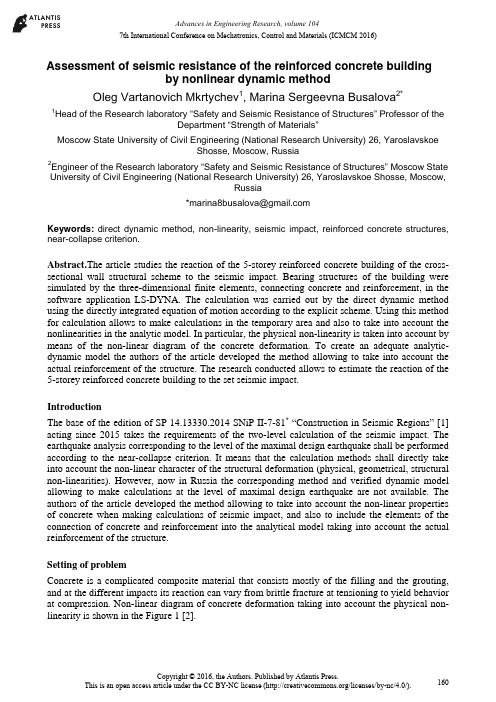
7th International Conference on Mechatronics, Control and Materials (ICMCM 2016)Assessment of seismic resistance of the reinforced concrete buildingby nonlinear dynamic methodOleg Vartanovich Mkrtychev1, Marina Sergeevna Busalova2*1Head of the Research laboratory “Safety and Seismic Resistance of Structures” Professor of theDepartment “Strength of Materials”Moscow State University of Civil Engineering (National Research University) 26, YaroslavskoeShosse, Moscow, Russia2Engineer of the Research laboratory “Safety and Seismic Resistance of Structures” Moscow State University of Civil Engineering (National Research University) 26, Yaroslavskoe Shosse, Moscow,Russia**************************Keywords:direct dynamic method, non-linearity, seismic impact, reinforced concrete structures, near-collapse criterion.Abstract.The article studies the reaction of the 5-storey reinforced concrete building of the cross-sectional wall structural scheme to the seismic impact. Bearing structures of the building were simulated by the three-dimensional finite elements, connecting concrete and reinforcement, in the software application LS-DYNA. The calculation was carried out by the direct dynamic method using the directly integrated equation of motion according to the explicit scheme. Using this method for calculation allows to make calculations in the temporary area and also to take into account the nonlinearities in the analytic model. In particular, the physical non-linearity is taken into account by means of the non-linear diagram of the concrete deformation. To create an adequate analytic-dynamic model the authors of the article developed the method allowing to take into account the actual reinforcement of the structure. The research conducted allows to estimate the reaction of the 5-storey reinforced concrete building to the set seismic impact.IntroductionThe base of the edition of SP 14.13330.2014 SNiP II-7-81* “Construction in Seismic Regions” [1] acting since 2015 takes the requirements of the two-level calculation of the seismic impact. The earthquake analysis corresponding to the level of the maximal design earthquake shall be performed according to the near-collapse criterion. It means that the calculation methods shall directly take into account the non-linear character of the structural deformation (physical, geometrical, structural non-linearities). However, now in Russia the corresponding method and verified dynamic model allowing to make calculations at the level of maximal design earthquake are not available. The authors of the article developed the method allowing to take into account the non-linear properties of concrete when making calculations of seismic impact, and also to include the elements of the connection of concrete and reinforcement into the analytical model taking into account the actual reinforcement of the structure.Setting of problemConcrete is a complicated composite material that consists mostly of the filling and the grouting, and at the different impacts its reaction can vary from brittle fracture at tensioning to yield behavior at compression. Non-linear diagram of concrete deformation taking into account the physical non-linearity is shown in the Figure 1 [2].Figure 1. Non-linear diagram of concrete deformationTo solve the problem it is necessary to have a corresponding material model. The Figure 2 shows the most complete models describing adequately the work of concrete at deformation (CSCM – Continuous Surface Cap Model) [3].Figure 2. Mathematical model of concrete (CSCM – Continuous Surface Cap Model) Concrete yield surface is described by the invariants of the stress tensor that in turn are determined from the formula (1)-(3).13J P=(1)212ij ijJ S S′=(2)313ij jk kiJ S S S′=(3)where1J is the first invariant of the stress tensor, 2J′ is the second invariant of the stress tensor, 3J′is the third invariant of the stress tensor,ijS is stress tensor, P is pressure.To study the actual reaction of the structure to the seismic impact it will not be sufficient to take into account the nonlinear properties of the concrete only. To show the real picture of thedeformation it is necessary to include the actual reinforcement into the analytic dynamic model, that is, to simulate the reinforcement cage of the building under analysis in the structural design [4].The Figure 3 shows the structural design of the five-storey reinforced concrete building of the cross-sectional wall structural scheme. All bearing structures are simulated by the three dimensional elements for concrete and bar elements for reinforcement [5].Figure 3. Structural design The Figure 4 shows the reinforcement cages of the building.Figure 4. Reinforcement cageCalculation resultsCalculation was made by the software application LS-DYNA by the direct dynamic method [6]. Equations of motion (4) were integrated directly according to the explicit scheme (5):a ++=Mu Cu Ku f (4)where u is nodal displacement vector, =uv is nodal velocity vector, =u a is nodal acceleration vector, M is mass matrix, C is damping matrix, K is rigidity matrix, af is vector of applied loads. /22t t t t t t t t t t +∆+∆+∆∆+∆=+u u v (5)This method allows to take into account the geometrical, physical and structural nonlinearities andalso to make calculations in the temporary area (dynamics in time).Three-component diagram was used as a design seismic impact corresponding to the intensity 9 earthquake (Figure 5). a)b)c)Figure 5. Three-component accelerograma)component X, b) component Y, c) component ZIsofields of the plastic deformations after the earthquake (t = 30 s) are shown in the Figure 6. Figure 6. Isofields of the plastic deformations after the earthquake at the moment of time t = 30 s The character of the plastic deformations corresponds completely to the character of cracks distribution. The Figure 6 shows that the bearing structures of the building of this structural scheme were damaged seriously but the building did not collapse, that means the conditions of the special limit state (near-collapse criterion) are satisfied. As a result of the conducted research, the seismic resistance of the building according to the near-collapse criterion was determined as intensity 9.ConclusionsThe analysis of the data obtained as a result of the research allows to conclude that for the adequate estimation of the reaction of the structure to the seismic impact it is necessary to make calculations in the nonlinear dynamic arrangement taking into account the nonlinear diagrams of concrete deformation and also to add the actual reinforcement into the structural design. The use of the offered method of the buildings earthquake calculations at the design stage will allow to estimate adequately the level of seismic resistance of the building structures.AcknowledgementsThis study was performed with the support of RF Ministry of Education and Science, grant No.7.2122.2014/K.References[1].SP 14.13330.2014 SNIP II-7-81. Stroitel'stvo v seysmicheskikh rayonakh[SP 14.13330.2014SNIP II-7-81. Construction in Seismic Areas]. (2014). Moscow: Analitik.[2].SP 63.13330.2012 SNIP 52-01-2003. Betonnye i zhelezobetonnye konstruktsii. Osnovnyepolozheniya[SP 63.13330.2012 SNIP 52-01-2003. Concrete and Reinforced Concrete Structures. Summary]. (2012). Moscow: Analitik.[3].Murray, Y.D. (2007). Users Manual for LS-DYNA Concrete Material Model 159. Report No.FHWA-HRT-05-062. U.S. Department of Transportation: Federal Highway Administration. [4].Murray, Y.D. (2007). Evaluation of LS-DYNA Concrete Material Model 159. Publication No.FHWA-HRT-05-063. U.S. Department of Transportation: Federal Highway Administration. [5].LS-DYNA. (n.d.). Keyword User’s Manual(Vol. 1, 2). Livermore Software TechnologyCorporation (LSTC).[6].Andreev, V.I., Mkrtychev, O.V., & Dzinchvelashvili, G.A. (2014). Calculation of Long SpanStructures to Seismic and Accidental Impacts in Nonlinear Dynamic Formulation. Applied Mechanics and Materials, 670-671, 764-768。
ANSYS LSDYNA在地震工程中的应用
第25卷第4期2005年8月地震工程与工程振动EARTHQuAKEENGINEERINGANDENGINEERINGVIBRATIONV01.25.No.4Aug.2005文章编号:1000-1301(2005)04.0170一04ANSYS/LS—DYNA在地震工程中的应用张冬茵1,金星1,丁海平1’2,孔戈1(1.中国地震局工程力学研究所,黑龙江哈尔滨150080;2.苏州科技大学土木系,江苏苏州215011)摘要:近年在国内很流行的大型通用程序ANsYs不但具有强大的前后处理功能、丰富的单元类型和材料库,而且该软件中有一个Ls—DYNA模块采用了粘性边界(viscousboundary)来模拟无限域的影响,从而可以方便地、较准确地进行地基动力作用分析。
国外利用ANsYS/Ls—DYNA进行地基动力作用分析非常普遍,而国内还未见到将ANSYs/Ls—DYNA用于地震工程。
本文将介绍如何利用ANsYS/Ls—DYNA进行地基动力作用分析,同时,由于软件中用于模拟无限域的粘性边界精度较低,本文提出采用精度较高的粘一弹性边界替换粘性边界,从而改善了计算结果。
关键词:有限元;Ls—DYNA软件;地震工程;数值模拟中图分类号:P315.98文献标识码:AApplicationofANSYS/LS-DYNAinearthquakeengineeringZhangDongyinl,JinXin91,DingHaipin91'2,KongGel(1.InstituteofEn舀neeringMechanics,ChinaEarthquakeAdministmtion,Harbin150080,China2.universityofscienceandTechnologyofsuzhou,suzh叫205011,china)Abstract:ANSYS,apopular1arge-scale6niteelementanalysissoftware,notonlyhasthepowe血lfunctionsofpre—processandpostprocess,abundantelementtypesandmateriallibrades,butalsohasmoduleofLS—DYNA,inwhichviscousboundaIyisadoptedtosimulatetheeⅡ’ectsofinfinitefield.Asaresult,itcansolVetheproblemsoffoundationdynamicanalysismoreefkctivelyandconveniently.LS—DYNAprogramhasbeenwidelyusedabroadtoanalyzefoundationdynamic,whileithasseldombeenusedinChina,especiaⅡyinthefieldofearthquakeengineer—ing.Inthispaper,theusageofLS—DYNAtoanalyzefbundationdynamicwiⅡbeintroduced6rst.Furthe瑚ore,be—causetheprecisionofviscousboundaryisnothi曲enough,viscous—sp“ngboundaryisintmducedtosubstituteforviscousboundary.Asdemonstratedbynumericalcalculationresults,thisapproachcanimproVethecalculatingpre—cisionobviously.Keywords:6niteelement;LS—DYNAsoftware;earthquakeengineering;numericalsimulation引言土一结构动力相互作用是地震工程领域中一个得到广泛关注的研究课题,它的研究对象涉及高层建筑、大型桥涵、地下工程、核电站、高水坝等与地基相连,并在动力荷载作用下与地基有相互作用影响的各种结构体系。
LS-DYNA积累手册

ANSYS/LSDYNA 平时积累手册显式与隐式方法对比:隐式时间积分——不考虑惯性效应([C]and[M])。
——在t+△t时计算位移和平均加速度:{u}={F}/[K]。
——线性问题时,无条件稳定,可以用大的时间步。
——非线性问题时,通过一系列线性逼近(Newton-Raphson)来求解;要求转置非线性刚度矩阵[k];收敛时候需要小的时间步;对于高度非线性问题无法保证收敛。
显式时间积分——用中心差法在时间t求加速度:{a}=([F(ext)]-[F(int)])/[M]。
——速度与位移由:{v}={v0}+{a}t,{u}={u0}+{v}t——新的几何构型由初始构型加上{X}={X0}+{U}——非线性问题时,块质量矩阵需要简单的转置;方程非耦合,可以直接求解;无须转置刚度矩阵,所有的非线性问题(包括接触)都包含在内力矢量中;内力计算是主要的计算部分;无效收敛检查;保存稳定状态需要小的时间步。
关于文件组织:jobname.k——lsdyna输入流文件,包括所有的几何,载荷和材料数据jobname.rst——后处理文件主要用于图形后处理(post1),它包含在相对少的时间步处的结果。
jobname.his——在post26中使用显示时间历程结果,它包含模型中部分与单元集合的结果数据。
时间历程ASCII文件——包含显式分析额外信息,在求解之前需要用户指定要输出的文件,它包括:GLSTAT全局信息,MATSUM材料能量,SPCFORC节点约束反作用力,RCFORC 接触面反作用力,RBDOUT刚体数据,NODOUT节点数据,ELOUT单元数据……在显式动力分析中还可以生成下列文件:D3PLOT——类似ansys中jobname.rstD3THDT——时间历程文件,类似ansys中jobname.his关于单元:ANSYS/LSDYNA有7中单元(所有单元均为三维单元):LINK160:显式杆单元;BEAM161:显式梁单元;SHELL163:显式薄壳单元;SOLID164:显式块单元;COMBI165:显式弹簧与阻尼单元;MASS166:显式结构质量;LINK167:显式缆单元显式单元与ansys隐式单元不同:——每种单元可以用于几乎所有的材料模型。
非线性有限元的有关著作和简要历史

非线性有限元的有关著作和简要历史作者:庄茁译已经发表的一些成功的实验和专题文章,完全或者部分地对非线性有限元分析做出了贡献。
仅论述非线性有限元的作者包括Oden(1972),Crisfield(1991),Kleiber(1998)和Zhong(1993)。
特别值得注意的时Oden的书,因为它时固体和结构非线性有限元的先驱作者。
最近的作者又Simo和Hughes(1998)、Bonet和Wood(1997)。
某些作者还部分的非线性分析做出了贡献,他们是Belytschko和Hunhes(1983),Zienkiewicz和Taylor(1991),Bathe(1996),以及Cook,Malkushe和Plesha(1989)。
对于非线性有限元分析,他们的书提供了有益的入门指南。
作为姐妹篇,线性有限元分析的论述也是有用的,内容最全面的是Hughes(1987)、Zienkiewicz和Taylor(1991)的著作。
下面我们回顾非线性有限元方法的简单历史。
本书与其它书的写作思路有些区别,我们不仅关注发表的文章,而且更关注软件的发展。
在这个信息—计算机时代,像许多其它方面的进步一样,在非线性有限元分析中,软件常常比文献更好的代表了最新的进展。
非线性有限元方法有多种溯源。
通过波音研究的工作和Turner,Clough,Martin和Yopp (1956)的著名文章,使线性有限元分析得以闻名,不久之后,在许多大学和研究所里,工程师们开始将方法扩展至非线性、小位移的静态问题。
但是,它难以燃起早期有限元社会的激情和改变传统研究者们对于这些方法的鄙视。
例如,因为考虑到没有科学的是实质,《Journal of Applied Mechanics》许多年都拒绝刊登关于有限元方法的文章。
然而。
对于许多必须涉及工程问题的工程师们,他们非常清楚有限元方法的前途,因为它提供了一种处理复杂形状真实问题的可能性。
在20世纪60年代,由于Ed Wilson发布了他的第一个程序,这种激情终于被点燃了。
LS-DYNA的中文教程

第二部分 ANSYS/LS-DYNA 程序的使用方法一、概述ANSYS/LS-DYNA 程序系统是将非线性动力分析程序LS-DYNA 显式积分部分与ANSYS 程序的前处理PREP7和后处理POST1、POST26连接成一体。
这样既能充分运用LS-DYNA 程序强大的非线性动力分析功能,又能很好地利用ANSYS 程序完善的前后处理功能来建立有限元模型与观察计算结果,它们之间的关系如下。
Jobname.DBJobname.RST d3plotJobname.HIS d3thdtANSYS/LS-DYNA 程序系统的求解步骤为:(一)前处理Preprocessor 建模(用PREP7前处理解算器)1.设置Preference(Main Menu:Preference)选项置Structural LS-DYNA explicit 。
这样,以后显示的菜单完全被过滤成ANSYS/LS-DYNA 的输入选项。
再定义一种显式单元类型,即可激活LS-DYNA 求解。
GUI: Main Menu>Preferencesa.选择Structural.b.选择LS-DYNA Explicit.c.OK.2.定义单元类型Element Type 和Option (算法)和实常数Real Constant 。
3.定义材料性质Material Properties 。
4.建立结构实体模型Modeling 。
5.进行有限元网格剖分Meshing 。
6.定义接触界面Contact 。
(二)加载和求解Solution1.约束、加载和给定初始速度。
2.设置求解过程的控制参数。
ANSYS 前处理PREP7 ANSYS/LS-DYNA ANSYS 后处理POST1,POST26 后处理LS-TAURUS Jobname.k3.选择输出文件和输出时间间隔。
4.求解Solve(调用LS-DYNA)。
(三)后处理POST1(观察整体变形和应力应变状态)和POST26(绘制时间历程曲线),也可连接LSTC公司的后处理程序LS-TAURUS。
非线性有限元解法

(9)
(10 )
•在增量方法中通常引入载荷因子λ,用 R R表示载荷, 于是非线性有限
元方程可写成: ( u, ) P( u ) R 0
(1)
用载荷因子λ系列: 0 0 1 2 M 1
(2)
相应于不同的载荷。
若相应于载荷因子 n 的解已经求得,记为 u un ,则 ( un ,n ) P( un ) n R 0
KT n
KT ( un
)
un
(8)
un1 un un
其收敛判据与直接迭代法的收敛判据雷同。
非线性有限元方程组的解法(增量法)
•求解非线性方程组的另一类方法是增量方法。使用增量方法的一个优点是 可以得到整个载荷变化过程的一些中间的数值结果。当问题的性质与加载的 历史有关时,例如弹塑性问题,则必须采用增量方法。
u1 ( K1 )1 R
据此容易写出直接迭代法的迭代公式:
Kn K( un )
un1 ( K n )|1 R
(2)
按照这种迭代公式可以得到一个解数列 { un } ,当这个数列收敛时停止计
算,其数列收敛值就是方程(1)的解。
非线性有限元方程组的解法(直接迭代法)
关于数列收敛的判据,可以采用各种各样的范数定义和收敛判据。若设第 n
( un ) K( un )un R 0
(7)
该值可作为对偏离平衡的一种度量(称为失衡力),收敛判据可相应地取为:
( un ) R
(8)
(失衡力收敛判据)
非线性有限元方程组的解法(牛顿法)
把非线性有限元方程记为: ( u ) P( u ) R 0 (1)
复变函数差分方程
Entire solutions of certain type of difference equations
Nana Liu1 , Weiran Lü1* , Tiantian Shen1 and Chungchun Yang2
Correspondence: luwr@ Department of Mathematics, China University of Petroleum, Qingdao, 266580, P.R. China Full list of author information is available at the end of the article
k
d := d P(z, f ) = max
≤l≤n
nlj .
j=
For the sake of simplicity, we let
f (z) = f (z + ) – f (z),
n
f (z) =
(
n–
f (z)) (n ≥ ).
Yang and Laine [] considered the following difference equation and proved it. Theorem A A non-linear difference equation f (z) + q(z)f (z + ) = c sin bz, where q(z) is a non-constant polynomial and b, c ∈ C are nonzero constants, does not admit entire solutions of finite order. If q(z) = q is a nonzero constant, then the above equation possesses three distinct entire solutions of finite order, provided that b = nπ and q = (–)n+ c / for a nonzero integer n. Now, we shall substitute f (z + ) by f (z) in Theorem A and prove the following results
- 1、下载文档前请自行甄别文档内容的完整性,平台不提供额外的编辑、内容补充、找答案等附加服务。
- 2、"仅部分预览"的文档,不可在线预览部分如存在完整性等问题,可反馈申请退款(可完整预览的文档不适用该条件!)。
- 3、如文档侵犯您的权益,请联系客服反馈,我们会尽快为您处理(人工客服工作时间:9:00-18:30)。
‡ ⋆
Email: leving@post.tau.ac.il, levin@mail.desy.de. Email: lublinm@mail.desy.de
1ቤተ መጻሕፍቲ ባይዱ
1
Introduction
High density QCD [1, 2, 3, 4, 5] which is a theory of Color Glass Condensate deals with parton systems with large gluon occupation numbers. It has entered a new phase of its development: a direct comparison with the experimental data. A considerable success [6, 7, 8, 9, 10, 11, 12, 13, 14, 15] has been reached in description of new precise data on deep inelastic scattering [16] as well as in understanding of general features of hadron production in ion-ion collision [17]. Most of the applications of hdQCD are based on or related to a nonlinear evolution equation derived for high density QCD [1, 2, 18, 19]. The equation sums ’fan’ diagrams, which is a subset of the semi-enhanced diagrams. In order to obtain a closed form equation it is usually assumed that color dipoles produced by the evolution interact independently [1, 19]. It was noticed in Ref. [11] that the nonlinear evolution equation based on the above assumption faces problems when applied to realistic nuclei. It was realized that in addition to multiple rescatterings on nucleons inside a nucleus we have to include in the analysis multiple rescatterings inside a single nucleon. This means a need to account for nucleus correlations. It is our motivation for this research to develop a systematic approach which would allow us to introduce correlations inside a target. We have found that a convenient language to address the problem of target correlations is using the QCD generating functional, for which a linear evolution equation can be written. The generating functional was introduced by Mueller in Ref. [20] and then used by Kovchegov in his derivation of the non-linear evolution equation for interaction amplitude [19]. In the present paper, we show that this functional (and the amplitude) obeys a linear evolution equation involving functional derivatives with respect to initial conditions. For the linear equation we propose a systematic method to include target correlations. In general, the linear equation for the amplitude with target correlations cannot be transformed to a non-linear one. For a specific choice of correlations we are able to reduce the linear equation to a non-linear form similar to the BalitskyKovchegov (BK) equation. In fact, our new equation is a model dependent generalization of the BK equation for targets with correlations. It is important to stress that we consider the very same functional as of Mueller. The evolution of the dipole wave function is still based on independent production of dipoles. Only correlations for the dipole-target interaction are introduced. Let us discuss now realistic nuclei and reasons why we believe target correlations are essential there. In principal, the BK equation is correct for hadron targets as well as for heavy nuclei. For the latter the large A limit is usually assumed which adds an additional justification to the equation validity. In this case a nucleus is viewed as a very dense system of nucleons. We are going to relax this assumption. In fact the realistic nuclei are not very dense but rather dilute [10, 13]. The diluteness parameter that governs the interaction with nuclei could be expressed in the form: 2 κA (b) = π RN SA (b) , (1.1)
The parameter κA ∝ A 3 and , in principle, is large for heavy nuclei. It turns out, however, that the gluons are distributed inside a nucleon within a rather small area with radius of the order 2
2 where πRN is the effective area in which gluons of a nucleon are distributed. SA (b) stands for a nucleus profile function, which can be taken as the Wood-Saxon form factor of the nucleus.
and M. Lublinsky
b) ⋆
HEP Department School of Physics and Astronomy Raymond and Beverly Sackler Faculty of Exact Science Tel Aviv University, Tel Aviv, 69978, Israel
b)
a)
DESY Theory Group, DESY D-22607 Hamburg, Germany
Abstract
A new approach to high energy evolution based on a linear equation for QCD generating functional is developed. This approach opens a possibility for systematic study of correlations inside targets, and, in particular, inside realistic nuclei. Our results are presented as three new equations. The first one is a linear equation for QCD generating functional (and for scattering amplitude) that sums the ’fan’ diagrams. For the amplitude this equation is equivalent to the non-linear Balitsky-Kovchegov equation. The second equation is a generalization of the Balitsky-Kovchegov non-linear equation to interactions with realistic nuclei. It includes a new correlation parameter which incorporates, in a model dependent way, correlations inside the nuclei. The third equation is a non - linear equation for QCD generating functional (and for scattering amplitude) that in addition to the ’fan’ diagrams sums the Glauber-Mueller multiple rescatterings.