AZ23C2V7-V中文资料
V23079中文资料
P2 RelayThe Best Rela ytion90012 pole telecom relay, polarized,Through Hole Type (THT) orSurface Mount Technology (SMT),Relay types: non-latching with 1 coil latching with 2 coils latching with 1 coilFeatures– Standard telecom relay (ringing and test access)– Slim line 15 x 7.5 mm, 0.590 x 0.295 inch – Switching current 5 A– 2 changeover contacts (2 form C / DPDT)– Bifurcated contacts – Immersion cleanable– High sensitivity results in low nominal power consumption 140 mW for non-latching and latching with 2 coils 70 mW for latching with 1 coil – For single coil version:- Surge voltage resistance between contact and coil for single coil version:- 2.5 kV (2 / 10 µsec) meets the Bellcore Requirement GR-1089 - 1.5 kV (10 / 160 µsec) meets FCC Part 68Typical applications– Communications equipmentlinecard application (ringing and test access) PABXVoice over IP – Office equipment– Measurement and control equipment – Automotive equipmentCAN bus, keyless entry, speaker switch – Medical equipment – Consumer electronics Set Top Boxes, HiFiOptions– 1500 Vrms between open contacts – Temperature range up to 105° CUL 508 File No. E111441UL 60950QC 160504-CH0003CECC 811-54-003Insulation category:Supplementary insulation according IEC / EN 60950Working voltage ³ 300 Vrms Mains supply voltage ³ 250 Vrms Repetitive peak voltage 2500 V Pollution degree: Internal: 1 External: 2Flammability classification: V-0Maximum operating temperature: 85 °CIEC/EN60950 IEC Ref. Cert. No. CH 2171DimensionsTHT THT SMT long terminals SMT long terminals SMT short terminals SMT short terminals V23079-x1xxx-B301 V23079-x2xxx-B301 V23079-x1xxx-B301 V23079-x2xxx-B301V23079-x1xxx-B301 V23079-x2xxx-B301 standard coil overmolded coil standard coil overmolded coil standard coil overmolded coilmm inch mm inch mm inch mm inch mm inch mm inchL 14.5 ± 0.1 0.570 ± 0.004 14.5 ± 0.1 0.570 ± 0.00414.5 ± 0.1 0.570 ± 0.00414.5 ± 0.10.570 ± 0.00414.5 ± 0.1 0.570 ± 0.00414.5 ± 0.10.570 ± 0.004 W 7.2 ± 0.1 0.283 ± 0.004 7.2 ± 0.1 0.283 ± 0.0047.2 -0.15 0.283 ± 0.0047.2 -0.15 0.283 ± 0.0047.2 -0.15 0.283 ± 0.0047.2 -0.15 0.283 ± 0.004 H9.8 ± 0.1 0.385 ± 0.004 9.5 ± 0.1 0.374 ± 0.00410.4 ± 0.15 0.409 ±0.006 9.9 ± 0.1 0.390 ± 0.00410.4 ± 0.150.409 ±0.006 9.9 ± 0.1 0.390 ± 0.004 T 3.25 - 0.25 0.128 -0.010 3.25 - 0.25 0.128 -0.010N/A N/A N/A N/A N/A N/A N/A N/AT1 N/A N/A N/A N/A 5.52 ±0.15 0.217 ±0.006 5.52 0.217 ±0.006 5.52 0.217 ±0.006 5.52 0.217 ±0.006 T2 N/A N/A N/A N/A 9.4 ±0.15 0.370 ±0.006 9.4 ±0.15 0.370 ±0.006 7.4 ±0.15 0.291 ±0.006 7.4 ±0.15 0.291 ±0.006 Tw0.5 ± 0.05 0.020 ±0.002 0.5 ± 0.05 0.020 ±0.0020.5 ± 0.05 0.020 ±0.002 0.5 ± 0.050.020 ±0.002 0.5 ± 0.05 0.020 ±0.002 0.5 ± 0.050.020 ±0.002 S 0.55 - 0.15 0.022 -0.0060.45 0.018 ±0.002N/A N/A N/A N/A N/A N/A N/A N/ATHT VersionNote: Hole for pin 6 and 7only for latching with 2 coilsBasic grid 2.54 mmLong terminalsSMT VersionShort terminalsNote: Solder pad for pin 6 and 7only for latching with 2 coilsNote: Solder pad for pin 6 and 7only for latching with 2 coilsLong terminals Short terminalsTerminal assignmentRelay - top viewLatching type, 2coilsreset condition Mounting hole layoutView onto the component side of the PCBSolder pad layoutView onto the component side of the PCBNon-latching type,not energized conditionLatching type, 1 coilreset conditionnon-latching 1 coilA1xxx/D1xxx/G1xxx A2xxx/D2xxx/G2xxx3 2.25 6.50 0.30 140 64.3 0084 3.00 8.70 0.40 140 114 016 4.5 3.375 9.80 0.45 140 145 011 5 3.75 10.90 0.50 140 178 0016 4.5 13.00 0.60 140 257 002 9 6.75 19.60 0.90 140 578 006 12 9.00 26.15 1.20 140 1029 003 24* 18.00 52.30 2.40 140 4114 005 3 2.25 6.50 2.25 140 64.3 208 4.5 3.375 9.80 3.375 140 145 211 5 3.75 10.90 3.75 140 178 201 6 4.5 13.00 4.50 140 257 202 9 6.75 19.60 6.75 140 578 206 12 9.00 26.15 9.00 140 1029 203 24 18.00 52.30 18.00 140 4114 205latching 2 coilslatching 1 coil3 2.25 9.20 2.25 70 128 108 4.5 3.375 13.85 3.375 70 289 111 5 3.75 15.33 3.75 70 357 101 6 4.5 18.50 4.50 70 514 102 9 6.75 27.75 6.75 70 1157 106 12 9.00 37.00 9.00 70 2057 103 24 18.00 74.00 18.00 70 8228 105* 24 V only in A1xxx/D1xxx/G1xxxFurther coil versions are available on request.Ambient temperature t amb [°C]B1xxx/E1xxx/H1xxxC1xxx/F1xxx/J1xxxU I = Minimum voltage at 23° C after pre-energizing with nominal voltage without contact current U II = Maximum continous voltage at 23°The operating voltage limits U I and U II depend on the temperature according to the formula:U I tamb = K I · U I 23° C and U II tamb = K Il · U Il 23° Ct amb = Ambient temperatureU I tamb = Minimum voltage at ambient temperature, t amb U II tamb = Maximum voltage at ambient temperature, t amb k I , k II = Factors (dependent on temperature), see diagramAll data refers to 23° C unless otherwise specified.Recommended soldering conditionsSoldering conditions according CECC 00802Vapor Phase Soldering: Temperature/Time Profile (Lead Temperature)Infrared Soldering: Temperature/Time Profile (Lead Temperature)Time (s)Time (s)T e m p e r a t u r e °CT e m p e r a t u r e °CTube for THT version - 50 relays per tube, 2000 relays per boxTape and reel for SMT version with long terminals - 400 relays per reel, 2000 relays per boxTape and reel for SMT version with short terminals - 500 relays per reel, 2500 relays per boxReel dimensionDimensions in mmPackingV23079-A1001-B301 0-1393788-3 V23079-A1002-B301 0-1393788-8 V23079-A1003-B301 1-1393788-1 V23079-A1005-B301 1-1393788-6 V23079-A1006-B301 2-1393788-0 V23079-A1008-B301 2-1393788-2 V23079-A1011-B301 2-1393788-4 V23079-A2001-B301 3-1393789-5 V23079-A2002-B301 3-1393789-6 V23079-A2003-B301 3-1393789-7 V23079-A2005-B301 0-1393790-2 V23079-A2006-B301 3-1393789-8 V23079-A2008-B301 6-1419120-6 V23079-A2011-B301 3-1393789-9 V23079-B1201-B3013-1393788-3 V23079-B1202-B3013-1393788-5 V23079-B1203-B3013-1393788-6 V23079-B1205-B3013-1393788-7 V23079-B1206-B3013-1393788-9 V23079-B1208-B3014-1393788-1 V23079-B1211-B3014-1393788-2 V23079-C1101-B301 4-1393788-5 V23079-C1102-B301 4-1393788-7 V23079-C1103-B301 4-1393788-8 V23079-C1105-B301 5-1393788-0 V23079-C1106-B301 5-1393788-1 V23079-C1108-B301 5-1393788-3 V23079-C1111-B301 5-1393788-4 V23079-D1001-B301 5-1393788-5 V23079-D1002-B301 5-1393788-6 V23079-D1003-B301 5-1393788-7 V23079-D1005-B301 5-1393788-8 V23079-D1006-B301 5-1393788-9 V23079-D1008-B301 6-1393788-1 V23079-D1011-B301 6-1393788-2 V23079-D2001-B301 4-1393789-3 V23079-D2002-B301 4-1393789-4 V23079-D2003-B301 4-1393789-5 V23079-D2006-B301 4-1393789-6 V23079-D2008-B301 4-1393789-7 V23079-D2011-B301 4-1393789-8V23079-E1201-B3016-1393788-8 V23079-E1202-B3010-1393789-5 V23079-E1203-B3016-1393788-9 V23079-E1205-B3017-1393788-0 V23079-E1206-B3010-1393789-9 V23079-E1208-B3017-1393788-1 V23079-E1211-B3017-1393788-2 V23079-F1101-B301 7-1393788-3 V23079-F1102-B301 1-1393789-0 V23079-F1103-B301 7-1393788-4 V23079-F1105-B301 1-1393789-1 V23079-F1106-B301 1-1393789-2 V23079-F1108-B301 7-1393788-5 V23079-F1111-B301 1-1393789-4 V23079-G1001-B301 7-1393788-6 V23079-G1002-B301 1-1393789-5 V23079-G1003-B301 7-1393788-7 V23079-G1005-B301 7-1393788-8 V23079-G1006-B301 1-1393789-6 V23079-G1008-B301 8-1393788-0 V23079-G1011-B301 1-1393789-7 V23079-G2001-B301 4-1393789-9 V23079-G2002-B301 5-1393789-0 V23079-G2003-B301 5-1393789-1 V23079-G2006-B301 5-1393789-3 V23079-G2008-B301 5-1393789-4 V23079-G2011-B301 5-1393789-5 V23079-H1201-B301 2-1393789-0 V23079-H1202-B301 2-1393789-1 V23079-H1203-B301 8-1393788-3 V23079-H1205-B301 2-1393789-2 V23079-H1206-B301 2-1393789-3 V23079-H1208-B301 2-1393789-4 V23079-H1211-B301 8-1393788-4 V23079-J1101-B301 2-1393789-5 V23079-J1102-B301 2-1393789-6 V23079-J1103-B301 2-1393789-7 V23079-J1105-B301 2-1393789-8 V23079-J1108-B301 2-1393789-9 V23079-J1111-B301 3-1393789-0Relay Code TycoPart Number Relay Code TycoPart NumberOrdering Information Middle block of relay codeV23079-yyxxx-B301yy : See table belowxxx : See coil table on page 4yy DescriptionA1 THT, non latching, standard coilA2 THT, non latching, overmolded coil B1 THT, latching, 2 standard coilsC1 THT, latching, 1 standard coil D1 SMT, long pins, non latching, standard coil D2 SMT, long pins, non latching, overmolded coilE1 SMT, long pins, latching, 2 standard coils F1 SMT, long pins, latching, 1 standard coilG1 SMT, short pins, non latching, standard coil G2 SMT, short pins, non latching, overmolded coilH1 SMT, short pins, latching, 2 standard coils J1 SMT, short pins, latching, 1 standard coilDimensionsSMT short terminals V23079-G2xxx-X0xx overmolded coilmm inchL 14.5 ± 0.1 0.570 ± 0.004 W 7.2 -0.15 0.283 ± 0.004 H9.9 ± 0.1 0.390 ± 0.004 T N/A N/AT1 5.52 0.217 ±0.006 T2 7.4 ±0.15 0.291 ±0.006 Tw0.5 ± 0.05 0.020 ±0.002 S N/A N/ASMT Versionnon-latching1 coilV23079-5 3.75 10.90 0.50 140178 G2001-X0716 4.50 13.00 0.60 140257 G2002-X0729 6.75 19.60 0.90 140578 G2006-X07312 9.00 26.15 1.20 140 1029 G2003-X074 This supplementary data sheet refers to the basic data sheet of the P2 relay series (V23079) with following additions:-Dielectric strength 1500 Vrmsbetween open contacts - as well as between coil and contacts and between adjacent contact sets-Only non-latching types available-SMT version with short terminals as preferred type-mechanical and electrical endurance typ. 106 operationsOption: high dielectric between open contacts (overmolded coil)V23079-G2001-X071 0-1422006-1V23079-G2002-X072 0-1422006-2V23079-G2006-X073 0-1422006-3V23079-G2003-X074 0-1422006-4Relay Code TycoPart NumberOrdering InformationNote: Solder pad for pin 6 and 7only for latching with 2 coilsSolder pad layoutIM Relays4th generation slim line – low profile polarized 2 c/o telecom relay with bifurcated contacts, available as non latching or latching relay with1 coil. Nominal voltage range from 1.5... 24 V, coil power consumption of 140... 200 mW, latching relays with 1 coil 100 mW. The IM relayis available as through hole and surface mount type (J-Legs and Gull Wings) and capable to switch loads up to 60 W/62,5 VA. Dielectric strength fulfills the Bellcore requirements according GR 1089 (2,5 kV – 2 / 10 µs) and FCC part 68 (1,5 kV – 10 / 160 µs). The IM relay is CECC/IECQ approved and certified in accordance with IEC/EN 60950 and UL1950. Dimensions approx. 10 x 6 mm board space and5.65 mm height.P2 Relays3rd generation polarized 2 c/o telecom relay with bifurcated contacts, available as non latching or latching relay with 1 or 2 coils. Nominal voltage range from 3 ... 24 V, coil power consumption 140 mW, latching relays with 1 coil 70 mW. The P2 Relay is available as through hole or surface mount type and capable to switch currents up to 5A. Dielectric strength fulfills the Bellcore requirements according GR 1089 (2,5 kV – 2 / 10 µs) and FCC part 68 (1,5 kV – 10 / 160 µs). Dimensions approx. 15 x 7,5 mm board space and 10 mm height.FX Relays3rd generation polarized 2 c/o telecom relay with bifurcated contacts, available as non latching or latching relay with 1 coil. Nominal voltage range from 3 ... 48 V, coil power consumption of 80 ... 260 mW for the high sensitive version, 140... 300 mW for the standard version, latching relays with 1 coil 100 mW. The FX2 relay is available as through hole type and capable to switch loads up to 60 W/62,5 VA. Dielectric strength fulfills the Bellcore requirements according GR 1089 (2,5 kV – 2 / 10 µs) and FCC part 68 (1,5 kV – 10 / 160 µs). The FX2 is CECC/ IECQ approved and certified in accordance with IEC/EN 60950 and UL1950. Dimensions approx. 15 x 7,5 mm board space and 10,7 mm height.FT2 / FU2 Relays3rd generation non polarized, non latching 2 c/o telecom relay with bifurcated contacts. Nominal voltage range from 3 ... 48 V, coil power consumption 200 ... 300 mW. Most sensitive 48 V relay. Available as through hole and surface mount type. Dielectric strength fulfills the Bellcore requirements according GR 1089 (2,5 kV – 2 / 10 µs) and FCC part 68 (1,5 kV – 10 / 160 µs). The FT2/FU2 is CECC/IECQ approved and certified in accordance with IEC/EN 60950 and UL1950. Dimensions approx. 15 x 7,5 mm board space and 10 mm height.FP1 Relays3rd generation polarized 2 c/o telecom relay with bifurcated contacts, available as non latching or latching relay with 1 or 2 coils. Nominal voltage range from 3 ... 48 V, coil power consumption of 80 ... 260 mW for the high sensitive version, 140... 300 mW for the standard version, latching relays with 1 coil 100 mW.. The FP1 Relay is available as through hole type and capable to switch loads up to30 W/62,5 VA. Dielectric strength fulfills FCC part 68 (1,5 kV – 10 / 160 µs). The FP2 is CECC/IECQ approved. Dimensions approx.14 x 9 mm board space and 5 mm height.MT2 / MT42nd generation non polarized, non latching 2 c/o and 4 c/o telecom and signal relay with bifurcated contacts. Nominal voltage range from 4.5 ...48 V, coil power consumption 150/200/300/400 and550 mW, and 300 mW (MT4). Dielectric strength fulfills the requirements according FCC part 68 (1,5 kV – 10 / 160 µs) for both and the Bellcore requirements according GR 1089 (2,5 kV – 2 / 10 µs) the MT4 only.Dimensions MT2 approx. 20 x 10 mm board space and 11 mm height, MT4 approx. 20 x15 mm board space and 11 mm height.D2n Relays2nd generation non polarized 2 c/o relay for telecom and various other applications. Nominal voltage range from 3 ... 48 V, coil power consumption from 150 .... 500 mW. The D2n relay is capable to switch currents up to 3 A. Dielectric strength fulfills the requirements according FCC part 68 (1,5 kV – 10 / 160 µs). Dimensions approx.20 x10 mm board space and 11,5 mm height.P1 RelaysExtremely sensitive, polarized 1 c/o relay with bifurcated contacts for a wide range of applications, available as non latching or latching relay with 1 or 2 coils. Nominal voltage range from 3 ... 24 V, coil power consumption 65 mW, latching relays with 1 coil 30 mW. The P1 relay is available as through hole or surface mount type and capable to switch currents up to 1 A. Dielectric strength fulfills the requirements according FCC part 68 (1,5 kV – 10 / 160 µs). Dimensions approx.13 x 7,6 mm board space and 7 mm height for THT or 8 mm height for SMT version.W11 RelaysLow cost, non polarized 1 c/o relay for various applications. Nominal voltage range from 3 ... 24 V, coil power consumption 450 mW, sensitive versions 200 mW. The W11 relay is capable to switch currents up to 3 A. Dielectric strength 1000 Vrms. Dimensions approx. 15,6 x 10,6 mm board space and 11,5 mm height.Reed RelaysHigh sensitive, non polarized relay for telecom and various other applications, available with 1 n/o, 2 n/o or 1c/o contacts. Nominal voltage range from 5 ... 24 V, coil power consumption 50...280 mW for 1 n/o and 125 ... 280 mW for 2 n/o or 1 c/o versions. Reedrelays are available in DIP or SIL housing and capable to switch currents up to 0,5 A. Integrated diode and/or electrostatic shield optional. Dielectric strength 1500 Vdc. Dimensions approx. 19,3 x 7 mm board space and 5 ... 7,5 mm height for DIP or 19,8 x 5 mm board space and 7,8 mm height for SIL version.Cradle RelaysExtremely reliable and mature relay family of 1st generation for various signal switching applications. Available as non polarized, polarized/ latching and relay with AC coil. The benefit is the possibility of combining various contact sets from 1 up to 6 poles, single and bifurcated contacts, different contact materials with a coil voltage range from 1,5 Vdc to 220 Vac. Cradle relays are available as dust protected and hermetically sealed versions, with plug in or solder terminals and are capable to switch currents up to 5 A. Forcibly guided (linked) contact sets optional. Dielectric strength 500 Vrms. Dimensions from approx. 19 x 24 to 19x35 mm board space and30 mm height.Other RelaysWe offer a variety of different relay families for maintenance and replacement purposes. These relays are up to 60 years old now, such as Card Relay SN (V23030 / V23031 series), Small General Purpose Relay (V23006 series), Small Polarized Relay (V23063 (V23067)and V23163 ... V23167 series). Accessories like sockets, hold down springs, etc. optional.HF3 RelayHigh performance low cost RF relay with excellent RF characteristics. Available with an impedance of 50 and 75 Ohm. Suitable for frequen-cies up to 3 GHz. Actually smallest RF relay available combining small size, excellent RF performance and SMD solderability. Available as non latching or latching relay with 1 or 2 coils and a nominal coil voltage range from 3 ... 24 V, coil power consumption 140 mW, latching relays with 1 coil 70 mW. Dimensions 14.6 x 7.3 x 10 mm.Tyco Electronics AXICOM Ltd.Seestrasse 295 - P.O. Box 220CH-8804 Au-Wädenswil / Switzerland Phone +41 1 782 9111Fax +41 1 782 9080E-mail: axicom@ Tyco Electronics Corporation POB 3608,Harrisburg, PA 17105, USA Phone +001 800-522-6752Tyco Electronics EC Trutnov s.r.o.Komenského 821CZ-541 01 Trutnov / Czech Republic E-mail: axicom@ Tyco Electronics AMP GmbHPaulsternstrasse 26D-13629 Berlin / GermanyPhone +49 30 386 38260Fax +49 30 386 38569E-mail: axicom@ F e b r u a r y 2003 R e v . 2.0811元器件交易网。
遥控器对照表大全
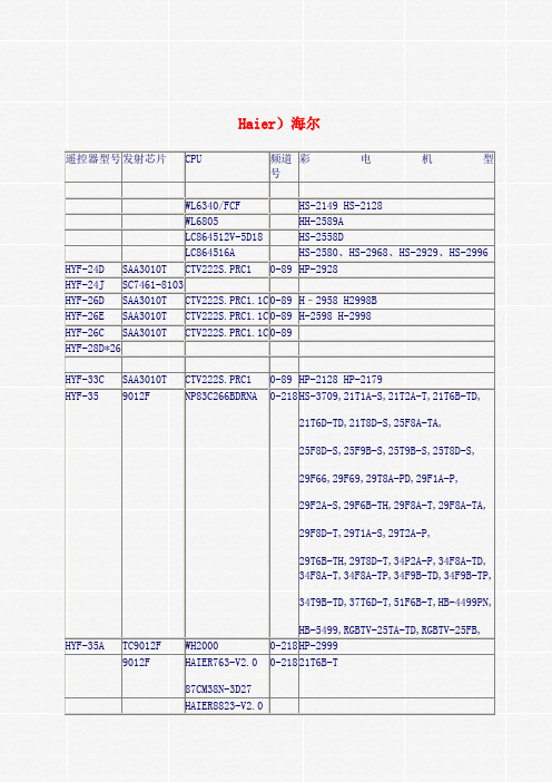
Haier)海尔遥控器型号发射芯片CPU 频道彩电机型号WL6340/FCF HS-2149 HS-2128WL6805 HH-2589ALC864512V-5D18 HS-2558DLC864516A HS-2580、HS-2968、HS-2929、HS-2996 HYF-24D SAA3010T CTV222S.PRC1 0-89 HP-2928HYF-24J SC7461-8103HYF-26D SAA3010T CTV222S.PRC1.1C 0-89 H–2958 H2998BHYF-26E SAA3010T CTV222S.PRC1.1C 0-89 H-2598 H-2998HYF-26C SAA3010T CTV222S.PRC1.1C 0-89HYF-28D*26HYF-33C SAA3010T CTV222S.PRC1 0-89 HP-2128 HP-2179HYF-35 9012F NP83C266BDRNA 0-218 HS-3709,21T1A-S,21T2A-T,21T6B-TD,21T6D-TD,21T8D-S,25F8A-TA,25F8D-S,25F9B-S,25T9B-S,25T8D-S,29F66,29F69,29T8A-PD,29F1A-P,29F2A-S,29F6B-TH,29F8A-T,29F8A-TA,29F8D-T,29T1A-S,29T2A-P,29T6B-TH,29T8D-T,34P2A-P,34F8A-TD,34F8A-T,34F8A-TP,34F9B-TD,34F9B-TP,34T9B-TD,37T6D-T,51F6B-T,HB-4499PN,HB-5499,RGBTV-25TA-TD,RGBTV-25FB, HYF-35A TC9012F WH2000 0-218 HP-29990-218 21T6B-T9012F HAIER763-V2.087CM38N-3D27HAIER8823-V2.0HAIER8823-V4.0 25T6D-TDM34280M1TC9012F TMP87CK38N 1B31 0-99 HT-3706,HT-2119HT-2180,HT-2198,HT-2529Z86227(04)PSC HP2981CHTR-018* LC7462 M34300N4-721SP 1-29 HA-2169A12.按彩电型号查找彩电机型遥控器型号频道号发射CPU 备注21T6B-T 0-218 9012F HAIER763-V2.087CM38N-3D27 24C08B LA7910 C4584 TB1238AN TC4066BP TA8213K D1879TA8403K29F9A29FA29TA29F18HH-2948AHH-2505AHP-2128 0-89 SAA3010T CTV222S.1P.1CHP-2999 HYF-35A WH2000 24C08B TDA8351 TDA8843HS-2580HS2596HS-2980HS-2998 LC864516A-5G18HS-3709H-2598 CTV222S.PRC.1C OM8361 TDA3654HT-2199 TC9012F TMP87CK38N TB31 TB1238AN D1657 C4584 LA7830 HT2199DJVC胜利发射芯片CPU 频道号彩电机型20142CT-28K7255LNCT-75D7255NM RM-300RM-440AV-2500CRM-457D6600RM-462RM-463RM-470D6600RM-548D6600RM-C171RM-C172AV-7338HTRM-C173 41AV-7318HTRM-C300RM-C300A M50142P C47-2 7755LNRM-C360RM-C416RM-C440RM-C457*D6600AF M37102M8-C42SP0-99AV-14TERM-C461D6600AF38M37102M8-C42SPRM-C462RM-C463RM-C470RM-C495RM-C530NBT0175SRM-C537RM-C547RM-C548RM-C549*28D66000-99 AV-F2588RM-C565*28D6600M37102M8-C43SPRM-C601M50467-013FP C-210CRM-C620RM-C683康力发射芯片CPU 频道号彩电机型遥控器型号M50560-001P M34300-012P 0-43 CE-3738M50560-001P M34300N4-012SP 0-43 CB-5431 CE6421 MFM-5921 MFM-7193M50560-001P M37210M3-807SP 0-43 CE-6468 CE-7168 CE-7168-5B CE-7468CE-7468-1 CE-7468-1B CE-7468-ECE-7468-5 CE-7468-5BTMP87CK39N 0-99 5409 6495M37210M3-010SP 英文 0-49 CE-7155 CE-7168-1B CE-7428 SAA3010T 0-89 CE-5306M37211M2-011SP CE-7478PCA84C122AT/003 P83C845BBP186 0-99 CE-5488TC9012F TMP87CK38N-1U64 CE5498R502AA LC863324A 5T51 0-254 CE-5415 CE-54162.按彩电型号查找频道号发射CPU 备注彩电机型遥控器型号CE-5415 R502AA 0-254 LC863324ACE-5416 0-254 LC863324A 5T51 24C08 LA76810A D1555CE-5405 TC9012F TMP87CK38N-1U64 24C08 TB1238CE-5405G TMP87CK38N-1U64 24C08 TB1238CE5409G TMP87CK38N-1U64 24C08 TB1238CE-5498 TC9012F TMP87CK38N-1U64 24C08 TB1238 TA8403KC5287 D2499 TDA1013BCE-5498G TMP87CK38N-1U64 24C08 TB1238CE-6495 0-99 TMP87CK38N-3628 24C04NCE6496 0-99 TMP87CK38N-3628 24C04 TB1238创维发射芯片CPU 频道号彩电机型遥控器型号(自编码)A1 SAA3010T PCA84C440 0-89 TV-2140 8259 8259KNKA2 SAA3010T PCA84C640 0-89 TV-2140 8259IIIA3 SAA3010T CTV222S.PRC1 0-89 TV-2160KN 2550NI 2928 2939NI CTV-3418WF3423WF 8288NI 8298 8298WF 8299NIA4 33* SAA3010T CTV222S.PRC1.1C 0-89 2528 2550 2582 2928 CTV-2939 2982A5 35*中文 SAA3010T CTV222S.PRC1.1C 0-89 CTV-2939B1B2B3PT6122-001 M34300N4-012SP 8148KNST63156 2108ST6378B1/FKF 0-99 3008-2108 2108A 2109 2140ST6388TC9028-028 0-99TC9028-021 0-9926*英文47-00002-42 0-99 252835*中文47-00007-42 0-99 29SH800029中文PCA8521BT/040 47-00010-42(PC266BDR) 0-255 21NL 29NL 21NF8800 21ND-9000 25ND-9000 29TM9000 29T1-900029TJDP 8000T-2522 29TH35*英文PT221335*英文0-9935*英文0-99 8000Y-21220-99 21NF-8800 34SD-9000MN18P73284DP 8000-2199NTMP87CK38N 3628 21NL9000TMP87CM38N 3563 8000T-2199A 2199T29023306 29FINW 29NFIP/W 3498WF 3898WF3498NW 8298A 8298WFPCA8521 Q83C652 2928 298229HD900034SD900034SD9000TMN18768LA863328 21TM90TCL遥控器型发射芯片CPU 频道号彩电机型号RC-012 PT2210 0-89RC-031*22TC9012F 47C834N-RB11 1-50 9621B 9621C 9621D1710AS,2101AS,,9621(带制式)TC9012F 47C834N-RB11 1-50 2128 9629B 2969RC-032*25CTV222S.PRC 0-89 2129 2166,2528 2938,2938PRC-033*21PT2210(SAA3010T)RC-034 SAA3010 2966S, 2506 2509S 2908RC-035*26SAA3010T CTV222S.PRC1.1C 0-89 2508 2509S 2908 2966SRC-036*22SAA3010T CTV222S.PRC1 0-89 1701,2128,2128SZ,2129,2129SZ ,2138SZ,2166,2509S,2511,2566,2568,2969ARC-037 SAA3010T CTV222S.PRC1 0-89 2129NI 2938HIRC-038*22TC9012F 0-99 1436A 2108 2128B 2129C,2136A 2136C2136W2166B ,2169A 2169C 2175E 2178A RC-039*28PT2210 TCL-M06V3-T (87CK38N-3679) 0-99 2501A 2501C 2501F 2510C2511C2502 2503 2503C 2511C2533F 2536C 2536W 2536F 2536W2568C 2901A 2901C 2901A2966A 2966F 2966G 2966GL 2969B2969C 2976ARC-040*27PT2210 TCL-M06V2-T(87CK38N-3627) 0-99 2501A 2901A 2909ARC-041 SAA3010T 2919AZRC-042*292536C,2966A,2966GSAA3010T 2976S/2952RC-05134SAA3010T 0-89 2938P画中画RC-061*23TC-9012F 9625RC-061R TC9012-011 2101C,2103C,2968,2969/B/Z,9621B/C/D,9625B/BZ,9629B-062H TC9012F 1-50 9625BGH,9625BZH,9629BGH RC-062GH TC9012F 1-50 9625BGHRC-063H 2925BN,2929BN,2969BN,2969NI2969N 9625BN,9629BN 9629NIRC-064*25TC9012F 47C834N-RB11 1-5(0-99)2101 2101AS 2129A C29682968S 2969 9614C,9621B9625B 9625BZ 9629B ,9629Z 9629BZRC-07126SAA3010T(PT2210)KS88C3216-21(TCL M4A) 0-99 2968SZ 3438RRC-072 SAA3010T 3409,3438 3438DLRC-073 SAA3010T 2968SPRC-074 SAA3010T 2968SP 3438FPRRC-074BP SAA3010T 2968SZRC-074FP 3438FPRRC-075*24SAA3010T TCL 4F (KS88C3216-40) 0-99 2966 2968SZRC-076B24RC-076NI 2509NI,3409NIRC-078 SAA3010T KS88C3216-21(TCL-M4)0-99 2952 2976S 3438RC-078B*24SAA3010T KS88C3216-21(TCL-M4)0-99 2966 3438RRC-078DRC-081 3498GHRC-083 SAA3010T CTV222S。
MAX232中文资料,MAX232CPE,MAX232EPE,MAX232ECPE,规格书,MAXIM代理商,datasheet,PDF
19-4323; Rev 15; 13;5V ޥ٫Ăۂ لRS-232 ഝڑಹ/ेฏಹ
________________________________ ݣะ
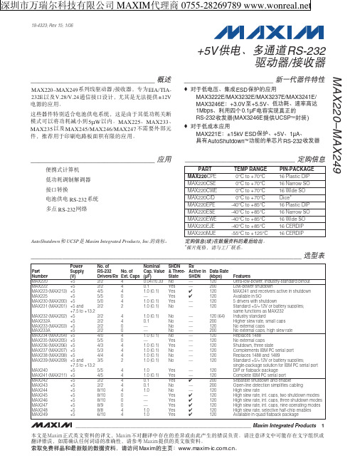
MAX220–MAX249࿅઼ഝڑಹ /ेฏಹLjከཛྷEIA/TIA232EჾࣆV.28/V.24ဳेਊහࣜLjᅐದกྐۨ໗ ޥ±12V ٫ᆚوᄮᅋă
ሦဗಹऔ໎Ӽคࠩ٫֠ޥ٫࿅༇Ljሦกᅑᅢದّڱߔࠞޢ ன৹ჾटࠞޢऋဏ ف5μW ჾăMAX225ĂMAX233Ă MAX235 ჾࣆ MAX245/MAX246/MAX247 ԥၖე༶ԩᆐ औLj༚ऌᅋᅢᄩฺ٫ଁғஎࢵᅘوᄮᅋă
1.0 (0.1) 0.1 — — 1.0 (0.1) — 1.0 (0.1) 1.0 (0.1) 1.0 (0.1) 1.0 (0.1)
1.0 1.0 (0.1) 0.1 0.1 1.0 — — — 1.0 1.0
SHDN & ThreeState No Yes Yes Yes Yes No
No No No No No Yes Yes No No No
_____________________________________________________________________ ၭျӹ
Part Number MAX220 MAX222 MAX223 (MAX213) MAX225 MAX230 (MAX200) MAX231 (MAX201)
MAX232 (MAX202) MAX232A MAX233 (MAX203) MAX233A MAX234 (MAX204) MAX235 (MAX205) MAX236 (MAX206) MAX237 (MAX207) MAX238 (MAX208) MAX239 (MAX209)
az7电气安全与防雷、防静电_pdf

7 电气安全与防雷、防静电7.1 电气安全工程7.2 静电安全工程7.3 防雷7.1 电气安全工程在化工生产中发生的电气事故,可以归纳为三个方面:①由于电气设备或电气线路的故障及损坏造成停电而导致的停产事故;②人身触电的伤亡事故;③由于电气原因,引起的火灾爆炸事故。
7.1.1 电气安全工程基础1. 触电事故原因触电事故是电流的能量直接或间接作用于人体造成的伤害。
发生触电事故的原因:缺乏电气安全知识。
违反操作规程。
电气设备不合格。
维修不善。
偶然因素。
2.触电事故的规律触电事故的季节性明显。
低压触电事故多于高压触电事故。
发生在线路部位触电事故较普遍。
误操作触电事故较多。
3. 触电事故的分类分为电击和电伤。
电击。
电击是电流通过人体内部,人体吸收局外能量受到的伤害。
主要伤害部位是心脏、中枢神经系统和肺部。
人体遭受数十毫安工频电流电击时,时间稍长即会致命。
电击是全身伤害,但一般不在人身表面留下大面积明显的伤痕。
电伤。
电伤是电流转变成其他形式的能量造成的人体伤害,包括电能转化成热能造成的电弧烧伤、灼伤和电能转化成化学能或机械能造成的电印记、皮肤金属化及机械损伤、电光眼等。
电伤多数是局部性伤害,在人身表面留有明显的伤痕。
4. 触电急救要点触电急救的要点是动作迅速,救护得法。
人触电以后,会出现神经麻痹、呼吸中断、心脏停止跳动等征象,外表上呈现昏迷不醒的状态,但不应该认为是死亡,而应该看作是“假死”,并且迅速而持久地进行抢救。
有触电者经4h甚至更长时间的紧急抢救而得救的事例。
据统计,从触电后1min开始救治者,90%有良好效果;从触电后6min开始救治者,10%有良好效果;而从触电后12min开始救治者,救活的可能性很小。
5.迅速脱离电源触电急救的首要措施。
(1)低压触电时使触电者脱离电源的方法①如果电源开关或电源插头在触电地点附近,可立即拉开开关或拔出插头,切断电源。
②如果电源开关或电源插头不在触电地点附近,可用有绝缘柄的电工钳或有干燥木柄的斧头切断电源线,断开电源;或用干木板等绝缘物插入触电者身下,隔断电源。
AZ AQUATAR家族产品系列介绍说明书

9F3C
1F3C
PFOS
CF2 CF2 CF2 SO3OH
CF2 CF2 CF2
PFOA
CF2 F3C
CF2 CF2 CF2
C8 Telomer
CF2 CF2 CF2 CH2CH2OH CF2 CF2 CF2 CF2
CF2
CF2
CF2
COOH
AZ Electronic Materials Confidential
(1.44/1.48/1.56)
(1.40/1.43/1.45)
AQUATAR-3S (1.42/1.44/1.49)
PFOS
AQUATAR-6 (1.40/1.43/1.45)
Fluoro Polymer
AQUATAR-8A (1.41/1.45/1.52)
AQUATAR-8B
for KrF “N” resist
4
AZ, the AZ logo, BARLi, Aquatar, nLOF, Kwik Strip, Klebosol, and S5pinfil are
registered trademarks and AX, DX, HERB, HiR, MiR, NCD, PLP, Signiflow,
SWG, and TARP are trademarks of AZ Electronic Materials.
SWG, and TARP are trademarks of AZ Electronic Materials.
2.4 Resist swing reduction effect in 365nm application
Substrate TARC Develop
: Silicon with HMDS(90C/60s) : 64nm FT, NO PAB : AZ 300MIF(2.38%) , puddle 60s
Comware V7无线控制器产品及特性介绍

重要
6
WX5500H系列规格
项目 尺寸 重量 工作温度 工作湿度 CPU 内存 CF FPGA 交流输入 直流输入 接口 无线转发性能 基础AP数量 最大管理AP数 量 最大支持无线用 户数 15.5KG 0℃~45℃ 5%~95%(非凝露) XLP416(1.4GHz@8 core) 32GB DDR3 4GB Altera 260*2 100V AC~240V AC; 50Hz/60Hz -48V DC~-60V DC 12个GE电口 12个SFP光口、4个SFP+光口 一个Console口 一个带外管理口 40Gbps(大包) 0(开局需要License) 1536 30K WX5540H 440mm×480mm×88.1mm TBD 0℃~45℃ 5%~95%(非凝露) XLP416(1.4GHz@8 core) 32GB DDR3 4GB Altera A9*1 100V AC~240V AC; 50Hz/60Hz -48V DC~-60V DC 8个GE电口 12个SFP+、4个QSFP+光口 一个Console口 一个带外管理口 100Gbps(大包) 0(开局需要License) 2048 40K WX5560H 440mm×480mm×88.1mm TBD 0℃~45℃ 5%~95%(非凝露) XLP432(1.4GHz@8 core) 32GB DDR3 4GB Altera A9*2 100V AC~240V AC; 50Hz/60Hz -48V DC~-60V DC 8个GE电口 12个SFP+、4个QSFP+光口 一个Console口 一个带外管理口 200Gbps(大包) 0(开局需要License) 2048 40K WX5580H 440mm×480mm×88.1mm
ADP2323 双通道、3 A、20 V同步降压调节器,集成高端MOSFET 数据手册说明书

典型应用电路INTVCC R TOP1C C1R C1C SS1C INTC DRVC IN1C BST1C BST2L1M1M2L2V INV INV OUT1C OUT1C OUT2V OUT2R BOT1R TOP2R C2C C2C SS2C IN2R BOT2R OSCF B 1C O M P 1S S 1E N 1P V I N 1B S T 1F B 2C O M P 2S S 2E N 2P V I N 2B S T 2MODE SCFG TRK2TRK1VDRV ADP2323GND PGOOD2PGOOD1SYNCRTSW1DL1PGND DL2SW209357-001图1.5055606570758085909510000.51.01.52.02.53.0E F F I C I E N C Y (%)OUTPUT CURRENT (A)V OUT = 5V V OUT = 3.3V09357-002图2.效率与输出电流的关系(V IN = 12 V ,f SW = 600 kHz)双通道、3 A 、20 V 同步降压调节器,集成高端MOSFET 数据手册ADP2323产品特性输入电压:4.5 V 至20 V 输出精度:±1%集成典型值90 mΩ的高端MOSFET 灵活的输出配置双路输出:3 A/3 A 单路交错式输出:6 A可编程开关频率:250 kHz 至1.2 MHz外部同步输入,可编程相移,或内部时钟输出可选PWM 或PFM 工作模式小型电感的限流可调外部补偿和软启动启动后进入预充电输出受ADIsimPower ™设计工具支持应用通信基础设施网络和服务器工业和仪器仪表医疗保健中间供电轨转换DC-DC 负载点应用概述ADP2323是一款功能全面的双通道降压DC-DC 调节器,采用电流模式架构。
ADP2323集成两个高端功率MOSFET 开关和两个低端驱动器,可控制外部的N 沟道MOSFET 。
DIODES贴片齐纳二极管AZ23C2V7选型手册
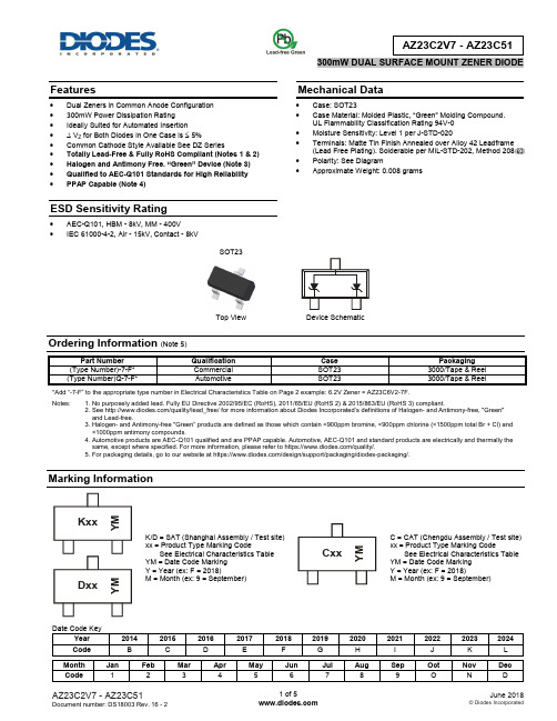
Features∙ Dual Zeners in Common Anode Configuration ∙ 300mW Power Dissipation Rating ∙ Ideally Suited for Automated Insertion ∙ ∆ V Z for Both Diodes in One Case is ≤ 5%∙ Common Cathode Style Available See DZ Series∙ Totally Lead-Free & Fully RoHS Compliant (Notes 1 & 2) ∙ Halogen and Antimony Free. “Green” Device (Note 3) ∙ Qualified to AEC-Q101 Standards for High Reliability ∙ PPAP Capable (Note 4)ESD Sensitivity Rating∙ AEC-Q101, HBM - 8kV, MM - 400V∙ IEC 61000-4-2, Air - 15kV, Contact - 8kVMechanical Data∙ Case: SOT23∙ Case Material: Molded Plastic , “Green” Molding Compound . UL Flammability Classification Rating 94V-0 ∙ Moisture Sensitivity: Level 1 per J-STD-020∙ Terminals: Matte Tin Finish Annealed over Alloy 42 Leadframe (Lead Free Plating). Solderable per MIL-STD-202, Method 208 ∙ Polarity: See Diagram∙Approximate Weight: 0.008 gramsOrdering Information (Note 5)*Add “-7-F” to the appropriate type number in Electrical Characteristics Table on Page 2 example: 6.2V Zener = AZ23C6V2-7F.Notes: 1. No purposely added lead. Fully EU Directive 2002/95/EC (RoHS), 2011/65/EU (RoHS 2) & 2015/863/EU (RoHS 3) compliant.2. See /quality/lead_free/ for more information about Diodes Incorporated’s definitions of Halogen - and Antimony-free, "Green" and Lead-free.3. Halogen- and Antimony-free "Green” products are defined as those which contain <900ppm bromine, <900ppm chlorine (<1500ppm total Br + Cl) and <1000ppm antimony compounds.4. Automotive products are AEC-Q101 qualified and are PPAP capable. Automotive, AEC-Q101 and standard products are electrically and thermally the same, except where specified. For more information, please refer to https:///quality/.5. For packaging details, go to our website at https:///design/support/packaging/diodes-packaging/.Marking InformationDevice SchematicK/D = SAT (Shanghai Assembly / Test site) xx = Product Type Marking CodeSee Electrical Characteristics Table YM = Date Code Marking Y = Year (ex: F = 2018)M = Month (ex: 9 = September)C = CAT (Chengdu Assembly / Test site) xx = Product Type Marking CodeSee Electrical Characteristics Table YM = Date Code Marking Y = Year (ex: F = 2018)M = Month (ex: 9 = September)CxxY MKxx Y MDxx Y MTop View SOT23Thermal CharacteristicsNote: 6. Mounted on FR-4 PC Board with recommended pad layout which can be found on our website at /package-outlines.html. Electrical Characteristics (@T A = +25°C, unless otherwise specified.)Note: 7. Short duration pulse test used to minimize self-heating effect.T , Ambient TA P , P O W E R D I S S I P A T I O N (m W )D 2001000400I , Z E N E R C U R R E N T (m A )Z V , ZENER VOLTAGE (V)Fig. 2 Typical Zener Breakdown Characteristics Z0102030I , Z E N E R C U R R E N T (m A )Z V , ZENER VOLTAGE (V)Fig. 3 Typical Zener Breakdown Characteristics Z 10203040I , Z E N E R C U R R E N T (m A )Z V , ZENER VOLTAGE (V)Fig. 4 Typical Zener Breakdown Characteristics ZC , T O T A L C A P A C I T A N C E (p F )T 1,000Fig. 5 Typical Total Capacitance vs. Nominal Zener VoltagePackage Outline DimensionsPlease see /package-outlines.html for the latest version.SOT23Suggested Pad LayoutPlease see /package-outlines.html for the latest version.SOT23。
- 1、下载文档前请自行甄别文档内容的完整性,平台不提供额外的编辑、内容补充、找答案等附加服务。
- 2、"仅部分预览"的文档,不可在线预览部分如存在完整性等问题,可反馈申请退款(可完整预览的文档不适用该条件!)。
- 3、如文档侵犯您的权益,请联系客服反馈,我们会尽快为您处理(人工客服工作时间:9:00-18:30)。
AZ23-V-SeriesDocument Number 85759Rev. 1.5, 24-Mar-06Vishay Semiconductors1Small Signal Zener Diodes, DualFeatures•These diodes are also available in other case styles and configurations including:the dual diode common cathode configu-ration with type designation DZ23, the sin-gle diode SOT23 case with the type designation BZX84C, and the single diodeSOD123 case with the type designation BZT52C. •Dual Silicon Planar Zener Diodes, Common Anode•The Zener voltages are graded according to the international E 24 standard•The parameters are valid for both diodes in one case. ΔV Z and Δr zj of the two diodes in one case is ≤ 5 %•Lead (Pb)-free component•Component in accordance to RoH S 2002/95/EC and WEEE 2002/96/ECMechanical DataCase: SOT23 Plastic case Weight: approx. 8.8 mgPackaging Codes/Options:GS18 / 10 k per 13" reel, (8 mm tape), 10 k/box GS08 / 3 k per 7" reel, (8 mm tape), 15 k/boxAbsolute Maximum RatingsT amb = 25°C, unless otherwise specified1) Device on fiberglass substrate, see layout on page 6Thermal CharacteristicsT amb = 25°C, unless otherwise specified1)Device on fiberglass substrate, see layout on page 6ParameterT est condition Symbol Value Unit Power dissipationP tot3001)mWParameterTest condition Symbol Value Unit Thermal resistance junction to ambient air R thJA 4201)K/W Junction temperature T j 150°C Storage temperature rangeT stg- 65 to + 150°C 2Document Number 85759Rev. 1.5, 24-Mar-06AZ23-V-SeriesVishay Semiconductors Electrical Characteristics1) Tested with pulses tp = 5 msPartnumberMarking CodeZener Voltage Range 1)Dynamic Resistance TestCurrent T emperature Coefficientof Zener VoltageReverse Voltage V Z at I ZTr zj at I ZT = 5 mA, f = 1 kHz r zj at I ZT = 1 mA, f = 1 kHzI ZTαVZ at I ZTV R at I R = 100 nAVΩmA10-4/°CVminmax min max AZ23C2V7-V D1 2.5 2.975 (< 83)< 5005- 9- 4-AZ23C3V0-V D2 2.8 3.280 (< 95)< 5005- 9- 3-AZ23C3V3-V D3 3.1 3.580 (< 95)< 5005- 8- 3-AZ23C3V6-V D4 3.4 3.880 (< 95)< 5005- 8- 3-AZ23C3V9-v D5 3.7 4.180 (< 95)< 5005- 7- 3-AZ23C4V3-V D64 4.680 (< 95)< 5005- 6- 1-AZ23C4V7-V D7 4.4570 (< 78)< 5005- 52-AZ23C5V1-V D8 4.8 5.430 (< 60)< 4805- 34> 0.8AZ23C5V6-V D9 5.2610 (< 40)< 4005- 26> 1AZ23C6V2-V D10 5.8 6.6 4.8 (< 10)< 2005- 17> 2AZ23C6V8-V D11 6.47.2 4.5 (< 8)< 150527> 3AZ23C7V5-V D1277.9 4 (< 7)< 505- 37> 5AZ23C8V2-V D137.78.7 4.5 (< 7)< 50547> 6AZ23C9V1-V D148.59.6 4.8 (< 10)< 50558> 7AZ23C10-V D159.410.6 5.2 (< 15)< 70558> 7.5AZ23C11-V D1610.411.6 6 (< 20)< 70559> 8.5AZ23C12-V D1711.412.77 (< 20)< 90569> 9AZ23C13-V D1812.414.19 (< 25)< 110579> 10AZ23C15-V D1913.815.611 (< 30)< 110579> 11AZ23C16-V D2015.317.113 (< 40)< 170589.5> 12AZ23C18-V D2116.819.118 (< 50)< 170589.5> 14AZ23C20-V D2218.821.220 (< 50)< 2205810> 15AZ23C22-V D2320.823.325 (< 55)< 2205810> 17AZ23C24-V D2422.825.628 (< 80)< 2205810> 18AZ23C27-V D2525.128.930 (< 80)< 2505810> 20AZ23C30-V D2******* (< 80)< 2505810> 22.5AZ23C33-V D2******* (< 80)< 2505810> 25AZ23C36-V D2******* (< 90)< 2505810> 27AZ23C39-V D2******* (< 90)< 30051012> 29AZ23C43-V D3******* (< 100)< 70051012> 32AZ23C47-V D3******* (< 100)< 75051012> 35AZ23C51-VD32485470 (< 100)< 75051012> 38AZ23-V-SeriesDocument Number 85759Rev. 1.5, 24-Mar-06Vishay Semiconductors3Electrical Characteristics1) Tested with pulses tp = 5 msPartnumberMarking CodeZener Voltage Range 1)Dynamic Resistance TestCurrent T emperature Coefficientof Zener VoltageReverse Voltage V Z at I ZTr zj at I ZT = 5 mA, f = 1 kHz r zj at I ZT = 1 mA, f = 1 kHzI ZTαVZ at I ZTV R at I R = 100 nAVΩmA10-4/°CVminmax min max AZ23B2V7-V D1 2.65 2.7575 (< 83)< 5005- 9- 4-AZ23B3V0-V D2 2.94 3.0680 (< 95)< 5005- 9- 3-AZ23B3V3-V D3 3.23 3.3780 (< 95)< 5005- 8- 3-AZ23B3V6-V D4 3.53 3.6780 (< 95)< 5005- 8- 3-AZ23B3V9-V D5 3.82 3.9880 (< 95)< 5005- 7- 3-AZ23B4V3-V D6 4.21 4.3980 (< 95)< 5005- 6- 1-AZ23B4V7-V D7 4.61 4.7970 (< 78)< 5005- 52-AZ23B5V1-V D85 5.230 (< 60)< 4805- 34> 0.8AZ23B5V6-V D9 5.49 5.7110 (< 40)< 4005- 26> 1AZ23B6V2-V D10 6.08 6.32 4.8 (< 10)< 2005- 17> 2AZ23B6V8-V D11 6.66 6.94 4.5 (< 8)< 150527> 3AZ23B7V5-V D127.357.65 4 (< 7)< 505- 37> 5AZ23B8V2-V D138.048.36 4.5 (< 7)< 50547> 6AZ23B9V1-V D148.929.28 4.8 (< 10)< 50558> 7AZ23B10-V D159.810.2 5.2 (< 15)< 70558> 7.5AZ23B11-V D1610.811.2 6 (< 20)< 70559> 8.5AZ23B12-V D1711.812.27 (< 20)< 90569> 9AZ23B13-V D1812.713.39 (< 25)< 110579> 10AZ23B15-V D1914.715.311 (< 30)< 110579> 11AZ23B16-V D2015.716.313 (< 40)< 170580.5> 12AZ23B18-V D2117.618.418 (< 50)< 170580.5> 14AZ23B20-V D2219.620.420 (< 50)< 2205810> 15AZ23B22-V D2321.622.425 (< 55)< 2205810> 17AZ23B24-V D2423.524.528 (< 80)< 2205810> 18AZ23B27-V D2526.527.530 (< 80)< 2505810> 20AZ23B30-V D2629.430.635 (< 80)< 2505810> 22.5AZ23B33-V D2732.333.740 (< 80)< 2505810> 25AZ23B36-V D2835.336.740 (< 90)< 2505810> 27AZ23B39-V D2938.239.850 (< 90)< 30051012> 29AZ23B43-V D3042.143.960 (< 100)< 70051012> 32AZ23B47-V D3146.147.970 (< 100)< 75051012> 35AZ23B51-VD32505270 (< 100)< 75051012> 38 4Document Number 85759Rev. 1.5, 24-Mar-06AZ23-V-SeriesVishay Semiconductors Typical CharacteristicsT amb = 25°C, unless otherwise specifiedFigure 1. Forward characteristicsFigure 2. Admissible Power Dissipation vs. Ambient Temperature Figure 3. Dynamic Resistance vs. Zener Current18114mA 10101010101010I FV F0.20.40.60.81V18115m W 4001000300200P totT am b100200 °C50018120103754327543210Ω0.123452345110 mAr zjI Z102Figure 4. Thermal Differential Resistance vs. Zener VoltageFigure 5. Dynamic Resistance vs. Zener VoltageFigure 6. Temperature Dependence of Zener Voltage vs. ZenerVoltage18121103543254321021r zth543210Ω12345234510100 VVZ at I Z = 5 mAnegati v e positi v e ΔΔV Z T jr zth = R thA x V Z x1812210075432754321Ωr10Tj = 25 °C I Z = 5 mA12345234510100 VV Z18123Δ2520151050- 5m V /°C ΔV Z T j12345234510100 VV ZAZ23-V-SeriesDocument Number 85759Rev. 1.5, 24-Mar-06Vishay Semiconductors5Figure 7. Change of Zener Voltage vs. Junction TemperatureFigure 8. Temperature Dependence of Zener Voltage vs. ZenerVoltageFigure9. Change of Zener Voltage vs. Junction Temperature181240.80.70.60.50.40.30.20.10 - 1- 0.2V ZVT j20406080100120140 CΔ18125Δ100806040200m V /°C ΔV Z T j20408060100 VV Z1812697531- 1V V 86420010060T j204012080140 °CFigure 10. Change of Zener voltage from turn-on up to the point ofthermal equilibrium vs. Zener voltageFigure 11. Change of Zener voltage from turn-on up to the point ofthermal equilibrium vs. Zener voltageFigure12. Breakdown Characteristics181271.61.20.80.40- 0.4V V 1.410.60.2 - 0.212345234510100 VV Z at I Z = 5 mAV Z = r zth x I ZΔ1812854321V V 020********* VV Z18111V ZmA 50403020100lz 6Document Number 85759Rev. 1.5, 24-Mar-06AZ23-V-SeriesVishay SemiconductorsLayout for R thJA testThickness: Fiberglass 0.059 in. (1.5 mm)Copper leads 0.012 in. (0.3 mm)Figure13. Breakdown Characteristics 18112102030040 V V Z mA 302010lzFigure 14. Breakdown Characteristics18113mA 1086420lz1020304050607080900100 VV ZAZ23-V-SeriesDocument Number 85759Rev. 1.5, 24-Mar-06Vishay Semiconductors7Package Dimensions in mm (Inches) 8Document Number 85759Rev. 1.5, 24-Mar-06AZ23-V-SeriesVishay SemiconductorsOzone Depleting Substances Policy StatementIt is the policy of Vishay Semiconductor GmbH to1.Meet all present and future national and international statutory requirements.2.Regularly and continuously improve the performance of our products, processes, distribution and operatingsystems with respect to their impact on the health and safety of our employees and the public, as well as their impact on the environment.It is particular concern to control or eliminate releases of those substances into the atmosphere which are known as ozone depleting substances (ODSs).The Montreal Protocol (1987) and its London Amendments (1990) intend to severely restrict the use of ODSs and forbid their use within the next ten years. Various national and international initiatives are pressing for an earlier ban on these substances.Vishay Semiconductor GmbH has been able to use its policy of continuous improvements to eliminate the use of ODSs listed in the following documents.1.Annex A, B and list of transitional substances of the Montreal Protocol and the London Amendmentsrespectively2.Class I and II ozone depleting substances in the Clean Air Act Amendments of 1990 by the EnvironmentalProtection Agency (EPA) in the USA3.Council Decision 88/540/EEC and 91/690/EEC Annex A, B and C (transitional substances) respectively. Vishay Semiconductor GmbH can certify that our semiconductors are not manufactured with ozone depleting substances and do not contain such substances.We reserve the right to make changes to improve technical designand may do so without further notice.Parameters can vary in different applications. All operating parameters must be validated for each customer application by the customer. Should the buyer use Vishay Semiconductors products for any unintended or unauthorized application, the buyer shall indemnify Vishay Semiconductors against all claims, costs, damages, and expenses, arising out of, directly or indirectly, any claim of personal damage, injury or death associated with such unintended or unauthorized use.Vishay Semiconductor GmbH, P.O.B. 3535, D-74025 Heilbronn, GermanyDocument Number: 91000Revision: 18-Jul-081DisclaimerLegal Disclaimer NoticeVishayAll product specifications and data are subject to change without notice.Vishay Intertechnology, Inc., its affiliates, agents, and employees, and all persons acting on its or their behalf (collectively, “Vishay”), disclaim any and all liability for any errors, inaccuracies or incompleteness contained herein or in any other disclosure relating to any product.Vishay disclaims any and all liability arising out of the use or application of any product described herein or of any information provided herein to the maximum extent permitted by law. The product specifications do not expand or otherwise modify Vishay’s terms and conditions of purchase, including but not limited to the warranty expressed therein, which apply to these products.No license, express or implied, by estoppel or otherwise, to any intellectual property rights is granted by this document or by any conduct of Vishay.The products shown herein are not designed for use in medical, life-saving, or life-sustaining applications unless otherwise expressly indicated. Customers using or selling Vishay products not expressly indicated for use in such applications do so entirely at their own risk and agree to fully indemnify Vishay for any damages arising or resulting from such use or sale. Please contact authorized Vishay personnel to obtain written terms and conditions regarding products designed for such applications.Product names and markings noted herein may be trademarks of their respective owners.元器件交易网。