MAX211ECAI-T中文资料
MAX产品后缀说明

MAX 产品后缀说明MAX 产品后缀说明三位后缀例: MAX1675E U A温度范围封装形式管脚数四位后缀另有一些MAXIM 产品后缀用四位表示,第一位表示产品精度等级;第二位表示温度范围:精度,后三位同三位后缀的IC.第三位表示封装形式;第四位表示产品管脚数。
例如:MAX631ACPA 第一个”A”表示5%的输出温度范围C 0°C - 70°C A -40°C - +125°CI -20°C - +85°C M -55 °C - +125°CE -40°C - +85°C封装形式A SSOP(密脚表面贴装)B CERQUAD(陶瓷方形封装)C TO220,TQFP(薄的四方表贴封装)D 陶瓷SB 封装E QSOP(四方表面贴封装)F 陶瓷Flat 封装H 模块SBGA 5*5TQFP J 陶瓷双列直插K SOT L LCCM MQFP(公制四方扁平封装) N 窄体陶瓷双列直插P 塑封DIP(双列直插) Q PLCCR 窄体陶瓷DIP S SO 表面贴封装T TO5,TO99,TO100 U TSSOP,uMAX,SOTV TO39 W 宽体SOX SC70 Y 窄SBZ TO92,MQUAD /D DICE(裸片)/PR 硬塑料/W 晶原管脚数A 8 N 18B 10,64 O 42C 12,192 P 20D 14 Q 2,100E 16 R 3,84F 22,256 S 4,80G 24 T 6,160H 44 U 38,60I 28 V 8(圆脚,隔离型)J 32 W 10(圆脚,隔离型)K 5,68 X 8L 40 Y 8(圆脚,隔离型)M 7,48 Z 10(圆脚,隔离型)。
MAX3301EETJ中文资料
General DescriptionThe MAX3301E/MAX3302E fully integrated USB On-the-Go (OTG) transceivers and charge pumps allow mobile devices such as PDAs, cellular phones, and digital cameras to interface directly with USB peripherals and each other without the need of a host PC. Use the MAX3301E/MAX3302E with an embedded USB host to directly connect to peripherals such as printers or external hard drives.The MAX3301E/MAX3302E integrate a USB OTG trans-ceiver, a V BUS charge pump, a linear regulator, and an I 2C-compatible, 2-wire serial interface. An internal level shifter allows the MAX3301E/MAX3302E to interface with +1.65V to +3.6V logic supply voltages. The MAX3301E/MAX3302E’s OTG-compliant charge pump operates with +3V to +4.5V input supply voltages, and supplies an OTG-compatible output on V BUS while sourcing more than 8mA of output current.The MAX3301E/MAX3302E enable USB OTG communi-cation from highly integrated digital devices that cannot supply or tolerate the +5V V BUS levels that USB OTG requires. The device supports USB OTG session-request protocol (SRP) and host-negotiation protocol (HNP).The MAX3301E/MAX3302E provide built-in ±15kV elec-trostatic-discharge (ESD) protection for the V BUS , ID_IN,D+, and D- terminals. The MAX3301E/MAX3302E are available in 25-bump chip-scale (UCSP™), 25-bump WLP package, 28-pin TQF N, and 32-pin TQF N pack-ages and operate over the extended -40°C to +85°C temperature range.ApplicationsMobile Phones Digital Cameras PDAsMP3 PlayersFeatureso USB 2.0-Compliant Full-/Low-Speed OTG Transceiverso Ideal for USB On-the-Go, Embedded Host, or Peripheral Deviceso ±15kV ESD Protection on ID_IN, V BUS , D+, and D-Terminalso Charge Pump for V BUS Signaling and Operation Down to 3Vo Internal V BUS and ID Comparatorso Internal Switchable Pullup and Pulldown Resistors for Host/Peripheral Functionality o I 2C Bus Interface with Command and Status Registerso Linear Regulator Powers Internal Circuitry and D+/D- Pullup Resistors o Support SRP and HNPMAX3301E/MAX3302EUSB On-the-Go Transceivers and Charge Pumps________________________________________________________________Maxim Integrated Products1Ordering Information19-3275; Rev 3; 10/07For pricing, delivery, and ordering information,please contact Maxim Direct at 1-888-629-4642,or visit Maxim’s website at .Note:All devices specified over the -40°C to +85°C operating range.‡UCSP bumps are in a 5 x 5 array. The UCSP package size is 2.5mm x 2.5mm x 0.62mm. Requires solder temperature profile described in the Absolute Maximum Ratings section. UCSP reli-ability is integrally linked to the user’s assembly methods, circuit board material and environment. See the UCSP Applications Information section of this data sheet for more information.*Future product—contact factory for availability.**EP = Exposed paddle.T = Tape and reel.+Denotes a lead-free package.Selector GuidePin Configurations appear at end of data sheet.M A X 3301E /M A X 3302EUSB On-the-Go Transceivers and Charge PumpsABSOLUTE MAXIMUM RATINGSDC ELECTRICAL CHARACTERISTICS(V CC = +3V to +4.5V, V L = +1.65V to +3.6V, C FLYING = 100nF, C VBUS = 1µF, ESR CVBUS = 0.1Ω(max), T A = T MIN to T MAX , unless otherwise noted. Typical values are at V CC = +3.7V, V L = +2.5V, T A = +25°C.) (Note 2)Note 1:The UCSP package is constructed using a unique set of packaging techniques that impose a limit on the thermal profile the device can be exposed to during board-level solder attach and rework. This limit permits only the use of the solder profiles recom-mended in the industry-standard specification, JEDEC 020A, paragraph 7.6, Table 3 for IR/VPR and convection reflow. Preheating is required. Hand or wave soldering is not allowed.Stresses beyond those listed under “Absolute Maximum Ratings” may cause permanent damage to the device. These are stress ratings only, and functional operation of the device at these or any other conditions beyond those indicated in the operational sections of the specifications is not implied. Exposure to absolute maximum rating conditions for extended periods may affect device reliability.All voltages are referenced to GND.V CC , V L .....................................................................-0.3V to +6V TRM (regulator off or supplied by V BUS )..-0.3V to (V BUS + 0.3V)TRM (regulator supplied by V CC )...............-0.3V to (V CC + 0.3V)D+, D- (transmitter tri-stated)...................................-0.3V to +6V D+, D- (transmitter functional)....................-0.3V to (V CC + 0.3V)V BUS .........................................................................-0.3V to +6V ID_IN, SCL, SDA.......................................................-0.3V to +6V INT , SPD, RESET , ADD, OE/INT , RCV, VP,VM, SUS, DAT_VP, SE0_VM ......................-0.3V to (V L + 0.3V)C+.............................................................-0.3V to (V BUS + 0.3V)C-................................................................-0.3V to (V CC + 0.3V)Short-Circuit Duration, V BUS to GND .........................ContinuousContinuous Power Dissipation (T A = +70°C)25-Bump WLP (derate 12.2mW/°C above +70°C).......976mW 25-Bump UCSP (derate 12.2mW/°C above +70°C)....976mW 32-Pin TQFN (5mm x 5mm x 0.8mm) (derate 21.3mW/°Cabove +70°C).........................................................1702mW 28-Pin TQFN (4mm x 4mm x 0.8mm) (derate 20.8mW/°Cabove +70°C).........................................................1666mW Operating Temperature Range ...........................-40°C to +85°C Junction Temperature......................................................+150°C Storage Temperature Range.............................-65°C to +150°C Lead Temperature (soldering, 10s).................................+300°C Bump Reflow Temperature (Note 1)Infrared (15s)...............................................................+200°C Vapor Phase (20s).......................................................+215°CM MMAX3301E/MAX3302EUSB On-the-Go Transceivers and Charge Pumps_______________________________________________________________________________________3DC ELECTRICAL CHARACTERISTICS (continued)(V CC = +3V to +4.5V, V L = +1.65V to +3.6V, C FLYING = 100nF, C VBUS = 1µF, ESR CVBUS = 0.1Ω(max), T A = T MIN to T MAX , unless otherwise noted. Typical values are at V CC = +3.7V, V L = +2.5V, T A = +25°C.) (Note 2)M A X 3301E /M A X 3302EUSB On-the-Go Transceivers and Charge Pumps 4_______________________________________________________________________________________DC ELECTRICAL CHARACTERISTICS (continued)(V CC = +3V to +4.5V, V L = +1.65V to +3.6V, C FLYING = 100nF, C VBUS = 1µF, ESR CVBUS = 0.1Ω(max), T A = T MIN to T MAX , unless otherwise noted. Typical values are at V CC = +3.7V, V L = +2.5V, T A = +25°C.) (Note 2)MAX3301E/MAX3302EUSB On-the-Go Transceivers and Charge Pumps_______________________________________________________________________________________5TIMING CHARACTERISTICSM A X 3301E /M A X 3302EUSB On-the-Go Transceivers and Charge Pumps 6_______________________________________________________________________________________I 2C-/SMBus™-COMPATIBLE TIMING SPECIFICATIONSNote 3:Guaranteed by bench characterization. Limits are not production tested.Note 4:A master device must provide a hold time of at least 300ns for the SDA signal to bridge the undefined region of SCL’s fallingedge.Note 5:C B is the total capacitance of one bus line in pF, tested with C B = 400pF.Note 6:Input filters on SDA, SCL, and ADD suppress noise spikes of less than 50ns.SMBus is a trademark of Intel Corporation.DRIVER PROPAGATION DELAY HIGH-TO-LOW(FULL-SPEED MODE)MAX3301E toc094ns/divD+1V/divD-1V/divDAT_VP 1V/divDRIVER PROPAGATION DELAY LOW-TO-HIGH(LOW-SPEED MODE)MAX3301E toc08100ns/divD-1V/divD+1V/div DAT_VP 1V/div DRIVER PROPAGATION DELAY HIGH-TO-LOW(LOW-SPEED MODE)MAX3301E toc07100ns/divD+1V/divD-1V/divDAT_VP 1V/div TIME TO EXIT SHUTDOWNMAX3301E toc054μs/div D-1V/divD+1V/divSCL 1V/divV BUS DURING SRP20ns/divV BUS 1V/divV BUS 1V/divC VBUS > 96μFC VBUS > 13μFTIME TO ENTER SHUTDOWNMAX3301E toc04100ns/div D+1V/div D-1V/div SCL 2V/div V BUS OUTPUT VOLTAGE vs. INPUT VOLTAGE (V CC )INPUT VOLTAGE (V CC ) (V)V B U S O U T P U T V O L T A G E (V )5.55.04.54.03.53.04.755.005.255.505.754.502.56.0V BUS OUTPUT VOLTAGE vs. VBUS OUTPUT CURRENTV BUS OUTPUT CURRENT (mA)V B U S O U T P U T V O L T A G E (V )2520151054.254.504.755.005.255.504.0030INPUT CURRENT (ICC )vs. V BUS OUTPUT CURRENTV BUS OUTPUT CURRENT (mA)I N P U T C U R R E N T (I C C ) (m A )16128410203040500020MAX3301E/MAX3302EUSB On-the-Go Transceivers and Charge Pumps_______________________________________________________________________________________7Typical Operating Characteristics(Typical operating circuit, V CC = +3.7V, V L = +2.5V, C FLYING = 100nF, T A = +25°C, unless otherwise noted.)SUPPLY CURRENT vs. TEMPERATURETEMPERATURE (°C)S U P P L Y C U R R E N T (m A )603510-150.20.40.60.81.00-4085DRIVER DISABLE DELAY (LOW-SPEED MODE)MAX3301E toc1410ns/divD+1V/divD-1V/divOE/INT 1V/divDRIVER ENABLE DELAY (LOW-SPEED MODE)MAX3301E toc13100ns/divD-1V/divD+1V/div C D+ = C D- = 400pFOE/INT 1V/divDRIVER DISABLE DELAY (FULL-SPEED MODE)MAX3301E toc1210ns/divD+1V/divD-1V/divOE/INT 1V/divDRIVER ENABLE DELAY (FULL-SPEED MODE)MAX3301E toc1110ns/divD-1V/divD+1V/div OE/INT 1V/divDRIVER PROPAGATION DELAY LOW-TO-HIGH(FULL-SPEED MODE)MAX3301E toc104ns/divD-1V/divD+1V/divDAT_VP 1V/div M A X 3301E /M A X 3302EUSB On-the-Go Transceivers and Charge Pumps 8_______________________________________________________________________________________Typical Operating Characteristics (continued)(Typical operating circuit, V CC = +3.7V, V L = +2.5V, C FLYING = 100nF, T A = +25°C, unless otherwise noted.)MAX3301E/MAX3302EUSB On-the-Go Transceivers and Charge PumpsM A X 3301E /M A X 3302EUSB On-the-Go Transceivers and Charge Pumps 10______________________________________________________________________________________Test Circuits and Timing DiagramsFigure 1. Load for Disable Time MeasurementFigure 2. Load for Enable Time, Transmitter Propagation Delay,and Transmitter Rise/Fall TimesMAX3301E/MAX3302EUSB On-the-Go Transceivers and Charge PumpsTest Circuits and Timing Diagrams (continued)Figure 6. Timing of DAT_VP, SE0_VM to D+, D- in VP_VM Mode (dat_se0 = 0)Figure 7. Timing of DAT_VP, SE0_VM to D+/D- in DAT_SE0Mode (dat_se0 = 1)Figure 8. Enable and Disable TimingFigure 9. D+/D- to RCV, DAT_VP, SE0_VM Propagation Delays(VP_VM Mode)Figure 10. D+/D- to DAT_VP, SE0_VM Propagation Delays (DAT_SE0 Mode)Figure 3. Load for Receiver Propagation Delay and Receiver Rise/Fall TimesFigure 4. Load for DAT_VP, SE0_VM Enable/Disable Time MeasurementsM A X 3301E /M A X 3302EUSB On-the-Go Transceivers and Charge Pumps Block DiagramFigure 11. Block DiagramMAX3301E/MAX3302EUSB On-the-Go Transceivers and Charge PumpsDetailed DescriptionThe USB OTG specification defines a dual-role USB device that acts either as an A device or as a B device.The A device supplies power on V BUS and initially serves as the USB host. The B device serves as the ini-tial peripheral and requires circuitry to monitor and pulse V BUS . These initial roles can be reversed using HNP.The MAX3301E/MAX3302E combine a low- and full-speed USB transceiver with additional circuitry required by a dual-role device. The MAX3301E/MAX3302E employ flexible switching circuitry to enable the device to act as a dedicated host or peripheral USB transceiv-er. For example, the charge pump can be turned off and the internal regulator can be powered from V BUS for bus-powered peripheral applications.The Selector Guide shows the differences between the MAX3301E and MAX3302E. The MAX3301E powers up in its lowest power state and must be turned on by set-ting the sdwn bit to 0. The MAX3302E powers up in the operational, VP/VM USB mode. This allows a micro-processor (µP) to use the USB port for power-on boot-up, without having to access I 2C. To put the MAX3302E into low-power shutdown, set the sdwn bit to 0. In the MAX3302E, special-function register 2 can be addressed at I 2C register location 10h, 11h (as well as locations 16h, 17h) to support USB OTG serial-interface engine (SIE) implementations that are limited to I 2C register addresses between 0h and 15h.TransceiverThe MAX3301E/MAX3302E transceiver complies with the USB version 2.0 specification, and operates at full-speed (12Mbps) and low-speed (1.5Mbps) data rates.Set the data rate with the SPD input. Set the direction of data transfer with the OE/INT input. Alternatively, control transceiver operation with control register 1 (Table 7)and special-function registers 1 and 2 (see Tables 14,15, and 16).Level ShiftersInternal level shifters allow the system-side interface to run at logic-supply voltages as low as +1.65V. Interface logic signals are referenced to the voltage applied to the logic-supply voltage, V L .Charge PumpThe MAX3301E/MAX3302E’s OTG-compliant charge pump operates with +3V to +4.5V input supply voltages (V CC ) and supplies a +4.8V to +5.25V OTG-compatible output on V BUS while sourcing the 8mA or greater out-put current that an A device is required to supply.Connect a 0.1µF flying capacitor between C+ and C-.Bypass V BUS to GND with a 1µF to 6.5µF capacitor, inaccordance with USB OTG specifications. The charge pump can be turned off to conserve power when not used. Control of the charge pump is set through the vbus_drv bit (bit 5) of control register 2 (see Table 8).Linear Regulator (TRM)An internal 3.3V linear regulator powers the transceiver and the internal 1.5k ΩD+/D- pullup resistor. Under the control of internal register bits, the linear regulator can be powered from V CC or V BUS . The regulator power-supply settings are controlled by the reg_sel bit (bit 3) in special-function register 2 (Tables 15 and 16). This flexibility allows the system designer to configure the MAX3301E/MAX3302E for virtually any USB power situation.The output of the TRM is not a power supply. Do not use as a power source for any external circuitry. Connect a 1.0µF (or greater) ceramic or plastic capacitor from TRM to GND, as close to the device as possible.V BUS Level-Detection ComparatorsComparators drive interrupt source register bits 0, 1,and 7 (Table 10) to indicate important USB OTG V BUS voltage levels:•V BUS is valid (vbus_vld)•USB session is valid (sess_vld)•USB session has ended (sess_end)The vbus_valid comparator sets vbus_vld to 1 if V BUS is higher than the V BUS valid comparator threshold. The V BUS valid status bit (vbus_vld) is used by the A device to determine if the B device is sinking too much current (i.e., is not supported). The session_valid comparator sets sess_vld to 1 if V BUS is higher than the session valid comparator threshold. This status bit indicates that a data transfer session is valid. The session_end com-parator sets sess_end to 1 if V BUS is higher than theFigure 12. Comparator Network DiagramM A X 3301E /M A X 3302EUSB On-the-Go Transceivers and Charge Pumpssession end comparator threshold. Figure 12 shows the level-detector comparators. The interrupt-enable regis-ters (Tables 12 and 13) determine whether a falling or rising edge of V BUS asserts these status bits.ID_INThe USB OTG specification defines an ID input that determines which dual-role device is the default host.An OTG cable connects ID to ground in the connector of one end and is left unconnected in the other end.Whichever dual-role device receives the grounded end becomes the A device. The MAX3301E/MAX3302E pro-vide an internal pullup resistor on ID_IN. Internal com-parators detect if ID_IN is grounded or left floating.Interrupt LogicWhen OTG events require action, the MAX3301E/MAX3302E provide an interrupt output signal on INT .Alternatively, OE/INT can be configured to act as an interrupt output while the device operates in USB sus-pend mode. Program INT and OE/INT as open-drain or push-pull interrupts with irq_mode (bit 1 of special-func-tion register 2, see Tables 15 and 16).V BUS Power ControlV BUS is a dual-function port that powers the USB bus and/or provides a power source for the internal linear reg-ulator. The V BUS power-control block performs the various switching functions required by an OTG dual-role device.These actions are programmed by the system logic using bits 5 to 7 of control register 2 (see Table 8) to:•Discharge V BUS through a resistor•Provide power-on or receive power from V BUS •Charge V BUS through a resistorThe OTG supplement allows an A device to turn V BUS off when the bus is not being used to conserve power.The B device can issue a request that a new session be started using SRP. The B device must discharge V BUS to a level below the session-end threshold (0.8V) to ensure that no session is in progress before initiating SRP. Setting bit 6 of control register 2 to 1, discharges V BUS to GND through a 5k Ωcurrent-limiting resistor.When V BUS has discharged, the resistor is removed from the circuit by resetting bit 6 of control register 2. An OTG A device is required to supply power on V BUS .The MAX3301E/MAX3302E provide power to V BUS from V CC or from the internal charge pump. Set bit 5 in control register 2 to 1 in both cases. Bit 5 in control register 2controls a current-limited switch, preventing damage to the device in the event of a V BUS short circuit.An OTG B device (peripheral mode) can request a ses-sion using SRP. One of the steps in implementing SRP requires pulsing V BUS high for a controlled time. A 930Ωresistor limits the current according to the OTG specifi-cation. Pulse V BUS through the pullup resistor by assert-ing bit 7 of control register 2. Prior to pulsing V BUS (bit 7), a B device first connects an internal pulldown resis-tor to discharge V BUS below the session-end threshold.The discharge current is limited by the 5k Ωresistor and set by bit 6 of control register 2. An OTG A device mustMAX3301E/MAX3302EUSB On-the-Go Transceivers and Charge Pumpssupply 5V power and at least 8mA on V BUS . Setting bit 5 of control register 2 turns on the V BUS charge pump.Operating ModesThe MAX3301E/MAX3302E have four operating modes to optimize power consumption. Only the I 2C interface remains active in shutdown mode, reducing supply cur-rent to 1µA. The I 2C interface, the ID_IN port, and the session-valid comparator all remain active in interrupt shutdown mode. RCV asserts low in suspend mode; how-ever, all other circuitry remains active. Table 1 lists the active blocks’ power in each of the operating modes.Applications InformationData TransferTransmitting Data to the USBThe MAX3301E/MAX3302E transceiver features two modes of transmission: DAT_SE0 or VP_VM (see Table 3).Set the transmitting mode with dat_se0 (bit 2 in control register 1, see Table 7). In DAT_SE0 mode with OE/INT low, DAT_VP specifies data for the differential transceiv-er, and SE0_VM forces D+/D- to the single-ended zero (SE0) state. In VP_VM mode with OE/INT low, DAT_VP drives D+, and SE0_VM drives D-. The differential receiver determines the state of RCV.Receiving Data from the USBThe MAX3301E/MAX3302E transceiver features two modes of receiving data: DAT_SE0 or VP_VM (see Table 4). Set the receiving mode with dat_se0 (bit 2 in control register 1, see Table 7). In DAT_SE0 mode with OE/INT high, DAT_VP is the output of the differential receiver and SE0_VM indicates that D+ and D- are both logic-low. In VP_VM mode with OE/INT high, DAT_VP provides the input logic level of D+ and SE0_VM pro-vides the input logic level of D-. The differential receiver determines the state of RCV. VP and VM echo D+ and D-, respectively.OE/INTOE/INT controls the direction of communication. OE/INT can also be programmed to act as an interrupt output when in suspend mode. The output-enable portion con-trols the input or output status of DAT_VP/SE0_VM and D+/D-. When OE/INT is a logic 0, DAT_VP and SE0_VM function as inputs to the D+ and D- outputs in a method depending on the status of dat_se0 (bit 2 in control reg-ister 1). When OE/INT is a logic 1, DAT_VP and SE0_VM indicate the activity of D+ and D-.OE/INT functions as an interrupt output when the MAX3301E/MAX3302E is in suspend mode and oe_int_en = 1 (bit 5 in control register 1, see Table 7). Inthis mode, OE/INT detects the same interrupts as INT .Set irq_mode (bit 1 in special-function register 2, see Tables 15 and 16) to 0 to program OE/INT as an open-drain interrupt output. Set irq_mode to 1 to configure OE/INT as a push-pull interrupt output.RCVRCV monitors D+ and D- when receiving data. RCV is a logic 1 for D+ high and D- low. RCV is a logic 0 for D+low and D- high. RCV retains its last valid state when D+and D- are both low (single-ended zero, or SE0). RCV asserts low in suspend mode. Table 4 shows the state of RCV.SPDUse hardware or software to control the slew rate of the D+ and D- terminals. The SPD input sets the slew rate of the MAX3301E/MAX3302E when spd_susp_ctl (bit 1 in special-function register 1, see Table 14) is 0. Drive SPD low to select low-speed mode (1.5Mbps). Drive SPD high to select full-speed mode (12Mbps). Alternatively,when spd_susp_ctl (bit 1 of special-function register 1)is 1, software controls the slew rate. The SPD input is ignored when using software to control the data rate.The speed bit (bit 0 of control register 1, see Table 7)sets the slew rate when spd_susp_ctl = 1.SUSUse hardware or software to control the suspend mode of the MAX3301E/MAX3302E. Set spd_susp_ctl (bit 1 of special-function register 1, see Table 14) to 0 to allow the SUS input to enable and disable the suspend mode of the MAX3301E/MAX3302E. Drive SUS low for normal operation. Drive SUS high to enable suspend mode.RCV asserts low in suspend mode while all other circuit-ry remains active.Alternatively, when the spd_susp_ctl bit (bit 1 of special-function register 1) is set to 1, software controls the sus-pend mode. Set the suspend bit (bit 1 of control register 1, see Table 7) to 1 to enable suspend mode. Set the suspend bit to 0 to resume normal operation. The SUS input is ignored when using software to control suspend mode. The MAX3301E/MAX3302E must be in full-speed mode (SPD = high or speed = 1) to issue a remote wake-up from the device when in suspend mode. RESETThe active-low RESET input allows the MAX3301E/MAX3302E to be asynchronously reset without cycling the power supply. Drive RESET low to reset the internal registers (see Tables 7–16 for the default power-up states). Drive RESET high for normal operation.M A X 3301E /M A X 3302EUSB On-the-Go Transceivers and Charge Pumps 2-Wire I 2C-Compatible Serial InterfaceA register file controls the various internal switches and operating modes of the MAX3301E/MAX3302E through a simple 2-wire interface operating at clock rates up to 400kHz. This interface supports data bursting, where multiple data phases can follow a single address phase.UART ModeSet uart_en (bit 6 in control register 1) to 1 to place the MAX3301E/MAX3302E in UART mode. D+ transfers data to DAT_VP and SE0_VM transfers data to D- in UART mode.General-Purpose Buffer ModeSet gp_en (bit 7 in special-function register 1) and dat_se0 (bit 2 in control register 1) to 1, set uart_en (bit 6in control register 1) to 0, and drive OE/INT low to place the MAX3301E/MAX3302E in general-purpose buffer mode. Control the direction of data transfer with dmi-nus_dir and dplus_dir (bits 3 and 4 of special-function register 1, see Tables 2 and 14).Serial AddressingThe MAX3301E/MAX3302E operate as a slave device that sends and receives control and status signals through an I 2C-compatible 2-wire interface. The inter-face uses a serial data line (SDA) and a serial clock line (SCL) to achieve bidirectional communication between master(s) and slave(s). A master (typically a microcon-troller) initiates all data transfers to and from the MAX3301E/MAX3302E and generates the SCL clock that synchronizes the data transfer (Figure 13).The MAX3301E/MAX3302E SDA line operates as both an input and as an open-drain output. SDA requires aMAX3302E SCL line only operates as an input. SCL requires a pullup resistor if there are multiple masters on the 2-wire interface, or if the master in a single-master system has an open-drain SCL output.Each transmission consists of a start condition (see F igure 14) sent by a master device, the MAX3301E/MAX3302E 7-bit slave address (determined by the state of ADD), plus an R/W bit (see F igure 15), a register address byte, one or more data bytes, and a stop condi-tion (see Figure 14).Figure 13. 2-Wire Serial-Interface Timing DetailsMAX3301E/MAX3302EUSB On-the-Go Transceivers and Charge PumpsFigure 14. Start and Stop ConditionsFigure 15. Slave AddressM A X 3301E /M A X 3302EUSB On-the-Go Transceivers and Charge PumpsNote 7:Enter suspend mode by driving SUS high or by writing a 1 to suspend (bit 1 in control register 1), depending on the status of spd_susp_ctl in special-function register 1.X = Don’t care.MAX3301E/MAX3302EUSB On-the-Go Transceivers and Charge PumpsStart and Stop ConditionsBoth SCL and SDA assert high when the interface is not busy. A master device signals the beginning of a trans-mission with a start (S) condition by transitioning SDA from high to low while SCL is high. The master issues a stop (P) condition by transitioning SDA from low to high while SCL is high. The bus is then free for another trans-mission (see Figure 14).Bit TransferOne data bit is transferred during each clock pulse. The data on SDA must remain stable while SCL is high (see Figure 16).AcknowledgeThe acknowledge bit (ACK) is the 9th bit attached to any 8-bit data word. ACK is always generated by the receiving device. The MAX3301E/MAX3302E generatean ACK when receiving an address or data by pulling SDA low during the ninth clock period. When transmit-ting data, the MAX3301E/MAX3302E wait for the receiv-ing device to generate an ACK. Monitoring ACK allows for detection of unsuccessful data transfers. An unsuc-cessful data transfer occurs if a receiving device is busy or if a system fault has occurred. In the event of an unsuccessful data transfer, the bus master should reat-tempt communication at a later time.Slave AddressA bus master initiates communication with a slave device by issuing a START condition followed by the 7-bit slave address (see F igure 15). When idle, the MAX3301E/MAX3302E wait for a START condition fol-lowed by its slave address. The LSB of the address word is the read/write (R/W ) bit. R/W indicates whether the master is writing to or reading from the MAX3301E/MAX3302E (R/W = 0 selects the write con-dition, R/W = 1 selects the read condition). After receiving the proper address, the MAX3301E/MAX3302E issue an ACK.The MAX3301E/MAX3302E have two possible addresses (see Table 5). Address bits A6 through A1 are preset,while a reset condition or an I 2C general call address loads the value of A0 from ADD. Connect ADD to GND to set A0 to 0. Connect ADD to V L to set A0 to 1. This allows up to two MAX3301E’s or two MAX3302E’s to share the same bus.Write Byte FormatWriting data to the MAX3301E/MAX3302E requires the transmission of at least 3 bytes. The first byte consists of the MAX3301E/MAX3302E’s 7-bit slave address, fol-lowed by a 0 (R/W bit). The second byte determines which register is to be written to. The third byte is the new data for the selected register. Subsequent bytes are data for sequential registers. F igure 18 shows the typical write byte format.Read Byte FormatReading data from the MAX3301E/MAX3302E requires the transmission of at least 3 bytes. The first byte con-sists of the MAX3301E/MAX3302E’s slave address, fol-lowed by a 0 (R/W bit). The second byte selects the register from which data is read. The third byte consistsFigure 16. Bit TransferFigure 17. Acknowledge。
MAX213CAI-T中文资料

General DescriptionThe MAX200–MAX211/MAX213 transceivers are designed for RS-232 and V.28 communication inter-faces where ±12V supplies are not available. On-board charge pumps convert the +5V input to the ±10V need-ed for RS-232 output levels. The MAX201 and MAX209operate from +5V and +12V, and contain a +12V to -12V charge-pump voltage converter.The MAX200–MAX211/MAX213 drivers and receivers meet all EIA/TIA-232E and CCITT V.28 specifications at a data rate of 20kbps. The drivers maintain the ±5V EIA/TIA-232E output signal levels at data rates in excess of 120kbps when loaded in accordance with the EIA/TIA-232E specification.The 5µW shutdown mode of the MAX200, MAX205,MAX206, and MAX211 conserves energy in battery-powered systems. The MAX213 has an active-low shut-down and an active-high receiver enable control. Two receivers of the MAX213 are active, allowing ring indica-tor (RI) to be monitored easily using only 75µW power.The MAX211 and MAX213 are available in a 28-pin wide small-outline (SO) package and a 28-pin shrink small-outline (SSOP) package, which occupies only 40% of the area of the SO. The MAX207 is now avail-able in a 24-pin SO package and a 24-pin SSOP. The MAX203 and MAX205 use no external components,and are recommended for applications with limited circuit board space.ApplicationsComputersLaptops, Palmtops, Notebooks Battery-Powered Equipment Hand-Held Equipment Next-Generation Device Features ♦For Low-Cost Applications:MAX221E: ±15kV ESD-Protected, +5V, 1µA, Single RS-232 Transceiver with AutoShutdown™♦For Low-Voltage and Space-Constrained Applications:MAX3222E/MAX3232E/MAX3237E/MAX3241E/MAX3246E: ±15kV ESD-Protected, Down to 10nA,+3.0V to +5.5V, Up to 1Mbps, True RS-232Transceivers (MAX3246E Available in UCSP™Package)♦For Space-Constrained Applications:MAX3228E/MAX3229E: ±15kV ESD-Protected,+2.5V to +5.5V, RS-232 Transceivers in UCSP ♦For Low-Voltage or Data Cable Applications:MAX3380E/MAX3381E: +2.35V TO +5.5V, 1µA,2Tx/2Rx RS-232 Transceivers with ±15kV ESD-Protected I/O and Logic Pins ♦For Low-Power Applications:MAX3224E–MAX3227E/MAX3244E/MAX3245E:±15kV ESD-Protected, 1µA, 1Mbps, +3.0V to+5.5V, RS-232 Transceivers with AutoShutdown Plus™MAX200–MAX211/MAX213+5V , RS-232 Transceivers with 0.1µF External Capacitors ________________________________________________________________Maxim Integrated Products 119-0065; Rev 6; 10/03For pricing, delivery, and ordering information,please contact Maxim/Dallas Direct!at 1-888-629-4642, or visit Maxim’s website at .Ordering Information appears at end of data sheetAutoShutdown, AutoShutdown Plus, and UCSP are trademarks of Maxim Integrated Products, Inc.MAX200–MAX211/MAX213+5V , RS-232 Transceiverswith 0.1µF External Capacitors______________________________________________________________________________________19Ordering Information*Contact factory for dice specifications.M A X 200–M A X 211/M A X 213+5V , RS-232 Transceiverswith 0.1µF External Capacitors Maxim cannot assume responsibility for use of any circuitry other than circuitry entirely embodied in a Maxim product. No circuit patent licenses are implied. Maxim reserves the right to change the circuitry and specifications without notice at any time.20____________________Maxim Integrated Products, 120 San Gabriel Drive, Sunnyvale, CA 94086 408-737-7600©2003 Maxim Integrated ProductsPrinted USAis a registered trademark of Maxim Integrated Products.Package Information(The package drawing(s) in this data sheet may not reflect the most current specifications. For the latest package outline information,go to /packages .)。
MAX1722EZK-T中文资料
MAX1722
FB 3
4
OUT
THIN SOT23-5
Pin Configurations are continued at end of data sheet.
________________________________________________________________ Maxim Integrated Products
元器件交易网
19-1735; Rev 0; 7/01
1.5µA IQ, Step-Up DC-DC Converters in Thin SOT23-5
General Description
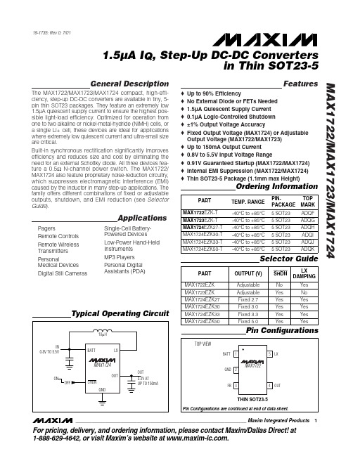
The MAX1722/MAX1723/MAX1724 compact, high-efficiency, step-up DC-DC converters are available in tiny, 5pin thin SOT23 packages. They feature an extremely low 1.5µA quiescent supply current to ensure the highest possible light-load efficiency. Optimized for operation from one to two alkaline or nickel-metal-hydride (NiMH) cells, or a single Li+ cell, these devices are ideal for applications where extremely low quiescent current and ultra-small size are critical. Built-in synchronous rectification significantly improves efficiency and reduces size and cost by eliminating the need for an external Schottky diode. All three devices feature a 0.5Ω N-channel power switch. The MAX1722/ MAX1724 also feature proprietary noise-reduction circuitry, which suppresses electromagnetic interference (EMI) caused by the inductor in many step-up applications. The family offers different combinations of fixed or adjustable outputs, shutdown, and EMI reduction (see Selector Guide). o o o o o o o o o o o
FM-I211AT-T1 千兆电口网卡 说明书
本手册所有内容,其版权属于北京东大金智科技有限公司(以下简称东大金智)所有,未经北京东大金智科技有限公司许可,任何单位和个人不得仿制,拷贝,转译或者任意引用。
版权所有不得翻印北京东大金智科技有限公司1.产品介绍●Product Description飞迈瑞克FM-I211AT-T1是一款基于Intel I211芯片的千兆以太网电口网卡,它具有1个1GbE的RJ45接口,可支持1000mbps的传输带宽,同时支持PCI-E X1标准插槽,保证了网卡高效、稳定的工作。
另外网卡还支持VLAN、QOS策略、流量控制等功能,适合中大型局域网的应用。
2.产品特性●Product Description●支持100M/1GGbps单个RJ45接口;●接口标准支持PCI Express 2.0;●低成本,低功耗,节能以太网和DMA合并。
●具有集成MAC和PHY的单端口2500MBASE-T控制器2500Mbps以太网网络过渡3.操作系统支持●Operating System Support4.基本参数●Basic parameters5.技术参数●Technical Parameters6.产品规格●Product Size7.产品图片●Product pictures8.订购信息●Ordering Information9.配套清单●Supporting list1.以太网网卡2. 合格证3. 保修卡4. 光模块(选配)5. 驱动光盘1张(选配)6. 1U支架1块(标配2U支架)10.安装连接●Installation connection为保证以太网适配器能够正确安装请您按照以下步骤进行。
1. 关闭计算机。
2. 断开电源电缆。
3. 卸下主机盖并找到闲置的PCI-E(X8、X16)总线扩展槽。
4. 通过卸下螺丝钉或松开拉杆拔出插槽盖板(如果有)。
5. 抓住以太网适配器的顶部边缘并将其牢固地插入卡槽。
6. 使用现有的螺钉或拉杆重新固定以太网适配器的固定支架。
Turck双检测面电感式传感器说明书

T 04:44:13+02:00型号NI4-DSU35TC-2Y1X2/S1176货号1051018额定工作距离Sn 4 mm 安装方式非齐平修正系数37#钢 = 1; 铝 = 0.3; 不锈钢= 0.7; 黄铜 = 0.4重复精度ð 2 满量程的 %温度漂移10 %磁滞1…10 %环境温度-25…+70 °C 输出性能4线, NAMUR 阀控制Exi (max. 30 V)开关频率0.05 kHz电压Nom. 8.2 VDC 无激励电流损耗ï 2.1 mA 激励电流损耗ð 1.2 mA认证依据KEMA 02 ATEX 1090X 内置 电感(L ) / 电容 (C )150 nF / 150 µH防爆标志防爆标识为II 2 G/Ex ia IIC T6 Gb /II 1 D Ex ia D 20T95 °C Da(最大 U = 20 V, I = 60 mA, P = 200 mW)警告防静电设计用于阀位回讯检测的双检测面电感式传感器, DSU35尺寸62 x 60 x 35 mm外壳材料塑料, 塑料, PA12-GF20, 黄感应面材料塑料, 塑料, PA12-GF20, 黑连接接线端子夹紧能力ð 2.5 mm 防震动性55 Hz (1 mm)防冲击性30 g (11 ms)防护等级IP67开关状态指示2路LED指示灯 黄/黄可供货2个导线密封套(蓝),2个导线密封套的密封圈,1个M20x1密封塞,1个商标sATEX 防爆认证II 组设备,设备等级2G. 可用于气体危险1区sATEX 防爆认证,II组设备,可应用于粉尘危险0区s 满足SIL2和IEC61508标准s 长方形,外壳类型DSU35s 塑料, PP -GF30-V0s 检测旋转执行器位置两路输出s 在标准执行器上安装s 不锈钢材质的快插和螺纹拧接的插头s 2线直流, nom. 8.2 VDCs输出遵循本安型DIN EN 60947-5-6标准(NAMUR)s接线端子接线图功能原理电感式传感器以无磨损和非接触的方式来检测金属物体 阀位回讯是专为旋转执行器的位置检测而设计的 它将非接触式电感传感器的可靠性与模块化的外壳系统的灵活性结合起来。
01_CAM211综合测控保护装置说明书(V3.0)

CAN2000变电站综合自动化系统CAM211综合测控装置技术使用说明书(V3.0)山东鲁能积成电子股份有限公司2003年8月关于CAN2000变电站综合自动化系统的所有技术和使用说明书的版权为山东鲁能积成电子股份有限公司所有。
山东鲁能积成电子股份有限公司保留对所有资料的修改和解释权。
目录1 CAM211综合测控装置 (1)1.1 交流模拟量采集 (1)1.2 开关量采集 (1)1.3 直流模拟量采集 (1)1.4 脉冲量采集 (1)1.5 控制输出及操作 (1)CAM211综合测控装置背板端子接线图CAM211综合测控装置原理接线展开图1 CAM211综合测控装置CAM211装置设计有完整的测量和控制功能,可以完成对一台断路器的交流模拟量的采集及其分合控制,同时,还设计有开关量采集、直流模拟量采集、脉冲量的采集等。
1.1 交流模拟量采集装置以三表法测量一个断路器的电流、电压、有功、无功、功率因数和频率等量。
装置采用自跟踪、自校准、自补偿、免调节技术,测量精度高,使用方便。
被测模拟量如下:三表法:(仅A、C两相CT时,将CT的In按-Ib接入装置即可)直接采集量:Ua、Ub、Uc、Ia、Ib、Ic、3U0软件计算量:Uab、Ubc、Uca、P、Q、cos、fCAM211交流电压可选择100V或300V输入。
1.2 开关量采集开关量采集共有16路,装置本身使用了6路,外部10路用于其它开关量的采集。
装置本身所用6路通道(0-5),分别用于操作回路的合闸位置信号、跳闸位置信号、合后位置信号的采集等;外部输入信号除6被固定为远方位置外,其它可以任意定义。
1.3直流模拟量采集装置同时设计了两路直流模拟量测量功能,增加了装置的配置灵活性,扩大了装置的应用范围。
1.4 脉冲量采集装置设计了两路脉冲量输入接口,可以采集一条线路的有功电度和无功电度。
脉冲电源为24VDC,可由本装置提供,也可由电度表提供。
1.5 控制输出及操作装置提供一个断路器的手动及遥控分合控制功能及三相操作功能。
AXIS 211 211A 网络摄像机 说明书

认证
EMC: EN55024:1998 + A1 + A2, EN55022: 1998 + A1 Class B, EN61000-3-2:2000, EN61000-3-3:1995 + A1, FCC Part 15 Subpart B Class B by compliance with EN55022:1998 Class B, VCCI:2003 Class B ITE, C-tick AS/NZS 3548, Canadian ICES-003 B by compliance with EN55022:1998 Class B Safety: EN60950, UL, CSA
包含附件
9 V DC电源, 支架, 接线工具, 安装指南, 包含安装工具, 软件和用户手册的CD, MPEG-4使用许可 (1个编码器, 1个解码器), MPEG-4解码器(Windows)
其他附件 (未包含在产品包装中)
用于室外或恶劣环境下的防护罩 Power over Ethernet 中跨 AXIS 292 网络视频解码器 AXIS MPEG-4 解码器使用许可10用户套装
内置多窗口移动侦测功能, 具备外部I/O接口, 支持触发 型事件和计划型事件,并提供多种报警通知机制, 具 备报警前后缓存, AXIS 211: 1.2 MB (320 x 240, 4 fps条件 下约可存储40秒钟录像), AXIS 211A: 9 MB (同样条件下 约可存储5分钟录像)
Ethernet 10BaseT/100BaseTX, RJ-45 接线模块提供I/O接口(1路报警输入, 1路报警输出) 及 辅助电源连接 AXIS 211A: 3.5 mm麦克接口(max 270 mVpp)或单声 道线路输入(max 3.2 Vpp), 用于连接有源扬声器的3.5 mm单声道线路输出接口(max 3.0 Vpp)
- 1、下载文档前请自行甄别文档内容的完整性,平台不提供额外的编辑、内容补充、找答案等附加服务。
- 2、"仅部分预览"的文档,不可在线预览部分如存在完整性等问题,可反馈申请退款(可完整预览的文档不适用该条件!)。
- 3、如文档侵犯您的权益,请联系客服反馈,我们会尽快为您处理(人工客服工作时间:9:00-18:30)。
________________________________________________________________Maxim Integrated Products 1General DescriptionThe MAX202E–MAX213E, MAX232E/MAX241E line drivers/receivers are designed for RS-232 and V.28communications in harsh environments. Each transmitter output and receiver input is protected against ±15kV electrostatic discharge (ESD) shocks, without latchup.The various combinations of features are outlined in the Selector Guide.The drivers and receivers for all ten devices meet all EIA/TIA-232E and CCITT V.28specifications at data rates up to 120kbps, when loaded in accordance with the EIA/TIA-232E specification.The MAX211E/MAX213E/MAX241E are available in 28-pin SO packages, as well as a 28-pin SSOP that uses 60% less board space. The MAX202E/MAX232E come in 16-pin TSSOP, narrow SO, wide SO, and DIP packages. The MAX203E comes in a 20-pin DIP/SO package, and needs no external charge-pump capacitors. The MAX205E comes in a 24-pin wide DIP package, and also eliminates external charge-pump capacitors. The MAX206E/MAX207E/MAX208E come in 24-pin SO, SSOP, and narrow DIP packages. The MAX232E/MAX241E operate with four 1µF capacitors,while the MAX202E/MAX206E/MAX207E/MAX208E/MAX211E/MAX213E operate with four 0.1µF capacitors,further reducing cost and board space.________________________ApplicationsNotebook, Subnotebook, and Palmtop Computers Battery-Powered Equipment Hand-Held EquipmentNext-Generation Device Featureso For Low-Voltage ApplicationsMAX3222E/MAX3232E/MAX3237E/MAX3241E/MAX3246E: ±15kV ESD-Protected Down to10nA, +3.0V to +5.5V, Up to 1Mbps, True RS-232Transceivers (MAX3246E Available in a UCSP™Package)o For Low-Power ApplicationsMAX3221/MAX3223/MAX3243: 1µA SupplyCurrent, True +3V to +5.5V RS-232 Transceivers with Auto-Shutdown™o For Space-Constrained ApplicationsMAX3233E/MAX3235E: ±15kV ESD-Protected,1µA, 250kbps, +3.0V/+5.5V, Dual RS-232Transceivers with Internal Capacitorso For Low-Voltage or Data Cable ApplicationsMAX3380E/MAX3381E: +2.35V to +5.5V, 1µA,2Tx/2Rx RS-232 Transceivers with ±15kV ESD-Protected I/O and Logic PinsMAX202E–MAX213E, MAX232E/MAX241E±15kV ESD-Protected, +5V RS-232 TransceiversSelector Guide19-0175; Rev 6; 3/05Pin Configurations and Typical Operating Circuits appear at end of data sheet.YesPARTNO. OF RS-232DRIVERSNO. OF RS-232RECEIVERSRECEIVERS ACTIVE IN SHUTDOWNNO. OF EXTERNAL CAPACITORS(µF)LOW-POWER SHUTDOWNTTL TRI-STATE MAX202E 220 4 (0.1)No No MAX203E 220None No No MAX205E 550None Yes Yes MAX206E 430 4 (0.1)Yes Yes MAX207E 530 4 (0.1)No No MAX208E 440 4 (0.1)No No MAX211E 450 4 (0.1)Yes Yes MAX213E 452 4 (0.1)Yes Yes MAX232E 220 4 (1)No No MAX241E454 (1)YesFor pricing, delivery, and ordering information,please contact Maxim/Dallas Direct!at 1-888-629-4642, or visit Maxim’s website at .AutoShutdown and UCSP are trademarks of Maxim Integrated Products, Inc.Ordering InformationOrdering Information continued at end of data sheet.2_______________________________________________________________________________________M A X 202E –M A X 213E , M A X 232E /M A X 241EABSOLUTE MAXIMUM RATINGSV CC ..........................................................................-0.3V to +6V V+................................................................(V CC - 0.3V) to +14V V-............................................................................-14V to +0.3V Input VoltagesT_IN............................................................-0.3V to (V+ + 0.3V)R_IN...................................................................................±30V Output VoltagesT_OUT.................................................(V- - 0.3V) to (V+ + 0.3V)R_OUT......................................................-0.3V to (V CC + 0.3V)Short-Circuit Duration, T_OUT....................................Continuous Continuous Power Dissipation (T A = +70°C)16-Pin Plastic DIP (derate 10.53mW/°C above +70°C)....842mW 16-Pin Narrow SO (derate 8.70mW/°C above +70°C).....696mW 16-Pin Wide SO (derate 9.52mW/°C above +70°C)......762mW 16-Pin TSSOP (derate 9.4mW/°C above +70°C)...........755mW20-Pin Plastic DIP (derate 11.11mW/°C above +70°C)...889mW 20-Pin SO (derate 10.00mW/°C above +70°C).............800mW 24-Pin Narrow Plastic DIP(derate 13.33mW/°C above +70°C) ...............................1.07W 24-Pin Wide Plastic DIP(derate 14.29mW/°C above +70°C)................................1.14W 24-Pin SO (derate 11.76mW/°C above +70°C).............941mW 24-Pin SSOP (derate 8.00mW/°C above +70°C)..........640mW 28-Pin SO (derate 12.50mW/°C above +70°C)....................1W 28-Pin SSOP (derate 9.52mW/°C above +70°C)..........762mW Operating Temperature RangesMAX2_ _EC_ _.....................................................0°C to +70°C MAX2_ _EE_ _...................................................-40°C to +85°C Storage Temperature Range.............................-65°C to +165°C Lead Temperature (soldering, 10s).................................+300°CELECTRICAL CHARACTERISTICS(V CC = +5V ±10% for MAX202E/206E/208E/211E/213E/232E/241E; V CC = +5V ±5% for MAX203E/205E/207E; C1–C4 = 0.1µF for MAX202E/206E/207E/208E/211E/213E; C1–C4 = 1µF for MAX232E/241E; T A = T MIN to T MAX ; unless otherwise noted. Typical values are at T A = +25°C.)Stresses beyond those listed under “Absolute Maximum Ratings” may cause permanent damage to the device. These are stress ratings only, and functional operation of the device at these or any other conditions beyond those indicated in the operational sections of the specifications is not implied. Exposure to absolute maximum rating conditions for extended periods may affect device reliability.ELECTRICAL CHARACTERISTICS (continued)MAX202E–MAX213E, MAX232E/MAX241E (V CC= +5V ±10% for MAX202E/206E/208E/211E/213E/232E/241E; V CC= +5V ±5% for MAX203E/205E/207E; C1–C4 = 0.1µF forMAX202E/206E/207E/208E/211E/213E; C1–C4 = 1µF for MAX232E/241E; T A= T MIN to T MAX; unless otherwise noted. Typical valuesare at T A= +25°C.)Note 1:MAX211EE_ _ tested with V CC= +5V ±5%._______________________________________________________________________________________34______________________________________________________________________________________M A X 202E –M A X 213E , M A X 232E /M A X 241E__________________________________________Typical Operating Characteristics(Typical Operating Circuits, V CC = +5V, T A = +25°C, unless otherwise noted.)5.00MAX211E/MAX213ETRANSMITTER OUTPUT VOLTAGEvs. LOAD CAPACITANCELOAD CAPACITANCE (pF)V O H , -V O L (V )5.56.06.57.07.58.0100020003000400050000MAX211E/MAX213E/MAX241E TRANSMITTER SLEW RATE vs. LOAD CAPACITANCELOAD CAPACITANCE (pF)S L E W R A T E ( V /µs )5101520253010002000300040005000_______________________________________________________________________________________5MAX202E–MAX213E, MAX232E/MAX241E____________________________Typical Operating Characteristics (continued)(Typical Operating Circuits, V CC = +5V, T A = +25°C, unless otherwise noted.)2MAX202E/MAX203E/MAX232E TRANSMITTER SLEW RATE vs. LOAD CAPACITANCELOAD CAPACITANCE (pF)S L E W R A T E ( V /µs )468101214100020003000400050005.07.5-7.53000MAX205E–MAX208ETRANSMITTER OUTPUT VOLTAGEvs. LOAD CAPACITANCE-5.02.5LOAD CAPACITANCE (pF)O U T P U T V O L T A G E (V )10002000400050000-2.54550203000MAX205E–MAX208E SUPPLY CURRENT vs. LOAD CAPACITANCE2540LOAD CAPACITANCE (pF)S U P P L Y C U R R E N T (m A )100020004000500035302.55.0-10.0180MAX205E –MAX208EOUTPUT VOLTAGE vs. DATA RATE-7.50DATA RATE (kbps)O U T P U T V O L T A G E (V )601202401503090210-2.5-5.010.07.56_______________________________________________________________________________________M A X 202E –M A X 213E , M A X 232E /M A X 241EMAX203EMAX205E_____________________________________________________________Pin DescriptionsMAX202E/MAX232E_______________________________________________________________________________________7MAX202E–MAX213E, MAX232E/MAX241EMAX208E________________________________________________Pin Descriptions (continued)MAX206EMAX207E8_______________________________________________________________________________________M A X 202E –M A X 213E , M A X 232E /M A X 241EMAX211E/MAX213E/MAX241E)(MAX205E/MAX206E/MAX211E/MAX213E/MAX241E)________________________________________________Pin Descriptions (continued)MAX211E/MAX213E/MAX241EFigure 3. Transition Slew-Rate Circuit_______________Detailed Description The MAX202E–MAX213E, MAX232E/MAX241E consist of three sections: charge-pump voltage converters, drivers (transmitters), and receivers. These E versions provide extra protection against ESD. They survive ±15kV discharges to the RS-232 inputs and outputs, tested using the Human Body Model. When tested according to IEC1000-4-2, they survive ±8kV contact-discharges and ±15kV air-gap discharges. The rugged E versions are intended for use in harsh environments or applications where the RS-232 connection is frequently changed (such as notebook computers). The standard (non-“E”) MAX202, MAX203, MAX205–MAX208, MAX211, MAX213, MAX232, and MAX241 are recommended for applications where cost is critical.+5V to ±10V Dual Charge-PumpVoltage Converter The +5V to ±10V conversion is performed by dual charge-pump voltage converters (Figure 4). The first charge-pump converter uses capacitor C1 to double the +5V into +10V, storing the +10V on the output filter capacitor, C3. The second uses C2 to invert the +10V into -10V, storing the -10V on the V- output filter capacitor, C4.In shutdown mode, V+ is internally connected to V CC by a 1kΩpull-down resistor, and V- is internally connected to ground by a 1kΩpull up resistor.RS-232 Drivers With V CC= 5V, the typical driver output voltage swing is ±8V when loaded with a nominal 5kΩRS-232 receiver. The output swing is guaranteed to meet EIA/TIA-232E and V.28 specifications that call for ±5V minimum output levels under worst-case conditions. These include a 3kΩload, minimum V CC, and maximum operating temperature. The open-circuit output voltage swings from (V+ - 0.6V) to V-.Input thresholds are CMOS/TTL compatible. The unused drivers’ inputs on the MAX205E–MAX208E, MAX211E, MAX213E, and MAX241E can be left unconnected because 400kΩpull up resistors to V CC are included on-chip. Since all drivers invert, the pull up resistors force the unused drivers’ outputs low. The MAX202E, MAX203E, and MAX232E do not have pull up resistors on the transmitter inputs._______________________________________________________________________________________9MAX202E–MAX213E, MAX232E/MAX241E10______________________________________________________________________________________M A X 202E –M A X 213E , M A X 232E /M A X 241E±15kV ESD-Protected, +5V RS-232 Transceivers When in low-power shutdown mode, the MAX205E/MAX206E/MAX211E/MAX213E/MAX241E driver outputs are turned off and draw only leakage currents—even if they are back-driven with voltages between 0V and 12V. Below -0.5V in shutdown, the transmitter output is diode-clamped to ground with a 1k Ωseries impedance.RS-232 ReceiversThe receivers convert the RS-232 signals to CMOS-logic output levels. The guaranteed 0.8V and 2.4V receiver input thresholds are significantly tighter than the ±3V thresholds required by the EIA/TIA-232E specification.This allows the receiver inputs to respond to TTL/CMOS-logic levels, as well as RS-232 levels.The guaranteed 0.8V input low threshold ensures that receivers shorted to ground have a logic 1 output. The 5k Ωinput resistance to ground ensures that a receiver with its input left open will also have a logic 1 output. Receiver inputs have approximately 0.5V hysteresis.This provides clean output transitions, even with slow rise/fall-time signals with moderate amounts of noise and ringing.In shutdown, the MAX213E’s R4 and R5 receivers have no hysteresis.Shutdown and Enable Control (MAX205E/MAX206E/MAX211E/MAX213E/MAX241E)In shutdown mode, the charge pumps are turned off,V+ is pulled down to V CC , V- is pulled to ground, and the transmitter outputs are disabled. This reduces supply current typically to 1µA (15µA for the MAX213E).The time required to exit shutdown is under 1ms, as shown in Figure 5.ReceiversAll MAX213E receivers, except R4 and R5, are put into a high-impedance state in shutdown mode (see Tables 1a and 1b). The MAX213E’s R4 and R5 receivers still function in shutdown mode. These two awake-in-shutdown receivers can monitor external activity while maintaining minimal power consumption.The enable control is used to put the receiver outputs into a high-impedance state, to allow wire-OR connection of two EIA/TIA-232E ports (or ports of different types) at the UART. It has no effect on the RS-232 drivers or the charge pumps.N ote: The enabl e control pin is active l ow for the MAX211E/MAX241E (EN ), but is active high for the MAX213E (EN). The shutdown control pin is active high for the MAX205E/MAX206E/MAX211E/MAX241E (SHDN), but is active low for the MAX213E (SHDN ).Figure 4. Charge-Pump DiagramMAX202E–MAX213E, MAX232E/MAX241EV+V-200µs/div3V 0V 10V 5V 0V -5V -10VSHDNMAX211EFigure 5. MAX211E V+ and V- when Exiting Shutdown (0.1µF capacitors)X = Don't care.*Active = active with reduced performanceSHDN E N OPERATION STATUS Tx Rx 00Normal Operation All Active All Active 01Normal Operation All Active All High-Z 1XShutdownAll High-ZAll High-ZTable 1a. MAX205E/MAX206E/MAX211E/MAX241E Control Pin ConfigurationsTable 1b. MAX213E Control Pin ConfigurationsThe MAX213E’s receiver propagation delay is typically 0.5µs in normal operation. In shutdown mode,propagation delay increases to 4µs for both rising and falling transitions. The MAX213E’s receiver inputs have approximately 0.5V hysteresis, except in shutdown,when receivers R4 and R5 have no hysteresis.When entering shutdown with receivers active, R4 and R5 are not valid until 80µs after SHDN is driven low.When coming out of shutdown, all receiver outputs are invalid until the charge pumps reach nominal voltage levels (less than 2ms when using 0.1µF capacitors).±15kV ESD ProtectionAs with all Maxim devices, ESD-protection structures are incorporated on all pins to protect against electrostatic discharges encountered during handling and assembly. The driver outputs and receiver inputs have extra protection against static electricity. Maxim’s engineers developed state-of-the-art structures to protect these pins against ESD of ±15kV without damage. The ESD structures withstand high ESD in all states: normal operation, shutdown, and powered down. After an ESD event, Maxim’s E versions keep working without latchup, whereas competing RS-232products can latch and must be powered down to remove latchup.ESD protection can be tested in various ways; the transmitter outputs and receiver inputs of this product family are characterized for protection to the following limits:1)±15kV using the Human Body Model2)±8kV using the contact-discharge method specifiedin IEC1000-4-23)±15kV using IEC1000-4-2’s air-gap method.ESD Test ConditionsESD performance depends on a variety of conditions.Contact Maxim for a reliability report that documents test set-up, test methodology, and test results.Human Body ModelFigure 6a shows the Human Body Model, and Figure 6b shows the current waveform it generates when discharged into a low impedance. This model consists of a 100pF capacitor charged to the ESD voltage of interest, which is then discharged into the test device through a 1.5k Ωresistor.S H D N ENOPERATION STATUS Tx 1–400Shutdown All High-Z 01Shutdown All High-Z 10Normal Operation 11Normal OperationAll ActiveAll Active Active1–34, 5High-Z ActiveHigh-Z High-Z High-Z Active*High-Z RxM A X 202E –M A X 213E , M A X 232E /M A X 241EIEC1000-4-2The IEC1000-4-2 standard covers ESD testing and performance of finished equipment; it does not specifically refer to integrated circuits. The MAX202E/MAX203E–MAX213E, MAX232E/MAX241E help you design equipment that meets level 4 (the highest level) of IEC1000-4-2, without the need for additional ESD-protection components.The major difference between tests done using the Human Body Model and IEC1000-4-2 is higher peak current in IEC1000-4-2, because series resistance is lower in the IEC1000-4-2 model. Hence, the ESD withstand voltage measured to IEC1000-4-2 is generally lower than that measured using the Human Body Model. Figure 7b shows the current waveform for the 8kV IEC1000-4-2 level-four ESD contact-discharge test.The air-gap test involves approaching the device with a charged probe. The contact-discharge method connects the probe to the device before the probe is energized.Machine ModelThe Machine Model for ESD tests all pins using a 200pF storage capacitor and zero discharge resistance. Its objective is to emulate the stress caused by contact that occurs with handling and assembly during manufacturing. Of course, all pins require this protection during manufacturing, not just RS-232 inputs and outputs. Therefore,after PC board assembly,theMachine Model is less relevant to I/O ports.Figure 7a. IEC1000-4-2 ESD Test ModelFigure 7b. IEC1000-4-2 ESD Generator Current WaveformFigure 6a. Human Body ESD Test ModelFigure 6b. Human Body Model Current Waveform__________Applications InformationCapacitor Selection The capacitor type used for C1–C4 is not critical for proper operation. The MAX202E, MAX206–MAX208E, MAX211E, and MAX213E require 0.1µF capacitors, and the MAX232E and MAX241E require 1µF capacitors, although in all cases capacitors up to 10µF can be used without harm. Ceramic, aluminum-electrolytic, or tantalum capacitors are suggested for the 1µF capacitors, and ceramic dielectrics are suggested for the 0.1µF capacitors. When using the minimum recommended capacitor values, make sure the capacitance value does not degrade excessively as the operating temperature varies. If in doubt, use capacitors with a larger (e.g., 2x) nominal value. The capacitors’ effective series resistance (ESR), which usually rises at low temperatures, influences the amount of ripple on V+ and V-.Use larger capacitors (up to 10µF) to reduce the output impedance at V+ and V-. This can be useful when “stealing” power from V+ or from V-. The MAX203E and MAX205E have internal charge-pump capacitors. Bypass V CC to ground with at least 0.1µF. In applications sensitive to power-supply noise generated by the charge pumps, decouple V CC to ground with a capacitor the same size as (or larger than) the charge-pump capacitors (C1–C4).V+ and V- as Power Supplies A small amount of power can be drawn from V+ and V-, although this will reduce both driver output swing and noise margins. Increasing the value of the charge-pump capacitors (up to 10µF) helps maintain performance when power is drawn from V+ or V-.Driving Multiple Receivers Each transmitter is designed to drive a single receiver. Transmitters can be paralleled to drive multiple receivers.Driver Outputs when Exiting Shutdown The driver outputs display no ringing or undesirable transients as they come out of shutdown.High Data Rates These transceivers maintain the RS-232 ±5.0V minimum driver output voltages at data rates of over 120kbps. For data rates above 120kbps, refer to the Transmitter Output Voltage vs. Load Capacitance graphs in the Typical Operating Characteristics. Communication at these high rates is easier if the capacitive loads on the transmitters are small; i.e., short cables are best.Table 2. Summary of EIA/TIA-232E, V.28 SpecificationsMAX202E–MAX213E, MAX232E/MAX241EM A X 202E –M A X 213E , M A X 232E /M A X 241E____________Pin Configurations and Typical Operating Circuits (continued)Table 3. DB9 Cable ConnectionsCommonly Used for EIA/TIAE-232E and V.24 Asynchronous Interfaces____________Pin Configurations and Typical Operating Circuits (continued)MAX202E–MAX213E, MAX232E/MAX241EM A X 202E –M A X 213E , M A X 232E /M A X 241E____________Pin Configurations and Typical Operating Circuits (continued)MAX202E–MAX213E, MAX232E/MAX241E____________Pin Configurations and Typical Operating Circuits (continued)M A X 202E –M A X 213E , M A X 232E /M A X 241E____________Pin Configurations and Typical Operating Circuits (continued)MAX202E–MAX213E, MAX232E/MAX241E____________Pin Configurations and Typical Operating Circuits (continued)M A X 202E –M A X 213E , M A X 232E /M A X 241E____________Pin Configurations and Typical Operating Circuits (continued)______________________________________________________________________________________21MAX202E–MAX213E, MAX232E/MAX241E Ordering Information (continued)*Dice are specified at T A= +25°C.M A X 202E –M A X 213E , M A X 232E /M A X 241E22________________________________________________________________________________________________________________________________________________Chip Topographies___________________Chip InformationC1-V+C1+V CC R2INT2OUT R2OUT0.117"(2.972mm)0.080"(2.032mm)V-C2+ C2-T2IN T1OUT R1INR1OUT T1INGNDR5INV-C2-C2+C1-V+C1+V CC T4OUTR3IN T3OUTT1OUT 0.174"(4.420mm)0.188"(4.775mm)T4IN R5OUT R4OUT T3IN R4IN EN (EN) SHDN (SHDN)R3OUT T2OUT GNDR1IN R1OUT T2IN R2OUTR2IN T1IN ( ) ARE FOR MAX213E ONLYTRANSISTOR COUNT: 123SUBSTRATE CONNECTED TO GNDTRANSISTOR COUNT: 542SUBSTRATE CONNECTED TO GNDMAX202E/MAX232EMAX211E/MAX213E/MAX241EMAX205E/MAX206E/MAX207E/MAX208E TRANSISTOR COUNT: 328SUBSTRATE CONNECTED TO GNDMAX202E–MAX213E, MAX232E/MAX241E Package InformationM A X 202E –M A X 213E , M A X 232E /M A X 241EPackage Information (continued)MAX202E–MAX213E, MAX232E/MAX241E±15kV ESD-Protected, +5V RS-232 TransceiversMaxim cannot assume responsibility for use of any circuitry other than circuitry entirely embodied in a Maxim product. No circuit patent licenses are implied. Maxim reserves the right to change the circuitry and specifications without notice at any time.Maxim Integrated Products, 120 San Gabriel Drive, Sunnyvale, CA 94086 408-737-7600 ____________________25©2005 Maxim Integrated ProductsPrinted USAis a registered trademark of Maxim Integrated Products, Inc.Package Information (continued)(The package drawing(s) in this data sheet may not reflect the most current specifications. For the latest package outline information go to /packages .)。