U_DRC调试说明书(Ver3.0)-2
UDC300使用说明书

② 前面说明
· STS (状态: 红色) : 可通讯状态 · REC (记录: 录色) : 正在纪录中· USB : 插USB 存条
· RESET : 初式化按钮(用钢笔) · DUMP : 按3秒就被下载在插入内部
Memory Disk Data 的 USB Memory Stick 。
(下载中REC Lamp 点灯)
· CLEAR : 按3秒就消除内部Memory Disk
Data 。
* DUMP, CLEAR Key : 从TEMI V1R6, TEMP V1R7开始, 只能在Host(TEMI/TEMP)操作。
4. USB )
基本上能使用所有公司的产品,可是容量2G 以上时,也有可能性发生一些速度上的问题。
5.
· 接线时必须使用AWG18~24号屏蔽铠装线
(必须屏蔽铠装控制器和UDC300的双面) · 最长电线:2米以内
控制器 +5V RXD TXD GND
6. 问题对策 确认/处理项目
▪ 请尽可能 Format 后使用。
▪ 确认控制器和UDC300接线情况。
※ 如果用上述的确认/处理事项不能解决的话, 请与购买处(经销商)或本公司营业部联系,则将十分感谢。
地 址 : 京畿道 富川市 远美区 若大洞 192番地 富川科技园 202栋 703号
T E L : +82-32-326-9120 F A X : +82-32-326-9119
Homepage : E-mail :************************
UDC300 VCC TXD RXD GND。
北京远方动力SDRC系列说明书

SDRC CHARGE CONTROLLERUSER MANUALCharacteristicsControl: Micro Controller Unit utilizing dedicated software for precise control.Charging mode: Pulse Width Modulated control, allows for high efficiency boost, recovery and float charging. Temperature compensation ensures that these parameters are adjusted for maximum battery condition and hence, prolonged battery life.High accuracy discharging control:Over-discharging control voltage modified by the battery discharging rate curve.Circuit protection: protection against overload, short circuit and reverse connection,Built in Transient Voltage Suppression protects against lightning. Reverse current leakage through PV panel is blocked. Batteries are prevented from over-charging or discharging.LED indication on system condition:Indicating LE D’s, monitor battery charging levels as well as battery state. LED monitoring of load conditions such as over load and short circuit as well as load on/off, are also provided.Design standard:Operating temperature range from -35 to +50 deg C.No adjustable hardware:C ontroller accuracy, stability and reliability is assured by the use of flash memory for all control parameters and set-points.Operation: easy to operate, robust in design.Output Modes:Constant Load (manual switched)….N ormal.Installation: IMPORTANT: Connect Battery FIRSTa. Mount the controller in a suitable place .Controller dimensions 140 × 90.5(mm)Distance between installing holes:133.5 ×70(mm)b. Wire size 4A /sq.mm.Keep wiring lengths to a minimum to reduce voltage drop.c. Connect battery wires to the controller first.Ensure correct polarity of terminals.The controller has reverse polarity protection.C onnect wires in order indicatedBattery first. Terminal 3 and 4.Solar panel. Terminal 1 and 2.Load. Terminal 5 and 6.d. Connect the solar panel to the controller terminals and expose to sunlight.The charging LED will illuminate, indicating that the connection is correct and battery is charging.e. Connect the load to the controller.Charge & over-voltage indication:The charge LED lights up green If the system is properly connected,The Pulse Width Mode charging is applied first. An over-discharged battery will cause a boost charge for the first 10 minutes, then settles back to constant voltage for another 10 minutes.Lastly, a float charge is set, to maximise battery performance and life.Battery state:When the battery voltage is in normal condition, the State LED is continuous green, but changes to a slow green flash when battery is fully charged.When the battery voltage is lower it will show yellow.When the voltage goes down continuously to over discharge, the System State LED will change to red, and the output to the load is turned off, whilst the battery charging continues.When the battery voltage recovers to the over-discharge return voltage, the system returns to normal operation.Load indication:The Load LED lights when the load is switched ON.If the load current exceeds the rating by 1.25 times for 60 seconds or 1.5 times for 5 seconds the Red Trouble LED will flash slowly indicating overload, and the controller will disconnect the Load..If the output is short circuit, the Trouble LED will flash quickly and the controller will disconnect the output. Check the load, connections and cables for shorts. If OK, press the load re-connect button. Normal function will resume in 30 seconds if fault has been cleared.To correct overload/short circuit problem1. Check wires2. Reduce load if necessary.3. Reset controllerS witch load off.D isconnect solar panel and then, the battery +R econnect battery + and re-connect the solar panel.Switch load on.Modes of Load Operation:1. Normal. (manual On/Off or continuous.)2. Timed output On/Off. (ideally suitable for night only loads, security loads, etc)Mode Setup: (battery must be connected.)To enter this mode, press and hold the on/off button ( 5 seconds) until the number on the LED screen begins to flash.Each press of the button, will now increment the displayed number from 0 up to 9 and then back to 0. again. On the second time through 0., the decimal point will stay lit. ie01234567 8 90. 1. 2. 3. 4. 5. 6. 7.Ten minutes after darkness falls, the output switches on and remains on for the duration of the delay Selected 1 to 15 hours delays can be selected, in increments of 1 hours.Successful selection is set after 5 seconds when the digit stops flashing. Repeat process if required. Common Controller Mode:The controller can also work without delayed switching .The load is switched on and off as required. This is the Normal Mode.Test mode:This bypasses the 10 minute delay turn on.Direct modes:0 to 9 and 0. to 7. Direct mode.备注:(请调节为6.模式)NOTES: For use with solar panels onlyTECHNICAL INFORMATIONNote: All printed Voltages are only for 12V system. Double voltages for 24 Volt systems.Regulation point 14.4 Volts (for 24v, use 2X)Low voltage Disconnect 11.1V Volts (for 24v, use 2X)Low voltage Reconnect 12.6 Volts (for 24v, use 2X)Micro-controller digital accuracyType of Charging: Series, PWM & stat of charge (SOC)4 Stages: equalization, PWM, Boost and Float,Temperature compensated charging.Electronic protection includes overload, load short circuit and over current from solar panel.Reverse polarity-solar, load, battery.Reverse current through panels at night.Limits high voltage to protect loads. Lighting protection.Tropicalization Conformal coated printed circuit boardTerminals For wire sizes to 4mm²Weights 250gDimension 140*90.5mmSelf-consumption 6mA maximumTemperature –35 to 55 centigrade.Enclosure IP22Warranty 12 MonthsCompliance CE。
DCU2000.V3.2快速操作手册全解

封面注:封面全页不留边当运输公司将您所需的产品送到您手中时,请先检查它的外观有无明显的损坏。
产品包装上选用的保护材料能够应对运输过程中大多数的意外撞击。
然后请您打开包装箱,根据装箱单检查配件是否齐全。
打开包装箱后应进行如下检查:●外表是否有明显损伤痕迹,PCB接线端子是否齐全,电源板上及AC接线端子的保险丝是否完好。
●请注意核对产品信息,确认是否与定货合同一致。
如发现有误,应及时与经销商联系。
●机箱上所贴的标签,对我们的售后服务工作具有极重要的意义,请保护好,不要撕毁、丢弃,否则不能提供保修服务。
在您联系售后服务时往往会要求您提供产品的序列号。
电源板的交流输入通过变压器连接交流电源接口,电源线连接交流接口时请使用带接地的AC电源线并注意接地正确。
●图中门锁和报警连接均为“常开”接法,请根据设备选择“常开”或“常闭”连接,设备总额定电流≤2A(建议单独外接电源)。
●读卡器接口连接Wiegand26 格式读卡器或指纹仪(距离≤50m)。
●防拆开关为常闭接法,开路报警,启用两分钟后生效,报警时刷撤警卡撤警●双向控制对应门锁安装由“进”门控制。
●密码键盘接口接地动作。
●双开/双关,启用防尾随联动互锁时,闭路动作。
●模块485连接485总线,可连接、控制64道门。
●连接485总线时,请注意地址跳线位置。
●消防联动,与GND连接开关,可在“控制器参数”设置中选择“常开”或“常闭”。
●U3地址跳线1-4位为控制器地址设置开关;第5位升级开关(UPDATE),置“ON”位才能升级;第6位设置开关(SETUP),置“OFF”位,为可设置;第7位缺省开关(DEFAULT),置“ON”位,清除控制器数据,恢复出厂默认;第8位安全模式开关(SAFETY),置“ON”位,网络连接时,控制器用户名、密码不正确,不能登录。
P2为普及型门禁控制系统PS2的控制器主板,只提供PC485连接,每个控制器只能连接、控制两道门,且不能扩展,同时只具备普通功能。
Uconsole系统使用说明

Uconsole系统使用说明目录Uconsole系统使用说明 (1)Uconsole系统与android 设备互联 (1)Uconsole系统与windows设备互联 (3)Uconsole系统与iphone互联 (4)软件下载地址 (5)Uconsole系统与android 设备互联1.Uconsole 软件在android 平板或手机上的安装。
用手机的预览器进入安卓市场(),进入下载页面,搜索Uconsole并下载(也可以通过后面给出的下载地址下载);2.下载安装后手机上会多出一个uconsole 的apk ,如下图标:3.首次运行系统会提示升级U控和U传的组件,安装即可。
如果没有安装相关组件,运行组件时也会提示联网更新即可。
使用部分1.在Z1智能投影机和你手机都联网在同一个局域网的情况下,运行手机的uconsole apk,uconsole会搜索到智能投影的设备。
如下图,选择设备即可;2.U控,点击U控按钮,投影画面即可传到你的手机端,你就可以对投影进行可视化操作。
如下图:3.U传:点击U传按钮,就进入U传页面,点击上传按钮,即可把视频分享到投影大屏幕播放。
常见问题:1.手机找不到设备?a.确认手机和Z1投影都连接到同一wifi, 不在同一wifi是不能互联的;b.如果你的手机安装360等类似防火墙软件,临时关掉防火墙,再次测试;c.如果上述2步都确保没问题,建议从新启动智能投影和手机再次运行Uconsole;2.我已经进行了apk升级,而手机每次启动uconsole都提示升级U控和U传?a.在系统设置里面删除U控和U传, 再次启动Uconsole进行升级;b.通过电脑本地下载最新的apk :Uconsole.zip/ U-control.zip/ U-transfer.zip,把文件名后缀名从新命名Uconsole.apk/U-control.apk/ U-transfer.apk,:进行本地安装;Uconsole系统与windows设备互联1.管网下载Splashtop.EXE客户端(windows客户端下载地址:/GimiUpdate/uconsole/splashtop.exe)2.在windows下安装Splashtop客户端,启动Splashtop客户端,创建安全密码,比如“a1234567”。
DSO5000系列数字存储示波器用户手册(Ver0.9)

欧米达温度记录仪产品说明书
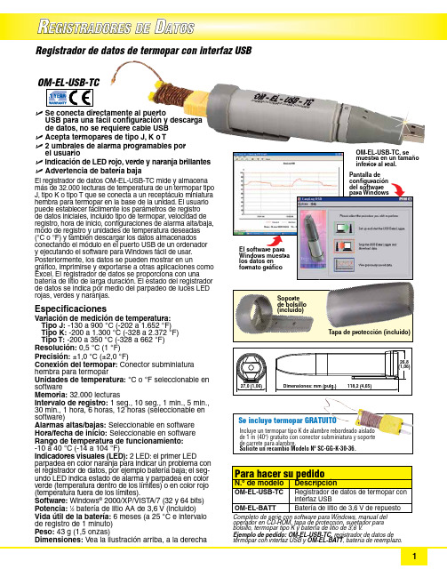
R EGISTRADORES DED ATOSU S e conecta directamente al puerto USB para una fácil configuración y descarga de datos, no se requiere cable USB U A cepta termopares de tipo J, K o T U 2 umbrales de alarma programables por el usuarioU I ndicación de LED rojo, verde y naranja brillantes U A dvertencia de batería bajaEl registrador de datos OM-EL-USB-TC mide y almacena más de 32.000 lecturas de temperatura de un termopar tipo J, tipo K o tipo T que se conecta a un receptáculo miniatura hembra para termopar en la base de la unidad. El usuario puede establecer fácilmente los parámetros de registro de datos iniciales, incluido tipo de termopar, velocidad de registro, hora de inicio, configuraciones de alarma alta/baja, modo de registro y unidades de temperatura deseadas(°C o °F) y también descargar los datos almacenados conectando el módulo en el puerto USB de un ordenador y ejecutando el software para Windows fácil de usar.Posteriormente, los datos se pueden mostrar en un gráfico, imprimirse y exportarse a otras aplicaciones como Excel. El registrador de datos se proporciona con una batería de litio de larga duración. El estado del registrador de datos se indica por medio del parpadeo de luces LED rojas, verdes y naranjas. Especificaciones Variación de medición de temperatura:T ipo J: -130 a 900 °C (-202 a 1.652 °F) Tipo K: -200 a 1.300 °C (-328 a 2.372 °F) Tipo T: -200 a 350 °C (-328 a 662 °F)Resolución: 0,5 °C (1 °F)Precisión: ±1,0 °C (±2,0 °F)Conexión del termopar: Conector subminiatura h embra para termopar Unidades de temperatura: °C o °F seleccionable en software Memoria: 32.000 lecturas Intervalo de registro: 1 seg., 10 seg., 1 min., 5 min., 30 min., 1 hora, 6 horas, 12 horas (seleccionable en software)Alarmas altas/bajas: Seleccionable en software Hora/fecha de inicio: Seleccionable en software Rango de temperatura de funcionamiento: -10 a 40 °C (-14 a 104 °F)Indicadores visuales (LED): 2 LED: el primer LED parpadea en color naranja para indicar un problema con el registrador de datos, por ejemplo batería baja; el seg-undo LED indica estado de alarma y parpadea en color verde (temperatura dentro de los límites) o en color rojo (temperatura fuera de los límites).Software: Windows ® 2000/XP/VIST A/7 (32 y 64 bits)Potencia: 1⁄2 batería de litio AA de 3,6 V (incluido)Vida útil de la batería: 6 meses (a 25 °C e intervalo de registro de 1 minuto)Peso: 43 g (1,5 onzas)Dimensiones: Vea la ilustración arriba, a la derecha Registrador de datos de termopar con interfaz USB configuración del software para Windows Soporte de bolsillo (incluido)Tapa de protección (incluido)operador en CD-ROM, tapa de protección, sujetador para bolsillo, termopar tipo K y batería de litio de 3,6 V .Ejemplo de pedido: OM-EL-USB-TC, registrador de datos de termopar con interfaz USB y OM-EL-BATT , batería de reemplazo.Incluye un termopar tipo K de alambre rebordeado aislado de 1 m (40") gratuito con conector subminiatura y soporte de carrete para alambre. Solicite un recambio Modelo Nº SC-GG-K-30-36.Se incluye termopar GRATUITO。
u-center简单使用手册

u-center使用手册
1、u-center每次打开都比较慢,要有点耐心
2、打开后,可以看到如图1的界面
图1
3、左边有如图2的图标
图2
第一个图标是选择串口,第二个是选择波特率,第三个是自动传输按钮
先选择串口(图标变绿,表示串口了解成功),然后选择波特率,最后点自动传输,如果GPS 有数据传输进来,界面就有变化了(如图3)。
这些功能也可以在菜单栏“receiver”中找到。
图3
4、收星情况说明如表1
表1
绿色是卫星可用于导航,
青色是卫星信号有效,可用于导航,
蓝色是信号有效,不可用于导航
红色是卫星信号无效
5、菜单栏中“view” “test console”,用于显示GPS收到的详细信息,如图4
图4
Test console界面按钮功能,如表2
表2
锁:用于锁定界面
叉叉:清除界面
过滤开关:可输入“RMC”,只显示GPRMC信息,如图5
图5
6、菜单栏中“view” “table view”,用于显示GPS收到的各个单独信息,如图6所示
图6
通过窗口下面的选项,再点击“+”就可以单独显示编号、时间、经纬度等等
7、菜单栏中“view”→“chart view”,用于显示GPS收到信息的图表形式,如图7所示
图7
点击上面那个图标,下面的图标就会变成可选的,然后自己选择需要的坐标参数8、菜单栏中“view”→“historgram view”,用于显示GPS收到信息的直方图形式,如图8所示
图8
概率直方图
Welcome To Download !!!
欢迎您的下载,资料仅供参考!。
德克德车载存储系统安装指南说明书

Watch short installation videos at /video | Register your system at /warrantyInstallation Instructions:MT5 / MT7TOOLS REQUIREDTOYOTA TACOMA5'1” BED LENGTHMT5 2005-2018 / MT7 2019-CURRENTVERSION 1.1 | 208.806.0251• Adjustable wrench (that opens to about 1”)• 1/2” open end wrench • #2 Phillips screwdriver, • Short 7/32” hex wrench • 7/16” deep socket • 3/8” socket• Electric drill • 9/64" drill bit • 1/4” drill bit • 5/16" drill bit • Drill stop • T40 Torx DriverCONTENTSDECKED carton LEFT deck half - 1RIGHT deck half - 1Center vert - 1Cabside vert - 1Drawer - 2Left ammo can - 1Right ammo can - 1Left stud - 1Right stud - 1Ammo can lid - 2C-channel - 2Ruler - 1Hardware box - 1Bottle opener - 1Torsion brace - 1Hardware box - unbagged components(inside DECKED carton):Shims - 4Weather strips - 2HARDWARE box - bagged componentsPREP-MT5 or MT7 - 1S1 - 1S2 - 1N1 - 1J4 - 2DRAWER 1 - 1DRAWER 2 - 1WHEELS - 1FINAL MID - 1PREP-EXTRA - 1MS WASHERS - 1(MT7 ONLY) TACOMA TD - 1▼ HEY! TORQUE BOY: READ BEFORE YOU INSTALL DECKED ▼1. DON’T be an idiot read the instructions.2. DON'T over tighten bolts, get em' hand-tight.3. DON'T use power tools.4.I f you don't follow directions and do use power tools:1). Set clutch at a very low setting. 2). If you blow it, see NOTE.*NOTE* T wo extra threaded inserts are included in BAG PREP-EXTRA . That’s all you get. The inserts will replace anystripped inserts in the tailgate ammo cans, but NOT THE CENTER VERT, so hand tighten until snug only! You can also screw the inserts back in if dislocated. There is a straight screwdriver slot on the underside of the insert.5. Start all bolts with fingers to avoid cross-threading6. DON'T over tighten J-hooks during installation. Make 'em good and snug enough to keep the system from moving in the bed.7. Nice job if you’re still reading .Prevent abusive, expletitive-filled language, watch our detailed installation videoor give us a call. We’re happy to help!208.806.0251 | /INSTALLVIDEOPREP BED: SHIMSNOTE: You will need to grab a pal for this step (or have incredibly long and flexible arms).• Remove top rear factory compartment bolt from the passenger side with a T40 Torx Driver. Keep bolt.• L oosely attach passanger side tailgate bracket with factory bolt in top hole. Make sure the tie down opening is angled toward the driver, not the tailgate ; BAG PREP-MT5 or MT7.• Align bracket so it's parallel with vertical edge of compartment. Tighten factory bolt at last!• Using the bottom hole in bracket as a guide, drill a 5/16" hole with a 1/2" drill stop through compartment and bed wall.• I nstall a 1" bolt through the bracket and bed wall. Install 1" washer and flanged nut and tighten securely ; BAG PREP-MT5 or MT7.• R epeat driver side unless you don't have a driver's side cubby. If not, follow the instructions for driver's side on next page. NOTE: On passenger side ONLY, you will need to add a washer; BAG PREP-MT5 or MT7... We know it's strange, trust us.(FOR TACOMAS WITH NO DRIVER SIDE TAILGATE CUBBY)NOTE: Disregard this page if you HAVE a driver's side tailgate cubby.• R eferencing dimensional info in DETAIL A mark hole locations and drill (2) 5/16" holes (with drill stop set at .62").• R eferencing DETAIL A install J-hook mounting bracket as shown with bolts, backing plate and nuts. Tighten bolts securely. BAG PREP-MT7, BAG TACOMA TD.DETAIL A DRIVER'S SIDE ONLYHOLE DRILLINGBOLT INSTALLATIONDRILL STOP.62"7.5" TO BOTTOM OF BED 5.75" FROM REAR OF BEDBOLTPLATEDETAIL AASSEMBLY: CENTER VERT + CABSIDE VERT NOTE: Perform the next few steps on a flat surface like a garage floor.• Attach center vert to cabside vert with four bolts. Alternate to tighten;BAG S1.ASSEMBLY: LOOSELY ATTACH STUDS (YUP)•LOOSELY attach studs to cabside vert with six bolts; BAG S1.ASSEMBLY: ALIGN & TIGHTEN STUDS (YUP) NOTE: This step ensures the studs are properly located before tightening bolts. It's important.• Place ammo cans to support tailgate end of deck panels.• Lift deck panels on center vert + stud + cabside vert assembly.• Slide studs around L-R until deck panels are seated.• DETAIL A: Loosely secure four bolts to hold decks onto studs; BAG S1.• Now you can securely tighten the bolts that hold the studs to the cabside vert.• Unbolt deck from studs, remove deck panels, save bolts, remove ammo cans and set aside for later assembly.STUD BRACKETTOP HOLECABSIDE BRACKET (GREY)STEP 1STEP 2NOTE: Make sure centerline arrows on cabside vert are aligned with your centerline mark (blue).STEP 3KEEP LOOSETIGHTENTHREE3 1/2"BOLTS3/4" BOLTCAB➡➡CABASSEMBLY: BRACKETS + MOUNTING• STEP 1: Securely attach stud bracket to driver side stud using three 3 1/2" bolts and three flanged nuts; BAG PREP-MT5 or MT7.• STEP 2: Loosely attach cabside bracket to the top hole in stud bracket with 3/4" bolt and flanged nut; BAG PREP-MT5 or MT7. KEEP LOOSE.• Repeat STEP 1 and STEP 2 on passenger side.• STEP 3: While supporting both ends, lift center vert + stud + cabside vert assembly in truck bed.FLANGED NUT➡CABFLANGED NUTSRECOMMENDED TORQUE: For all fasteners - 27 in-lb.INSTALL: CABSIDE BRACKET DRILL • Place driver side cabside bracket flush against truck bed wall, now tighten securely to stud bracket.• While keeping assembly on centerline, drill three 1/4" diameter holes into bed using cabside bracket as a guide (green holes). Make sure to use a drill stop set to 1/2" depth.1/4” DRILL BITDRILL STOP1/2”RECOMMENDED TORQUE:53 in-lb.INSTALL: BACKING PLATENOTE: If your pal left, clank some cans together to get them to come back.• Install three 1" bolts through holes in cabside bracket and pickup bed; BAG PREP-MT5 or MT7.• Play Rock Paper Scissors with your pal. The loser needs to hold the backing plate inside the wheel well and attach three flanged nuts; BAG PREP-MT5 or MT7. Securely tighten.• Repeat passenger side.INSTALL: C-CHANNEL• Loosely place driver side ammo can at tailgate corner of bed. The axles should be on the tailgate side of the truck.•INSTALL: DECK HALVES• Loosely place driver side deck panel on driver side stud, center vert and ammo can.• Shift tailgate ammo can forward, rearward, L-R, as necessary to align with fully seated deck panel.• Loosely assemble:• Five bolts (without washers) through deck panel into center vert; BAG S1.• Four bolts with nylon and rubber washers installed in order shown in DETAIL A through deck panel intostud; BAG S1,BAG MS WASHERS.• Eight bolts with nylon and rubber washers installed in order shown in DETAIL A through deck panel into tailgate ammo can; BAG S1,BAG MS WASHERS.• Tighten all S1 bolts.•Securely tighten driver side C-Channel/ammo can nut and bolt.• Repeat passenger side (make sure you don't forget to securely tighten passenger side C-Channel/ammo canINSTALL: J-HOOKS•Loosely assemble driver side J-hook assembly in order shown through tailgate side hole in ammo can; BAG J4.• Repeat passenger side.DRIVER SIDE AMMO CAN PASSENGER SIDE AMMO CANKEEP LOOSEKEEP LOOSEDRAWERS: BRACKETS + WHEELS • E ach drawer has a left and a right bracket. Bolt brackets into place via bottom two holes in bracket with 3/4"length bolts. Use the 2" length bolt for the upper cabside wall hole in bracket; BAG DRAWER 1.• Install a tube brace in each drawer with two 3/4" length bolts; BAG DRAWER 1, BAG DRAWER 2.DRAWERS: AXLE WHEELS + WEATHERSTRIPS • Slide narrow drawer into driver side drawer cavity. NOTE: It is easier to fully install narrow drawer first.➡FINAL STEPS: TORSION BRACE + BOTTLEOPENER• S lide torsion brace under center vert and tailgate ammo cans.NOTE: If you jumped the gun and tightened the J-hooks when installing, loosen them.• L oosely install:• T wo bolts with nylon washers through the end holes in torsion brace into ammo cans; BAG S1.• T wo bolts with nylon washers through the bottom bottle opener holes and torsion brace into center vert; BAG S1.• Two 1/2" length bolts through upper holes in bottle opener into center vert; BAG FINAL MID.• Align bottle opener to edges of center vert and tighten four bottle opener bolts.• T ighten end bolts into tailgate ammo cans.• F inally.....Tighten the J-hooks! DO NOT OVER TIGHTEN, just make snug. Make sure the gap between the sidewall of the bed and the deck is equal on both sides.9/64” DRILLBITDRILL STOP1/2”FINAL STEPS: AMMO CAN LIDS•DETAIL A: Ammo can lids are driver (marked L) and passenger (marked R) side specific.•DETAIL B: Holding lid in orientation shown, insert tab on tailgate end of ammo can lid and push the cabside end of lid down to secure. Don't be afraid to give'r the Fonzi to close, it's rugged.• Insert lock hole plugs, unless you ordered drawer locks! Install drawer locks now (instructions with locks); BAG FINAL MID.IMPORTANT: Grab your favorite beverage, crack 'er open in the bottle opener and christen this ship! You did it. Immediately post a photo of your significant other, child or canine (in no order of significance) a ppreciating your accomplishment. Add hashtag #DECKEDUSA | @DECKEDUSA .DETAIL A DRIVER SIDE AMMO CAN LID PASSENGER SIDE AMMO CAN LIDDECKED 3-YEAR LIMITED WARRANTY(a.k.a. LEGAL MUMBO JUMBO)DECKED LLC warrants to the original purchaser of this product that the product will be free from manufacturing defects in workmanship and materials for a period of three (3) years from the date of the original purchase. If within three (3) years from the original date of purchase this product fails due to defect in materials or workmanship, DECKED LLC will replace any defective part at its option.The original purchaser must contact the DECKED LLC customer service team and provide a description of the defective part, including digital pictures if requested, with the original purchase documentation as validation of warranty coverage or have previously activated their warranty online.This warranty DOES NOT cover or apply to:• Damage to the product due to misuse, mishandling and abuse.• Products not used in accordance with the manufacturer’s instructions or recommendations.• Product not assembled or installed according to manufacturer’s instructions.• Normal wear and tear.•U ndeclared damage to the system during shipping, acts of God. In addition, consequential damage and incidentaldamages (including lost time) such as damage to persons or property are not covered under this warranty.REGISTER YOUR PRODUCT FOR ANY FUTURE WARRANTY NEEDS. /REGISTER#DECKEDUSA | @DECKEDUSA | #DECKEDUSA | @DECKEDUSA MT5 / MT7 | v.1.1 | Page 21。
- 1、下载文档前请自行甄别文档内容的完整性,平台不提供额外的编辑、内容补充、找答案等附加服务。
- 2、"仅部分预览"的文档,不可在线预览部分如存在完整性等问题,可反馈申请退款(可完整预览的文档不适用该条件!)。
- 3、如文档侵犯您的权益,请联系客服反馈,我们会尽快为您处理(人工客服工作时间:9:00-18:30)。
U_DRC (镰刀臂)调试说明书
Ver 3.0
注1:本说明书中按钮用1号键-12号键代替,以逆时针方向从1号 到12号排列。
2、电位器的安装要点: ①必须在行程中间位置安装
②安装固定时,电位器主动与被动齿轮要平行,咬合松紧要恰当 ③电位器与外壳不能有碰压
3、设备进入工厂调试状态后,除了极限开关外,没有其它保护条件,操作时要小心,严格按照调试步骤进行参数设定,以免发生意外。
12 11 10 9
1 2 3 4
一、进入工厂调试状态:
先按8号键再按电源启动键,启动设备,当显示屏上显示 “ EASTERN ”放开8号键,当显示屏上显示debugging program 时,表明设备已进入工厂调试状态。
二、进入FID (垂直方向)参数设置:
FID 共需输入3个参数: 按8号键,显示屏上显示:
debugging program FID
1st:(低位) 2nd:(旋转安全位) 3rd:(高位)
1
、 按FID 下降键,U 臂下降到最低位置后自动停止,然后按FID
上升键,使U 臂脱离下端极限位1-2cm ,按5号键,显示屏在1st:后显示OK !
屏幕显示: debugging program FID
1st: OK (实际值47CM 2nd: 3rd:
640
2、按FID 上升键,U 臂上升到最高位置后自动停止,然后按FID 下
降键,使U 臂脱离上端极限位1-2cm ,按7号键,显示屏在3rd:后显示OK !
屏幕显示: Debugging program FID 1st: 2nd:
3rd: OK (实际值
3、按FID 上升键或下降键,使U 臂中心离地1400MM ,(用尺量)按6号键,显示屏在2nd: OK ,(客户可根据实际来设置,将床推入,通过FID+.-,来设置高度,后只需点击6号键重新保存即可)
屏幕显示: debugging program FID
1st: 2nd: OK 3rd:
按8号键退出FID 调试状态,进入SID 界面。
三、SID (水平方向)调试:
屏幕显示: debugging program SID 1st: 2nd: 3rd:
1、按SID 回退键或伸出键,使球管回到U 臂行程中间点,后调整电位器齿轮,使右下角显示数字2048
,按6号键,显示屏在2nd:后显示OK !
屏幕显示: debugging program SID
1st: 2nd: OK 3rd: 2、按SID 回退键,球管回退到最近端位置(内)后自动停止,然后按SID 伸出键,使球管脱离最近端极限位1-2cm ,按5号键,显示屏在1st:后显示OK !
屏幕显示: debugging program 1st: OK 2nd: 3rd:
2、按SID 伸出键,球管伸出到最远端位置(外)后自动停止,然后按SID 回退键,使球管脱离最远端极限位1-2cm ,按7号键,显示屏在3rd:后显示OK !
屏幕显示: debugging program
1st: 2nd: 3rd: OK 4、按
8号键退出SID 调试状态。
进入Angle 界面 四、Angle
(旋转)调试:
屏幕显示:: debugging program 1st: 2nd:
1、按角度逆转键,或按角度顺转键,当U 臂与地面平行时停止,按
6号键,显示屏在2nd:后显示OK ! 屏幕显示:: debugging program 1st: 2nd: OK 3rd:
2、按角度逆转键,U臂逆时针转动,当U臂与地面垂直时停止,然后按5号键,显示屏在1st:后显示OK!
屏幕显示::debugging program
1st: OK
2nd:
注:3rd 此项不设
3、按8号键退出Angle调试状态。
五、按电源关闭键,退出工厂调试状态。
六、按电源启动键,重新启动设备,进入正常使用状态。
屏幕显示::
FID: XXXX mm
SID: XXXX mm
Angle: +/- XX
七、旋转按键操作时会自动上升或者下降到旋转安全位置之后旋转。
八、按一键功能(需按住2秒以上时间)过程中再按一次正在运行的
自动键来退出。
九、如需自动运行老练模式,先按任一功能键后,再按一下8号键,
同时8号指示灯点亮,如退出,再按一下8号键,指示灯灭退出。
十、保护功能,如FID电位器有损坏,在按下一键功能时,1.5秒后,
自动保护,退出一键定位。
请注意!!!。