MAX1136KEUA中文资料
MAX1239MEEE+T中文资料

元器件交易网
2.7V to 3.6V and 4.5V to 5.5V, Low-Power, 4-/12-Channel, 2-Wire Serial, 12-Bit ADCs MAX1236–MAX1239
ABSOLUTE MAXIMUM RATINGS
VDD to GND ..............................................................-0.3V to +6V AIN0–AIN11, REF to GND ............-0.3V to the lower of (VDD + 0.3V) and 6V SDA, SCL to GND.....................................................-0.3V to +6V Maximum Current Into Any Pin .........................................±50mA Continuous Power Dissipation (TA = +70°C) 8-Pin µMAX (derate 4.5mW/°C above +70°C) .............362mW 16-Pin QSOP (derate 8.3mW/°C above +70°C)........666.7mW Operating Temperature Range ...........................-40°C to +85°C Juห้องสมุดไป่ตู้ction Temperature ......................................................+150°C Storage Temperature Range .............................-60°C to +150°C Lead Temperature (soldering, 10s) .................................+300°C
MAX941CSA中文资料

ELECTRICAL CHARACTERISTICS
(V+ = 2.7V to 6.0V, TA = TMIN to TMAX, unless otherwise noted. Typical values are at TA = +25°C. See Note 14.)
PARAMETER Positive Supply Voltage Input Voltage Range
Internal hysteresis ensures clean output switching, even with slow-moving input signals. The MAX941 features latch enable and device shutdown.
The single MAX941 and dual MAX942 are offered in a tiny µMAX package. Both the single and dual MAX942 are available in 8-pin DIP and SO packages. The quad MAX944 comes in 14-pin DIP and narrow SO packages.
__________________________________________________________Pin Configurations
TOP VIEW
MAX941
V+ 1 IN+ 2 IN- 3 SHDN 4
8 N.C. 7 OUT 6 GND 5 LATCH
DIP/SO/µMAX
SYMBOL V+
V
MIN TYP MAX UNITS
友声收银系列电子秤使用说明书
是整机保修一年收银系列使用说明书适用型号TM-30A /TM-15A / TM-6AJB-30A / JB-15A / JB-6A2009年7月Version2.30A上海友声衡器有限公司 & 上海精函衡器有限公司沪制00000033号沪制00000319号地址:上海市闵行区莘庄工业区春光路99弄58号邮编:201108厂址:上海市崇明县庙镇经济开发区宏海公路349号邮编:202165 公司总机:(021)54831805/6/7/8 技术部总机:(021)54831858传真:(021)54831803 主页:指定代理与售后服务电话:联系人:感谢您使用上海精函有限公司的产品!在您开始使用本产品前,请务必仔细阅读《前言》中的内容,并严格遵守这些事项!1.1注意事项➢确保电源插头和电源线连接正常,使用三芯电源线进行连接,如果使用了拖线板,则拖线板的插口也要是三芯的,确保三芯的地线妥善的与建筑大地连接,以避免漏电的情况。
➢切勿用沾湿的手插拔电源插头,这样可能导致触电。
➢严禁将身体重力压在秤盘上,以免损坏称重传感器。
➢严禁撞击重压,或用重物冲击秤盘,以免损坏称重传感器,同时勿超过其最大称量范围。
➢严禁淋雨或用水冲洗;如不慎沾水,请用干布擦试干净;若秤体工作异常,请尽速送到经销商处,我们将竭诚为您服务。
➢严禁将条码秤置于极低温、高温或潮湿的场所,这样可能导致秤体工作异常甚至损坏。
➢严禁用有机化学溶剂擦拭外壳和面板。
➢严禁私自打开秤体,也不要让非专业的维修人员修理本秤。
➢严禁将手从打印机旋出位置伸入,该行为可能造成220V触电。
➢在有本公司专业维修人员指导下打开秤体时,请务必提前拔出220V的交流供电。
➢不要试图拆卸秤体内的开关电源,高压电容需要非常长时间才能完全放电,未放电的情况下拆卸可能导致触电。
➢建议使用本厂出售的热敏纸,本秤体对本厂出售的热敏纸进行过长时间的测试与优化,可以较好的保证头片的使用寿命。
MAXIEZ调试资料(印板名称及设定)

MAXIEZ调试资料(印板名称及设定)MAXIEZ-CZ 印板型号及设定PCBP1 R1 R2 M1 E1 PS1 Z1(功能)KCD-1161XKCA-941X CA-1005X CR-905X KCR-943XKCR-950XKCA-1191XKCD-1162X KCR-946X KCA-1192X 注:KCD-1161 可以替代 KCD-1151逆变单元转换器逆变模块电容板二极管IPM 150A KCN-943A IGBT 200A KCN-920A印板型号发光管功能状态电容板DCV 当主回路电解电容正常充放电时点亮。
M1板PWD 当应急电池供电时点亮41DG 当层、轿门联锁开关接通时点亮。
DZ 当轿厢运行到平层区域内时点亮。
60 当电梯运行于自动方式时点亮。
【注意】即使电源已经被切断并且发光二极管 DCV 熄灭的状态,也不要立即接触逆变单元组件。
如果要接触,必须先使用电压表测量整流二极管模块输出的直流电压,确认回路已可靠关闭。
【注意】只有在重写程序时,才把 R/M/MNT/FWR 拨到 FWR 位置。
修改参数时,拨到R/M 或者 MNT 。
关闭电源或者重启 CPU 时,请处于 R/M 或者 MNT 位置(a)调试功能,显示信号功能,调试数据显示功能设定 SET1/0 开关方法如下:1. 设定 SET0 数值。
2. 按下 SW1▽(确认 0.25 秒以上) 。
3. 设定 SET0 后(设定模式后),基本显示会显示几秒钟。
4. 基本信息之后会显示出所需的显示。
(b)PTSH,DNSH,WGHG,WGHO 和FSHFT 开关设定功能。
通过按下 SW1▽两次,确认调试数据的更新(重新写入闪存) 重复两次地确认来重新输入调试数据通过操作 SW1▽设定 SET1/0 开关方法如下:1. 设定 SET1/0 的数值。
2. 按下 SW1▽(确认 0.25 秒以上) 原先的数值会在按下 SW1▽后显示。
迈信电气EP3使用说明

马拉松MX系列发电机英文说明书

MAGNAMAXGENERATOR INSTALLATION OPERATION, AND MAINTENANCEMANUALTABLE OF CONTENTSTABLE OF CONTENTS (2)SAFETY (6)GENERAL INFORMATION (7)MECHANICAL DESIGN (7)General (7)Conduit Box (7)MagnaMAX Unirotor TM Construction (7)Adapters and Drive Discs (7)ELECTRICAL DESIGN (8)Temperature Rise (8)Standby Generator Ratings (8)Premium Insulation System (8)Power Factor (8)MagnaMAX Voltage Regulator (8)HOW TO READ A MODEL NUMBER (9)INSTALLATION (10)RECEIVING YOUR MAGNAMAX GENERATOR (10)UNPACKING AND HANDLING (10)STORAGE (10)PREPARATION FOR USE (10)GENERATOR MOUNTING - SINGLE BEARING (10)GENERATOR MOUNTING-TWO BEARING (11)BELT DRIVE (11)ENVIRONMENTAL CONCERNS (11)ELECTRICAL CONNECTIONS (12)GENERATOR LEAD CONNECTIONS (12)12 LEAD HIGH WYE CONNECTION (13)12 LEAD LOW WYE CONNECTION (13)12 LEAD HIGH DELTA CONNECTION (14)12 LEAD LOW DELTA CONNECTION (14)10 LEAD HIGH WYE CONNECTION (15)10 LEAD LOW WYE CONNECTION (15)6 LEAD WYE CONNECTION (16)6 LEAD DELTA CONNECTION (16)3 LEAD DELTA CONNECTION (17)4 LEAD WYE CONNECTION (17)DOUBLE DELTA -- SINGLE PHASE CONNECTION (18)LOW ZIG ZAG -- SINGLE PHASE CONNECTION (18)HIGH ZIG ZAG -- SINGLE PHASE CONNECTION (18)PARALLELING OPERATIONS (19)PRIME MOVER (19)VOLTAGE REGULATOR (19)SWITCHGEAR (19)PARALLELING BASICS (19)REACTIVE LOAD CONTROL (20)PARALLELING CIRCUITRY (20)THYRISTOR OR SCR LOADING (21)OPERATION (21)PRE-START INSPECTION (21)STARTING-UP THE GENERATOR (22)FIELD FLASHING (22)VOLTAGE ADJUSTMENTS (22)OTHER ADJUSTMENTS (23)MAINTENANCE (23)GENERAL INFORMATION (23)AIR INTAKE AND EXHAUST (23)ELECTRICAL CONNECTIONS, WINDINGS (24)LUBRICATION (24)DRYING ELECTRICAL INSULATION (26)Space Heaters (26)Oven (26)Forced Air (26)“Short Circuit” Method (26)CLEANING METHODS (27)Solvents (27)Cloth and Compressed Air (27)Brushing and Vacuum Cleaning (27)Shell Blasting (27)Steam Cleaning (27)DISASSEMBLY (28)REMOVAL FROM PRIME MOVER (28)CONDUIT BOX REMOVAL (29)EXCITER STATOR (FIELD) REMOVAL (30)EXCITER ARMATURE (ROTOR) REMOVAL (30)PMG STATOR REMOVAL (31)MAIN ROTOR REMOVAL (33)FRONT END BRACKET REMOVAL (35)EXCITER INSPECTION (35)EXCITER STATOR (35)EXCITER (ROTOR) ARMATURE (36)PMG INSPECTION (37)PMG STATOR (37)PMG ROTOR (37)MAIN ROTOR INSPECTION (37)BEARING (37)FAN (38)MAIN ROTOR CORE AND WINDINGS (40)DRIVE DISCS (SINGLE BEARING GENERATORS ONLY) (40)FRONT (EXCITER) END BRACKET INSPECTION (40)DRIVE END BRACKET OR SAE ADAPTER INSPECTION (41)MAIN STATOR INSPECTION (42)FRONT END BRACKET INSTALLATION (42)MAIN ROTOR INSTALLATION (42)PMG INSTALLATION (45)EXCITER INSTALLATION (46)CONDUIT BOX INSTALLATION (47)ASSEMBLY TO PRIME MOVER (48)TROUBLESHOOTING (50)INTRODUCTION (50)SYMPTOM: (51)NO VOLTAGE OR RESIDUAL VOLTAGE (51)LOW VOLTAGE - (52)NO LOAD (52)LOW VOLTAGE WHEN LOAD IS APPLIED (53)HIGH VOLTAGE (53)VOLTAGE IS FLUCTUATING (54)OPERATES SATISFACTORILY WHEN COLD, BUT SHUTS DOWN WHEN WARM (54)BUILDS VOLTAGE FROM STARTUP,THEN GOES TO LOW (RESIDUAL) VOLTAGE (54)EQUIPMENT RUNS NORMALLY ON UTILITY POWER, BUT WILL NOT RUN ON GENERATOR SET (54)GENERATOR TESTING (55)VISUAL INSPECTION (55)CONSTANT EXCITATION (12V BATTERY) TEST (55)MEASURING VOLTAGES (56)TYPICAL VOLTAGE MEASUREMENTS (57)Generator Output Voltage (57)Regulator Output (Exciter Stator Input) (57)Regulator Sensing (57)Regulator Input Volts (PMG Output Volts) (57)CURRENT (AMP) MEASUREMENTS (57)MEASURING RESISTANCE (58)Main Stator (58)Exciter Rotor (58)TESTING DIODES (RECTIFIERS) (58)INSULATION RESISTANCE - MAIN STATOR (59)GENERATOR TESTING (59)INSULATION RESISTANCE - MAIN ROTOR (59)INSULATION RESISTANCE - EXCITER STATOR (60)INSULATION RESISTANCE - EXCITER ROTOR (60)MAIN ROTOR FIELD AC IMPEDANCE TEST (60)MAGNAMAX EXPLODED VIEW (61)STANDARD TOOLS (64)SPECIAL TOOLS (65)MISCELLANEOUS (66)PREPARATION FOR SHIPMENT OR EXTENDED STORAGE (66)SHIPPING INSTRUCTIONS (66)STORAGE INSTRUCTIONS (66)TABLE 12-1: MAGNA MAX - FASTENER AND TORQUE SPECIFICATIONS (68)TABLE 12-2: CAPSCREW TORQUE VALUES (69)TABLE 12-3:EXCITATION DATA -60 HZ - 1800 RPM (70)TABLE 12-3:EXCITATION DATA -50 HZ - 1500 RPM (71)TABLE 12-5: RESISTANCE VALUES - MAIN WINDINGS (72)TABLE 12-6: RESISTANCE VALUES - EXCITER WINDINGS (73)SAFETYPLEASE REMEMBER SAFETY FIRST. If you are not sure of the instructions or procedures, seek qualified help before continuing.This service manual emphasizes the safety precautions necessary during the installation, opera-tion, and maintenance of your generator.Each section has caution and warning messages. These messages are for your safety and the safety of the equipment involved. If any of the cautions or warnings is not readily understood, seek clarification from qualified personnel before proceeding.Before any service work is done, disconnect all power sources and, where appropriate, lock out all controls, to prevent an unexpected start-up of the generator set. Proper grounding in compliance with local and national electrical codes must be provided. These safety precautions are necessary to prevent potential serious personal injury, or even death.The hazards associated with lifting or moving the generator are pointed out in the installation and service sections; incorrect lifting or moving can result in personal injury or property damage.Whenever the generator is running, always assume and proceed as if voltage is present. Residual voltage is present at the generator leads and at the regulator panel connections, even with the regulator fuse removed. Caution must be observed, or serious personal injury or death can result.Whenever solvents, cleaners, or flammable liquids are present, adequate ventilation must be available to avoid fire, explosion, and health hazards. Always avoid breathing vapors and use suitable personal protective equipment to prevent personal injuries. (Such as eyes, face, and hand protection.)This manual is not intended to be a substitute for properly trained personnel. Only qualified trained people should attempt repairs. The cautions and warnings point out known conditions that are potentially dangerous. Each installation will create its own set of circumstances. No manual can cover every possible situation.When in doubt, ask. Don’t be embarrassed to ask, “dumb questions”. Remember that dumb questions are much easier to handle than dumb mistakes.GENERAL INFORMATION MECHANICAL DESIGNGeneralAll single and two bearing units are manufactured with cast iron end brackets and adapters, and fabricated steel frames. Flexible drive discs and SAE adapters are machined to SAE standards. Pre-lubricated, regreasable, shielded ball bearings are used on MagnaMAX generators. Standard units are fully guarded. Drip proof shields are available as an option.Conduit BoxThe large end mounted conduit box is con-structed of formed sheet steel that will allow the addition of top mounted control packages. Refer to Marathon Electric for top mounted controls of more than 240 lbs. There is ample room inside the conduit box for a circuit breaker (through 800A Frame) and other options. The conduit box cover properly directs outside ventilating air through the generator.MagnaMAX Unirotor TM Construction An aluminum die cast rotor core affords high mechanical integrity and low vibration at operating speeds. Amortisseur winding and coil supports are die cast as an integral part of the rotor. Laminations are 4-pole, one piece laminations which are shrunk fit and keyed to the shaft. No dovetails, cross bolts or other pole to shaft connecting devices are used. The cast unidirectional aluminum alloy ventilation fan provides even air distribution to maximize cooling and generator efficiency.Adapters and Drive DiscsAll single bearing units are available with several adapters and drive disc arrangements. These can be shipped to order or can be changed in the field with standard shop tools. When changing flexible drive discs, spacers are used between the discs and the cast iron hub to maintain SAE standard dimensions.ELECTRICAL DESIGNAll standard products have 2/3 pitch main windings to eliminate the third harmonic. This serves to lower operating temperatures, give lower harmonic content and better waveform, and extend the overall life of the generator.Temperature RiseAll ratings and frame sizes are based on NEMA and CSA Class F and Class H temperature rises on both the rotor and stator windings. Ratings for British, German, French, IEC and all popular marine agencies are available.Standby Generator Ratings Synchronous generators used on emergency backup power can have temperature rises up to 25°C above those for continuous operation. (NEMA MG1 -22.40 and MG 1-22.84).Premium Insulation SystemAll MagnaMAX generators are built with Class H or better insulation materials. All standard generators are suitable for continuous duty at Class F temperature rise and will give equivalent or better winding life expectancy to generators supplied with Class A or B insulation systems operated within their temperature limits. The varnishes and epoxies used are synthetic, non-hygroscopic. Multiple dip and bake cycles of the main winding, plus a final coat of epoxy, make the standard winding moisture and fungus resistant. The MagnaMAX rotor is wet wound with thermo-setting epoxy applied between each layer, plus a final coating of epoxy for moisture and abrasion resistance. MagnaMAX generators can be ordered with an epoxy vacuum pressure impregnated insulation system as an option. (MagnaMAX generators with form wound coils include VPI as standard.)Power FactorAll standard generators are designed for operation at rated kVA at 0.8 lagging power factor but can be operated at rated kVA over the 0.8 to 1 .0 power factor range. MagnaMAX Voltage RegulatorThe standard voltage regulator is a fully encapsulated, static types with a solid state build up circuit. Standard features include 3-phase RMS sensing, paralleling, adjustable under frequency protection, and over excitation protection. The regulator meets EMI suppression to Mil Std-461B, part 9. An optional feature is adjustable armature current limiting. See the regulator manual for more information.HOW TO READ A MODEL NUMBERIt is extremely important to properly identify the machine when requesting parts or service. Always have the generator model number and serial number when requesting information from the factory. We cannot help you without this information.An Example For MagnaMAX Generators 431RSL 2000 AA - 000Character Category Description1st three characters Frame Number4th character Winding type R—Random WoundF—Form Wound5th character Bearing arrangement S—1 BearingD—2Bearings6th character Voltage range L—Up to 480 voltsM—1000-6600 voltsS—600 volts7th Character Product style4-Magna8th Character Type9th & 10th Character Wk2 Code11th Character Modification A-Z assigned sequentially 12th Character Mounting Arrangement A-Y see chart figurer 2-1 13th, 14th & 15th characters Modification numbers For internal use only Arrangement Adapter SAE Size Drive Disc SAE SizeA311-1/2B211-1/2C48D310E111-1/2F114G47-1/2H1DelcoJ1/214K210L1/2DelcoM014N2Small Delco0None NoneP018S0DelcoU0018V46-1/2W0021Y410Figure 2-1INSTALLATIONRECEIVING YOUR MAGNAMAX GENERATORUpon receipt of the generator, it is recommended that it be carefully examined for possible damage incurred in shipment. The generator was given to the Freight Company in good condition, and they are responsible for the product from our dock to yours. Any damage should be noted on the freight bill before accepting the shipment. Claims for damages must be promptly filed with the Freight Company. UNPACKING AND HANDLINGRead all instruction cards carefully. When lifting, attach an overhead crane to the lifting lugs on the generator frame. Apply lifting forces in a vertical direction.WARNINGTHE LIFTING LUGS ON THE GENERATOR ARE DESIGNED TO SUPPORT THE GENERATOR ONLY.DO NOT LIFT COMPLETE GENERATOR SET BY MEANS OF LIFTING DEVICES ON THE GENERATOR. PERSONAL INJURYOR QUIPMENT DAMAGE MAYOCCUR.STORAGEIn the event that the generator is not to be installed on the prime mover immediately, it is recommended that it be stored in a clean, dry area that is not subject to rapid changes in temperature and humidity. See "STORAGE INSTRUCTIONS" for more information.PREPARATION FOR USEAlthough the generator is carefully inspected and tested in operation before it leaves the factory, it is recommended the unit be thoroughly inspected. The insulation on the wire should be inspected and all bolts should be checked for tightness.Remove all shipping tapes, bags, blocks, and skids, which are used to prevent vibration and rotor movement during shipment. Dry, low-pressure compressed air of approximately 30 PSI (206 KPA) can be used to blow out the interior of the generator. In the case of two bearing machines, it is possible to turn the rotor by hand to make sure that it rotates smoothly without binding.If the machine has been in storage for a year or longer it is recommended that it be lubricated according to the lubrication instructions and chart supplied in the maintenance section.If the machine has been exposed to damp, humid conditions the insulation resistance should be checked. Refer to the instructions supplied in this manual.GENERATOR MOUNTING - SINGLE BEARINGSingle bearing generators are provided with an SAE flywheel adapter and flexible drive discs. Very close tolerances are maintained in the manufacture of the generator so that the alignment procedure is extremely simple. A coupling hub of nodular iron is shrunk on the shaft and special steel drivediscs are bolted to the hub. Holes are provided in the periphery of the coupling disc, which correspond to tapped holes inthe flywheel. The outside diameter of the discs fits in a rabbet in the flywheel so that concentricity is assured in all cases.WARNINGDO NOT APPLY ANY FORCE TO THE GENERATOR FAN FOR LIFITNG OR FOR ROTATING THE GENERATORROTOR. DISREGARDING THESEINSTRUCTIONS MAY CAUSE PERSONAL INJURY OR EQUIPMENTDAMAGECAUTION:GRADE 8 CAPSCREWSOR GRADE 8 PLACE-BOLTS AND HARDENED WASHERS ARE REC-OMMENDED TO MOUNT THE DRIVE DISCS TO THE FLYWHEEL.DO NOT USE HELICAL OR OTHER LOCKING DEVICES UNLESS APPROVED.The SAE adapter and the flywheel housing are designed to match each other with no further alignment necessary. Shims may be necessary under the feet of the generator to insure a solid mounting. See THE SERVICE SECTION for more information. GENERATOR MOUNTING-TWOBEARINGTwo bearing generators are provided with a shaft extension and key way. For direct-coupled sets the assembler furnishes a flexible coupling which is installed between the driver and the generator shaft.IMPORTANT: Aligning the two machinesas accurately as possible will reduce vibration, increase-bearing life, and insures minimum coupling wear. It may be necessary to shim the generator feet for proper support and alignment. Consult the coupling manufacturer’s instructions for alignment specifications and procedures. BELT DRIVEPlease refer to Marathon Electric for applications involving belt driven installations.ENVIRONMENTAL CONCERNSDirt, moisture, heat, and vibration are enemies of electrical equipment. The ambient temperature should not exceed the value shown on the generator nameplate. Generators for outdoor application should be protected from the elements by housings with proper openings for ventilation. This protection should be designed to prevent the direct contact of wind driven rain, snow, or dust with the generator. In moist or humid areas, such as the Tropics and marine serv-ice, additional protection is recommended. Although the standard windings are humidity and moisture resistant, special insulation and accessories such as space heaters can increase generator life. In extremely dirty and dusty environments a means of providing filtered cooling air to the generator is recommended. Please refer to Marathon Electric for filter kits that are available.ELECTRICAL CONNECTIONSThe generator conduit box construction allows conduit to enter the top, bottom, or either side of the box. A hole-saw or any suitable tool can be used to provide for the conduit entrance. Protect the interior of the generator from shavings when drilling or sawing. An approved connector must be used in conjunction with the conduit.To minimize the transmission of vibration, it is essential that flexible conduit be used for all electrical cable entrance to the generator. Refer to the connection diagram supplied with the generator and / or the proper diagrams shown in this section. Install all intercomponent and external wiring in accordance with the regulations of the national and local electrical codes. Clean all contact surfaces to assure good electrical bonding with the generator lugs or bus bars. Use heavy-duty terminal lugs or good quality clamps for making all connections. Insulate all connections in accordance with national and local regulations.Be sure the generator frame is grounded to all the other components of the system with a ground wire in accordance with national and local regulations.GENERATOR LEAD CONNECTIONS The electrical connections in the conduit box should be made in accordance with the appropriate “connection diagram.” Use the diagram appropriate for the number of leads and voltage range required. Refer to the drawings supplied with the generator and to drawings in this section.The final voltage setting is established within the selected range by an adjustment of the voltage regulator.CAUTION:SOME GENERATORS HAVE MULTIPLE, IDENTICALLY MARKED, CABLES FOR EACH LEAD. CONNECT ALL IDENTICALLY MARKED CABLES TOGETHER WHEN MAKING CONNECTIONS.PARALLELING OPERATIONSMagnaMAX generators come standard with amortisseur windings die cast as an integral part of the rotor. This exclusive, Unirotor TM, construction makes all MagnaMAX generators suitable for paralleling operations when the proper control equipment is added. Paralleling with other generator sets and / or with the utility power grid offers a number of advantages. Multiple unit installations increase power capacity; they can be added or removed from the line depending on the load requirements; they can be better maintained and repaired (since single source breakdown would mean total loss of power), and they often provide more reliable, efficient, and economical operation.Successful parallel operation means that the generators deliver power to the external system without delivering power to each other, or accepting power from the load bus or power grid. Additional equipment is necessary to insure safe and successful operation. PRIME MOVERThe prime mover provides the speed and torque which will be necessary to keep the machines in synchronized operation. A governor controls the prime mover's speed. The governor will directly control the watt or kW output and frequency of the unit. The governor must have special paralleling provisions to permit parallel operation with the other machines.VOLTAGE REGULATORThe voltage regulator controls the generator output voltage and the reactive power supplied by the generator. When two or more ac generators operate in parallel, the voltage regulator must have paralleling provisions (either internally or external to the regulator) to control the reactive or VAR load while it is in parallel operation. A separate paralleling current transformer is required to sense the reactive current and signal the voltage regulator. This additional paralleling circuitry is absolutely necessary to control the reactive current flowing between the generator sets. SWITCHGEARThere are additional relays and breaker controls that are necessary to insure safe, trouble free operation of paralleled units. Reverse power relays monitor the direction of power flow to insure that the generator is delivering power, not accepting it. These power relays control breakers, which are a means of connecting and disconnecting the gen-erator from the load. The total system can include over-voltage, over-current protection, under fre-quency protection, power factor correction provi-sion and a variety of associated control equipment from manual switchgear to microprocessors. The amount of control gear and level of sophistication will be determined by the needs and requirements of the particular application.PARALLELING BASICSThe following points are basic criteria which must be met before two units can be paralleled. THIS IS NOT MEANT TO BE SPECIFIC INSTRUCTIONS FOR PARALLELING OPERATION.1. Additional paralleling circuitryA. Voltage regulator-paralleling provisionsB.Paralleling current transformer(s)C. Paralleling provisions on governor controlsD. Switchgear2. The voltage and frequency must be the same for all sets with voltages in phase.3. The voltage regulation characteristics of the individual generators should be similar.4. The generators must have the same phase rotation.5.The driving engines should have the same speed regulation characteristics and the governors should be adjusted to give the same speed regulation.Before operating generator sets in parallel, each set should be checked by starting, operating, and adjusting the sets as individual units before attempting paralleling. REACTIVE LOAD CONTROLWhen two identical generators are operating together in parallel and an unbalance occurs in field excitation, circulating currents begin to flow between the generators. This current will appear as a lagging power factor or inductive load to the highly excited generator, and as a leading power factor or capacitive load to the generator with the lower field current. This is known as the reactive circulating current and there are two methods of controlling it in parallel operation:1. Reactive droop compensation. (Formerly known as parallel droop compensation.)The bus voltage droops, or decreases, as the reactive lagging power factor load is increased.2. Reactive differential compensation. (Formerly known as cross current compensation.) The reactive differential compensation circuit allows parallel generators to share reactive loads with no decrease or droop in generator voltage.The circuit must meet the following criteria:A.All paralleling current transformers for all the generators being paralleled must be included in the secondary interconnection loop.B. When different size generators are paralleled all paralleling current transformers must have the same proportional ratios that give approximately the same secondary current.C. Voltage regulator paralleling circuitry must be the same.D. Current transformer secondary and the generator lines must be isolated electrically.E. It is also desirable to have an auxiliary contact on the main generator breaker to short the parallel CT secondary when that breaker is open (not connected to the load bus).Because of the above criteria, reactive differential compensation cannot be used when paralleling with the utility power grid. There is no limit, however, in the number of generators that can be included in this type of circuit. PARALLELING CIRCUITRYBecause of the number of variables involved in paralleling generator sets, every installation will have its own circuitry and methods or procedure of bringing paralleled units on line. There are numerous ways of connecting paralleled units and an almost unlimited variety of applications and associated equipment.When parallel operation is desired, it is important that the control manufacturer, the generator manu-facturer, and the systems engineer work together to insure the proper selection of all components. Please refer to Marathon Electric for application assistance.THYRISTOR OR SCR LOADING Solid state electronic control devices which utilize thyristors or SCR firing circuits (such as variable frequency induction motor controls, precision motor speed controls, no-break powered battery chargers, etc.) can introduce high frequency harmonics which adversely affect or destroy the normal waveform of the generator. This creates additional heat in the generator stator and rotor, and can cause overheating. These devices can and do present problems to non-utility power generating equipment or any limited power bus system. The problems that can occur are not limited to the generator itself, but can effect the solid state control device, the equipment it controls, other associated loads, monitoring devices or a number of combinations over the entire system.MagnaMAX generators can supply power to thyristor or SCR loads when properly applied. The standard voltage regulator is PMG powered and senses 3 phase RMS voltages for maximum stability against severely distorted waveforms. SCR type applications such as cranes, shovels, etc., require special consideration of the generator insulation system due to greater dielectric stress and severe environmental conditions. It is impor-tant that the control manufacturer, the generator manufacturer, and the systems engineer work together to insure the proper selection of all components. Please refer to Marathon Electric for application assistance. OPERATIONPRE-START INSPECTIONBefore operating the generator for the first time, the following checks are recommended.1. A visual inspection should be made to check for any loose parts, connections, or foreign materials2. Check for clearance in the generator and exciter air gap. Be sure the generator set turns over freely. Bar the generator over by hand at least 2 revolutions to be sure there is no interference.WARNINGDO NOT APPLY ANY FORCE TO THEGENERATOR FAN FOR LIFITNG ORFOR ROTATING THE GENERATORROTOR. DISREGARDING THESEINSTRUCTIONS MAY CAUSE PERSONAL INJURY OR EQUIPMENTDAMAGE3. Check all wiring against the proper connection diagrams and make sure all connections are properly insulated. Support and tie leads to keep them from being damaged by rotating parts or by chafing on sharp corners.4. Be sure the equipment is properly grounded.5. Inspect for any remaining packing materials and remove any loose debris, building materials, rags, etc. that could be drawn into the generator.6. Check fasteners for tightness.7. Check to be sure no tools or other hardware have been left inside or near the machine.8. Install and check to be sure all covers and guards are in place and secure.WARNINGRESIDUAL VOLTAGE IS PRESENT AT THE GENERATOR LEADS AND AT THE REULATOR PANEL CONNECTIONS EVEN WITH THE REGULATOR FUSE REMOVED.CAUTION MUST BE OBSERVED OR SERIOUS PERSONAL INJURY OR DEATHCAN RESULT.STARTING-UP THE GENERATORThe following procedure should be followed for starting-up the generator for the first time:1.The generator output must be disconnected from the load. Be certain that the main circuit breaker is open.2.D isable the voltage regulator by removing the fuse.WARNINGDO NOT OVERSPEED THEGENERATOR. EXCESSIVE CENTRIFUGAL FORCES COULD DAMAGE THE ROTATING FIELDS. BE PREPARED FOR AN EMERGENCYSHUTDOWN.3.F ollow the manufacturer's instructions and start the prime mover. Check the speed and adjust to the RPM shown on the generator nameplate.4.Replace the regulator fuse and adjust the voltage to the required. Check all line to line and line to neutral voltages to be sure they are correct and balanced. If the voltages are not correct shut down immediately and recheck all connections.5. Close the main circuit breaker and apply the load.6. Monitor the generator output current to verify it is at or below nameplate amps.7. Adjust engine speed at full load to 1800 rpm for 60 hertz, 1500 rpm for 50 hertz. (Refer to prime mover/governor instruction manuals.)8. Before stopping the engine, remove the load by tripping the main circuit breaker.FIELD FLASHINGThe standard MagnaMAX generator is supplied with a PMG (permanent magnet generator). It will never require field flashing. In rare cases where a special generator may be furnished without a PMG, refer to the factory for more detailed information. Include the complete generator model and serial number.VOLTAGE ADJUSTMENTSThe voltage regulator controls the generator output voltage. There is a cover to access the controlpanel on the side of the generator conduit boxFigure 4-1Figure 4-2 Regulator Access Refer to the regulator manual for detailed information. In cases where special or remote mounted regulators are used, refer to instructions supplied by the generator set assembler and to the voltage regulator manual.。
MAX9378EUA中文资料

19-2846; Rev 1; 7/03
Anything-to-LVPECL/LVDS Translators with Pin-Selectable Divide-by-Four
General Description
The MAX9377/MAX9378 are fully differential, highspeed, low-jitter anything-to-LVPECL and anything-toLVDS translators, respectively, with a selectable divide-by-four function. Low propagation delay and high speed make them ideal for various high-speed network routing and backplane applications at speeds up to 2GHz in nondivide mode. The MAX9377/MAX9378 accept any differential input signal within the supply rails and with minimum amplitude of 100mV. Inputs are fully compatible with the LVDS, LVPECL, HSTL, and CML differential signaling standards. The MAX9377 outputs are LVPECL and have sufficient current to drive 50Ω transmission lines. The MAX9378 outputs are LVDS and conform to the ANSI EIA/TIA-644 LVDS standard. The MAX9377/MAX9378 are available in 8-pin µMAX packages and operate from a single +3.3V supply over the -40°C to +85°C temperature range.
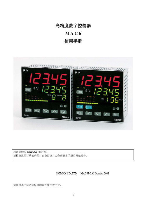
MAC6中文说明书
3-3 订货信息
项目 型号 输入
代码 MAC6A-
调节输出 1
电源
规格 96×96mm 5 位数字显示高精度字控制器 M 自由输入、TC、RTD、mV、V、mA
C 继电器接点 1a 240V AC 2A( 阻性负载 ) S 固态继电器(SSR)驱动 12V DC 最大20mA I 电流 4-20mA DC 负载电阻最大500Ω V 电压 0-10V DC 负载电流最大2mA Y 控制电机 (伺服控制输出)接点容量1C 240V AC 2A X 控制电机 (伺服控制输出)SSR 240V AC 2A
3
生电磁干扰。请在采取有效措施后使用。 ● 仪器具有用于散热的通风口,并且确保金属不会进入通风口中,否则会引起故障或者火灾。 ● 不要阻塞通风口或者使尘埃和其他类似物附着在上面,温度升高或者绝缘失效都会缩短产品寿命并
引起火灾。 ● 应该注意在重复性极限值(如电压、噪声、浪涌)实验时可能会损坏设备。 ● 禁止使用者改型和不正当使用。 3 简介 3-1 使用前的检查
在使用 MAC6 前请检查型号代码、外观和附件。确认没有错误、损坏和丢失。 确认型号代码,检查与订货的产品一致。根据下述代码表检查机壳上的型号代码。 检查附件 「注」 如果您有任何问题请联系我们的代理商或者营业本部。我们欢迎任何询问,例如,产品缺
陷、附件丢失等。
「 注意 」
3-2 使用注意事项 ●不要用硬的、尖的物体操作前面板。不要用指甲尖触碰按键。 ●当清洁仪器时,用干布轻擦。不要使用溶剂,如,稀释剂。
7. 功能的补充说明・・・・・・・・・・・・・・・・・・・・・・・・・・・・・・・・・・・・・・・・・・・・・・・・・・・・・・・・・・・・・・・60
7-1 自动返回功能・・・・・・・・・・・・・・・・・・・・・・・・・・・・・・・・・・・・・・・・・・・・・・・・・・・・・・・・・・・・・60 7-2 输出软启动功能・・・・・・・・・・・・・・・・・・・・・・・・・・・・・・・・・・・・・・・・・・・・・・・・・・・・・・・・・・・60 7-3 事件报警方式・・・・・・・・・・・・・・・・・・・・・・・・・・・・・・・・・・・・・・・・・・・・・・・・・・・・・・・・・・・・・60 7-4 AT(自整定)・・・・・・・・・・・・・・・・・・・・・・・・・・・・・・・・・・・・・・・・・・・・・・・・・・・・・・・・・・・・・60
- 1、下载文档前请自行甄别文档内容的完整性,平台不提供额外的编辑、内容补充、找答案等附加服务。
- 2、"仅部分预览"的文档,不可在线预览部分如存在完整性等问题,可反馈申请退款(可完整预览的文档不适用该条件!)。
- 3、如文档侵犯您的权益,请联系客服反馈,我们会尽快为您处理(人工客服工作时间:9:00-18:30)。
________________________________________________________________ Maxim Integrated Products
For pricing, delivery, and ordering information, please contact Maxim/Dallas Direct! at 1-888-629-4642, or visit Maxim’s website at .
PART MAX1136EUA+ MAX1136KEUA+ MAX1136LEUA+ MAX1136MEUA+ INL (LSB) ±1 ±1 ±1 ±1 MAX1137EUA+ MAX1137KEUA+ MAX1137LEUA+ MAX1137MEUA+ MAX1138EEE+ MAX1138KEEE+ MAX1138LEEE+ MAX1138MEEE+
Ordering Information
TEMP RANGE -40°C to +85°C -40°C to +85°C -40°C to +85°C -40°C to +85°C -40°C to +85°C -40°C to +85°C -40°C to +85°C -40°C to +85°C -40°C to +85°C -40°C to +85°C -40°C to +85°C -40°C to +85°C PINI2C SLAVE PACKAGE ADDRESS 8 µMAX 8 µMAX 8 µMAX 8 µMAX 8 µMAX 8 µMAX 8 µMAX 8 µMAX 16 QSOP 16 QSOP 16 QSOP 16 QSOP 0110100 0110000 0110010 0110110 0110100 0110000 0110010 0110110 0110101 0110001 0110011 0110111
Features
♦ High-Speed I2C-Compatible Serial Interface ♦ ♦ ♦ ♦ ♦ ♦ ♦ ♦ 400kHz Fast Mode 1.7MHz High-Speed Mode Single-Supply 2.7V to 3.6V (MAX1137/MAX1139) 4.5V to 5.5V (MAX1136/MAX1138) Internal Reference 2.048V (MAX1137/MAX1139) 4.096V (MAX1136/MAX1138) External Reference: 1V to VDD Internal Clock 4-Channel Single-Ended or 2-Channel Fully Differential (MAX1136/MAX1137) 12-Channel Single-Ended or 6-Channel Fully Differential (MAX1138/MAX1139) Internal FIFO with Channel-Scan Mode Low Power 670µA at 94.4ksps 230µA at 40ksps 60µA at 10ksps 6µA at 1ksps 0.5µA in Power-Down Mode Software-Configurable Unipolar/Bipolar Small Packages 8-Pin µMAX (MAX1136/MAX1137) 16-Pin QSOP (MAX1138/MAX1139)
Stresses beyond those listed under “Absolute Maximum Ratings” may cause permanent damage to the device. These are stress ratings only, and functional operation of the device at these or any other conditions beyond those indicated in the operational sections of the specifications is not implied. Exposure to absolute maximum rating conditions for extended periods may affect device reliability.
MAX1136–MAX1139
♦ ♦
Applications
Hand-Held Portable Applications Medical Instruments Battery-Powered Test Equipment Solar-Powered Remote Systems Received-Signal-Strength Indicators System Supervision
+Denotes lead-free package. Ordering Information continued at end of data sheet. Pin Configurations and Typical Operating Circuit appear at end of data sheet. 1
元器件交易网
2.7V to 3.6V and 4.5V to 5.5V, Low-Power, 4-/12-Channel, 2-Wire Serial 10-Bit ADCs MAX1136–MAX1139
ABSOLUTE MAXIMUM RATINGS
VDD to GND ..............................................................-0.3V to +6V AIN0–AIN11, REF to GND ............-0.3V to the lower of (VDD + 0.3V) and 6V SDA, SCL to GND.....................................................-0.3V to +6V Maximum Current Into Any Pin .........................................±50mA Continuous Power Dissipation (TA = +70°C) 8-Pin µMAX (derate 4.5mW/°C above +70°C) .............362mW 16-Pin QSOP (derate 8.3mW/°C above +70°C)........666.7mW Operating Temperature Range ...........................-40°C to +85°C Junction Temperature ......................................................+150°C Storage Temperature Range .............................-60°C to +150°C Lead Temperature (soldering, 10s) .................................+300°C
ቤተ መጻሕፍቲ ባይዱ
*Purchase of I2C components from Maxim Integrated Products, Inc., or one of its sublicensed Associated Companies, conveys a license under the Philips I2C Patent Rights to use these components in an I2C system, provided that the system conforms to the I2C Standard Specification as defined by Philips. AutoShutdown is a trademark of Maxim Integrated Products, Inc. µMAX is a registered trademark of Maxim Integrated Products, Inc.
Selector Guide
PART MAX1136 MAX1137 MAX1138 MAX1139 INTERNAL SUPPLY INPUT REFERENCE VOLTAGE CHANNELS (V) (V) 4 4 12 12 4.096 2.048 4.096 2.048 4.5 to 5.5 2.7 to 3.6 4.5 to 5.5 2.7 to 3.6
元器件交易网
19-2334; Rev 4; 10/06
2.7V to 3.6V and 4.5V to 5.5V, Low-Power, 4-/12-Channel, 2-Wire Serial 10-Bit ADCs
General Description
The MAX1136–MAX1139 low-power, 10-bit, multichannel analog-to-digital converters (ADCs) feature internal track/hold (T/H), voltage reference, clock, and an I2C*-compatible 2-wire serial interface. These devices operate from a single supply of 2.7V to 3.6V (MAX1137/ MAX1139) or 4.5V to 5.5V (MAX1136/MAX1138) and require only 670µA at the maximum sampling rate of 94.4ksps. Supply current falls below 230µA for sampling rates under 46ksps. AutoShutdown™ powers down the devices between conversions, reducing supply current to less than 1µA at low throughput rates. The MAX1136/MAX1137 have four analog input channels each, while the MAX1138/MAX1139 have 12 analog input channels each. The fully differential analog inputs are software configurable for unipolar or bipolar, and single ended or differential operation. The full-scale analog input range is determined by the internal reference or by an externally applied reference voltage ranging from 1V to V DD . The MAX1137/ MAX1139 feature a 2.048V internal reference and the MAX1136/MAX1138 feature a 4.096V internal reference. The MAX1136/MAX1137 are available in an 8-pin µMAX® package. The MAX1138/MAX1139 are available in a 16-pin QSOP package. The MAX1136–MAX1139 are guaranteed over the extended temperature range (-40°C to +85°C). For pin-compatible 12-bit parts, refer to the MAX1136–MAX1139 data sheet. For pin-compatible 8-bit parts, refer to the MAX1036–MAX1039 data sheet.