A10VO 0Series 30 Size 71 Service Parts list
Sugatsune 玻璃支持硬件及配件说明书

SHELF & SUPPORT HARDWAREGLASS CLAMPSGLASS SHELF SUPPORTSSOAP HOLDERSBRACKETSMIRROR SUPPORTSGLASS STANDOFFSSHELF STANDARDS & ACCESSORIESSHELVING SYSTEMSMIRROR SUPPORTS PictureSMB-15RSPM-20BSP-1820(HEAVY DUTY)SPN-1820(NARROW PROFILE)496SPE-FB20S330lbs/4pcsSPHL-25SPN-15FSL-MBFSL-LSPN-17ECSPH-20SPH-5286lbs/4pcsSPH-1511lbs/pc SPB-35220lbs/4pcs 99lbs/4pcs 176lbs/4pcsSPF-20SPB-15R SPB-20SPW-20Item No.Glass Thickness (mm)Weight (g)Box (pcs)Carton (pcs) 9303VA21032410100Material Finish 316 Stainless Steel SatinItem No.Glass Thickness (mm)Weight (g)Box (pcs)Carton (pcs) 9344VA21022910100Material Finish316 Stainless Steel Satin • 316 stainless steel clamp.• F or flat surface.• O ptional Parts: 4820VA (Safety Pin)• S ee page 466 for load capacity.• T empered Glass Recommended.• 316 stainless steel clamp.• F or flat surface.• O ptional Parts: 9320VA (Safety Pin)4849VA (Safety Plate)• S ee page 466 for load capacity.• T empered Glass Recommended.GLASS CLAMP9303VA2 GLASS CLAMP9344VA2ZN1ZN1ZN5Item No.4846ZN14846ZN5GLASS CLAMPZN1ZN1ZN1 ZN54846ZN5 (P.463)Item No.Glass Thickness (mm)2878ST86~10MOUNTING SCREWMS7 MS15ZN1ZN5ZN1ZN5ZN1Item No.D LDSP-S/1212 (15/32")120 ( 4-45/64" ) DSP-S/1512 (15/32")150 ( 5-57/64" ) DSP-S/2012 (15/32")200 ( 7-55/64" ) DSP-M/1514 (35/64")150 ( 5-57/64" ) DSP-M/2014 (35/64")200 ( 7-55/64" ) DSP-M/2414 (35/64")240 ( 9-7/16" ) DSP-M/3014 (35/64")300 (11-51/64") DSP-L/2020 (25/32")200 ( 7-55/64" ) DSP-L/2520 (25/32")250 ( 9-53/64" )SU-B80/MSU-B65/MSU-B50/MXL-SA01-120/SXL-SA01-150/SXL-SA01-180/SXL-SA01-240/SStainless Steel WhiteBlackApplication ExampleEBDFolding BracketDamper unit477.21-3/16"(30 mm)12-1/2" (317 mm)P1*6-3/4" (171 m m )1/16"(2 m m )15/16"(24 m m )2-5/8"(67 m m )1-3/4"(45 m m )1-1/2"(38 m m )6-1/8" (156 mm)3-7/8"(98 mm)1-7/16"(36 mm)1-7/16"(36 m m )FOLDING BRACKET WITH SOFT-CLOSETo find your Min./Max. table weight per single damper, please reference the formula shown next to the charts above and 18” depth examples below.EB-303/EP-DMaximum weight 7.2 lbs = 130/18 in.Minimum weight 2.8 lbs = 52/18 in.EB-317/EP-DMaximum weight 19.1 lbs = 345/18 in.Minimum weight 12.5 lbs = 225/18 in.Stainless SteelBlackTT EB-317/EP-D• A utomatically locks when flap is in open position.• P ress lever to release the lock.• A dditional hinges not required.• D amper unit with a soft-closing feature which makes bracket smoother and safer.• R efer to DAMPER WEIGHT CHART below for appropriate table weight and depth when softly folding down the table. • F or panel thickness 9/16" ~ 1-3/8" (15 ~ 35 mm).• D urability tested 50,000 cycles (private).Side Levers Connecting RodSafety Lock ScrewHolding BracketSpringConnecting LeverFor EB-2000-3 onlyNo.Part Name Material Finish1Connecting LeverAluminum AnodizedAluminum 2Side Lever3Spring Stainless Steel4Washer Plastic5Holding BracketAluminum AnodizedAluminum 6Connecting RodStainless Steel477.4Item No.Rod QtyRod Length (L)Side Lever QtySafety Lock QtyHolding Bracket QtySpring QtyEB-1000-2139-3/8" (1000 mm)2131EB-1500-2159-1/16" (1500 mm)2131Item No.Rod QtyRod Length (L)Side Lever QtyConnecting Lever QtySafety Lock Qty Holding Bracket Qty Spring QtyEB-2000-3239-3/8" (1000 mm) each 21161Connecting LeverLEVER RELEASE FOR EB SERIES FOLDING BRACKETSLEVER RELEASE for EB Folding Bracket LEVER RELEASE for EB Folding Bracket EB-1000-2/1500-2EB-2000-3SHELF & SUPPORT HARDWARERecommended Hinge: 388H38830-25-DDamper388HDo not lift up the shelf forcibly. It may result in breakage.Z058* S pecial wrench Z058 required for installation. (Sold Separately)Cut Out DimensionCut Out DimensionMaterialFinish 302 Stainless Steel/Aluminum SatinItem No.Glass Thickness (mm)Weight (g)Box (pcs)Carton (pcs)7005VA 8~12192440MaterialFinish 302 Stainless Steel/Aluminum SatinItem No.Glass Thickness (mm)Weight (g)Box (pcs)Carton (pcs)7000VA 8~12167440Z058• F lush mount type glass standoff.• R ecommended Screw Size: M8 bolt • L onger base 80~180 mm (3-5/32"~7-3/32") available as special order.• R ecommended for use with tempered glass.* S pecial wrench Z058 required for installation. (Sold Separately)• G lass standoff with round face plate.• R ecommended Screw Size: M8 bolt • L onger base 80~180 mm (3-5/32"~7-3/32") as special order.• R ecommended for use with tempered glass.GLASS STANDOFF 7000VAGLASS STANDOFF 7005VAItem No.Glass Thickness (mm) Item No.Glass Thickness (mm) 7015VA8~12Item No.Glass Thickness (mm)7061VA6~12GLASS STANDOFF Item No.Glass Thickness (mm)7062VA6~12Z057* S pecial wrench Z057 required for installation. (Sold Separately)Item No.Glass Thickness (mm)7083VA 6~12Finish GLASS STANDOFFItem No.Glass Thickness (mm)7120VA8GLASS STANDOFFSMB-15RSPM-20BSP-1820(HEAVY DUTY)SPN-1820(NARROW PROFILE)496SPE-FB20S330lbs/4pcsSPHL-25SPN-15FSL-MBFSL-LSPN-17ECSPH-20SPH-5286lbs/4pcsSPH-1511lbs/pc SPB-35220lbs/4pcs 99lbs/4pcs 176lbs/4pcsSPF-20SPB-15R SPB-20SPW-20Item No.Item No.Load Capacity (kg)SPH-15130 (286 lbs)/4 pcs END CAPWeight (g)1.3StandardAP-DM1820WT AP-DM1820AP-DH1820Item No.D E Weight (g)AP-DM1820178017113 AP-DM1820WT AP-DM1820BL AP-DM2600250047161 AP-DH1820178017131 AP-DH2600250047187Item No.Screw TypeAP-SC3-16 AP-SC3-16WT AP-SC3-16BL AP-SC3-30 AP-SC3-30WT AP-SC3-30BL • A luminum shelf standard.• E asy to cut to desired length.• T hin profile (3 mm, 1/8") suitable for surface mount.• S crew hole located every 120 mm (4-23/32").• N ew slot shape to prevent shelf support from falling off.• S pecial screw with silver finish available. (AP-SC3-16)• S crews and accessories sold separately.• A luminum shelf standard.• E asy to cut to desired length.• D esigned for press-fit mount without using screws.• N ew slot shape to prevent shelf support from falling off.• S crews and accessories sold separately.* Install the standard with concave slot(located every 120 mm) pointing upward.* Fit tightness may vary depending on the panel/wall material. Use adhesive if loose.Bore Dimension (In case of Plywood)SHELF STANDARDHolds in any height。
多功能机械辅助系统安装维护与配件手册说明书

For other service manuals visit our website at:/service_manuals.aspDORNER MFG. CORP .INSIDE THE USA OUTSIDE THE USA P .O. Box 20 • 975 Cottonwood Ave.TEL: 1-800-397-8664TEL: 262-367-7600Hartland, WI 53029-0020 USA FAX: 1-800-369-2440FAX: 262-367-5827851-260 Rev. J2100, 2200, 4100, 6200 and MPB Series Bottom Mount Drive Package for Light Load60 Hz GearmotorsInstallation Maintenance & Parts ManualDorner Mfg. Corp.2851-260 Rev. J2100, 2200, 4100, 6200 and MPB Series Bottom Mount Drive Package for Light Load 60 Hz Gearmotors Table of ContentsIntroduction......................................................................... 2Warnings − General Safety ................................................. 3Product Description............................................................. 4Specifications...................................................................... 4Installation........................................................................... 7Required Tools................................................................. 7Mounting.......................................................................... 7Preventive Maintenance and Adjustment.......................... 10Required Tools............................................................... 10Timing Belt Tensioning. (10)Timing Belt Replacement .............................................. 10Drive or Driven Pulley Replacement ............................ 11Gearmotor Replacement ................................................ 11Service Parts....................................................................... 142100, 2200, 4100, 6200 Series and MPB SeriesLight Load Bottom Mount Drive Package .................... 144100 Series Adapter Package ........................................ 15Gearmotors..................................................................... 15Return Policy. (16)IntroductionUpon receipt of shipment:•Compare shipment with packing slip. Contact factory regarding discrepancies.•Inspect packages for shipping damage. Contact carrier regarding damage.•Accessories may be shipped loose. See accessory instruc-tions for installation.Dorner 2100 Series conveyors are covered by the following patent numbers: 5131529, 5174435, and corresponding patents and patent applications in other countries.Dorner 2200 and MPB Series conveyors are covered by patent number 5174435 and corresponding patents and patent applications in other countries.Dorner 4100 Series conveyors are covered by patent number 3923148 and corresponding patents and patent applications in other countries.Dorner 6200 Series conveyors are covered by patent number 6685009, 5174435, 6109427 and corresponding patents and patent applications in other countries.Dorner’s Limited Warranty applies.Dorner reserves the right to make changes at any time without notice or obligation.Dorner has convenient, pre −configured kits of Key Service Parts for all conveyor products. These time saving kits are easy to order, designed for fast installation, and guarantee you will have what you need when you need it. Key Parts and Kits are marked in the Service Parts section of this manual with the Performance Parts Kits logo .IMPORTANTSome illustrations may show guardsremoved. Do NOT operate equipment without guards.851-260 Rev. J3Dorner Mfg. Corp.2100, 2200, 4100, 6200 and MPB Series Bottom Mount Drive Package for Light Load 60 Hz Gearmotors Warnings − General SafetyA WARNINGThe safety alert symbol, black triangle with white exclamation, is used to alert you to potential personal injury hazards.Climbing, sitting, walking or riding onconveyor will cause severe injury. KEEP OFFCONVEYORS.DO NOT OPERATE CONVEYORS IN AN EXPLOSIVE ENVIRONMENT.Hazardous voltage will cause severe injury ordeath. LOCK OUT POWER BEFORE WIRING.A WARNINGGearmotors may be HOT.DO NOT TOUCH Gearmotors.A WARNINGExposed moving parts can cause severe injury. LOCK OUT POWER before removingguards or performing maintenance.A WARNINGDorner cannot control the physicalinstallation and application of conveyors. Taking protective measures is the responsibility of the user.When conveyors are used in conjunction with other equipment or as part of a multiple conveyor system, CHECK FOR POTENTIAL PINCH POINTS and other mechanical hazards before system startup.A WARNINGMPB Series Conveyors are not reversible. Reversing creates pinch points which can cause severe injury.DO NOT REVERSE MPB SERIES CONVEYORS.Dorner Mfg. Corp.4851-260 Rev. J2100, 2200, 4100, 6200 and MPB Series Bottom Mount Drive Package for Light Load 60 Hz Gearmotors Product DescriptionRefer to Figure 1 for typical components.Figure 1SpecificationsGearmotor Mounting Package Models:Example:* See “Ordering and Specifications” Catalog for details.A ConveyorB Mounting BracketC GearmotorD Belt TensionerE CoverF Timing BeltG Drive Pulley HDrivenPulleyABCDEFGH Single PhaseDC Variable Speed Output Power 0.03 hp (0.025 kw)0.06 hp (0.04 kw)Input Voltage 115 Volts A.C.130 Volts D.C.Input Frequency 60 Hz N/AFull Load Amperes 0.49 Amperes 0.48 Amperes Gearmotor Ratios15:1 and 36:118:1 and 60:1851-260 Rev. J5Dorner Mfg. Corp.2100, 2200, 4100, 6200 and MPB Series Bottom Mount Drive Package for Light Load 60 Hz Gearmotors SpecificationsTable 2: Belt Speeds for Light Load Fixed Speed Parallel Shaft 60 Hz Gearmotors on 2100, 2200 Gang Drive, 4100 and 6200 Series Conveyors* 115V , 1 phase, non −reversingTable 3: Belt Speeds for Light Load Fixed Speed Parallel Shaft 60 Hz Gearmotors on 2200 Series Conveyors (Excluding Gang Drive)* 115V , 1 phase, non −reversingTable 4: Belt Speeds for Standard Load Fixed Speed Parallel Shaft 60 Hz Gearmotors on MPD Series Conveyors* 115V , 1 phase, non −reversingTable 5: Belt Speeds for Light Load Variable Speed Parallel Shaft DC Gearmotors on 2100, 4100 and 6200 Series Conveyors* 130VDCGearmotors *Belt Speed Drive Pulley Driven Pulley Part Number Gear RatioRPM In-lb N-m Ft/min M/min 62M036PL4FN 36:14236 4.18 2.4223262M036PL4FN 36:14236 4.112 3.7323262M036PL4FN 36:14236 4.117 5.2322262M036PL4FN 36:14236 4.1247.3442262M015PL4FN 15:110015 1.7298.8323262M015PL4FN15:1100151.74112.53222Gearmotors *Belt Speed DrivePulley Driven Pulley Part Number Gear RatioRPM In-lb N-m Ft/min M/min 62M036P L 4FN 36:14236 4.1 134.0283262M036PL4FN 36:14236 4.115 4.6282862M036PL4FN 36:14236 4.121 6.4322262M036PL4FN 36:14236 4.1298.8442262M015PL4FN 15:110015 1.73510.7282862M015PL4FN15:1100151.75516.84428Gearmotors *Belt Speed Drive Pulley Driven Pulley Part Number Gear RatioRPM In-lb N-m Ft/min M/min 62M036PL4FN 36:14236 4.1257.5283262M036PL4FN 36:14236 4.1288.6282862M036PL4FN 36:14236 4.14513.6442862M036PL4FN36:142364.15717.34422Gearmotors *Belt Speed Drive Pulley Driven Pulley Part Number Gear RatioRPM In-lb N-m Ft/min M/min 62M060PLD3DEN 60:142657.4 1.0−8.2.3−2.5223262M060PLD3DEN 60:142657.4 1.4−12.4−3.6323262M018PLD3DEN 18:113921 2.4 4.8−40 1.5−12323262M018PLD3DEN18:1139212.47−582.1−183222Dorner Mfg. Corp.6851-260 Rev. J2100, 2200, 4100, 6200 and MPB Series Bottom Mount Drive Package for Light Load 60 Hz Gearmotors SpecificationsTable 6: Belt Speeds for Standard Load Variable Speed Parallel Shaft DC Gearmotors on 2200 Series Conveyors (Excluding Gang Drive)Table 7: Belt Speeds for Standard Load Variable Speed Parallel Shaft DC Gearmotors on MPB Series Conveyors* 130VDCGearmotors *Belt Speed Drive Pulley Driven Pulley Part Number Gear RatioRPM In-lb N-m Ft/min M/min 62M060PLD3DEN 60:142657.4 1.8−14.5−4.5282862M060PLD3DEN 60:142657.4 2.8−23.8−7442862M018PLD3DEN 18:113921 2.46−49 1.8−15282862M018PLD3DEN18:1139212.49−772.8−234428Gearmotors *Belt Speed Drive Pulley Driven Pulley Part Number Gear RatioRPM In-lb N-m Ft/min M/min 62M060PLD3DEN 60:142657.4 2.3−19.7−5.9223262M060PLD3DEN 60:142657.4 3.4−281−8.6282862M060PLD3DEN 60:142657.4 5.3−44 1.6−13442862M018PLD3DEN 18:113921 2.411−94 3.5−28282862M018PLD3DEN18:1139212.416−1485−454428NOTEFor belt speed other than those listed, contact factory for details.851-260 Rev. J7Dorner Mfg. Corp.2100, 2200, 4100, 6200 and MPB Series Bottom Mount Drive Package for Light Load 60 Hz Gearmotors InstallationRequired Tools•Hex key wrenches: 2.5 mm, 3 mm & 5 mm •Torque wrenchInstallation Component List:Mounting1.Typical components (Figure 2)Figure 22.Locate drive output shaft (Figure 3,item P) and remove two screws (Q).Figure 33.For your reference, the following five figures show the attachment area of complete mounting packages for the various conveyor series.2200 Series Figure 4I Bottom Mount Assembly J Driven Pulley K CoverL M4 Socket Head Screws (4x)M Timing Belt N KeyOM6 Socket Head Screws (2x)A WARNINGExposed moving parts can cause severe injury. LOCK OUT POWER before removing guards or performing maintenance.A WARNINGMPB Series Conveyors are not reversible. Reversing creates pinch points which can cause severe injury. DO NOT REVERSE MPB SERIES CONVEYORS.NOTE6200 conveyor shown, other Series similar.NKMJLOIQPDorner Mfg. Corp.8851-260 Rev. J2100, 2200, 4100, 6200 and MPB Series Bottom Mount Drive Package for Light Load 60 Hz Gearmotors Installation6200 Series Figure54100 SeriesFigure 62100 SeriesFigure 7MPB Series Figure84.Attach mount assembly (Figure 9,item I) with screws (O). Tighten screws to 80 in-lb (9 Nm).Figure95.Install key (Figure 10,item N).Figure 10A WARNINGDrive shaft keyway may be sharp.HANDLE WITH CARE.OIUNJRM851-260 Rev. J9Dorner Mfg. Corp.2100, 2200, 4100, 6200 and MPB Series Bottom Mount Drive Package for Light Load 60 Hz Gearmotors Installation6.Wrap timing belt (M) around driven pulley (J) and drive pulley (R). Install driven pulley (J) onto conveyor shaft.7.Remove cam bearing and spacer (Figure 9,item U). Place the cam bearing and spacer (Figure 11,item U) next to the driven pulley (J). Ensure the flanges of the driven pulley are aligned with the cam bearing. Tighten driven pulley set screws (T). This will allow for proper belt alignment while conveyor is in use. Replace cam bearing and spacer (U).Figure 118.Depending on direction of conveyor belt travel (1 or 2 of Figure 12), position timing belt tensioner (U) as shown. Tension timing belt to obtain 1/8” (3 mm) deflection for 1 lb (456 grams) of force at timing belt mid-point (V). Tighten tensioner screw to 106 in-lb (12 Nm).Figure 129.Install cover (Figure 13,item K) with four (4) screws (L). Tighten to 35 in-lb (4 Nm).Figure 13JT2VU1VUKLLDorner Mfg. Corp.10851-260 Rev. J2100, 2200, 4100, 6200 and MPB Series Bottom Mount Drive Package for Light Load 60 Hz Gearmotors Preventive Maintenance and AdjustmentRequired Tools•Hex key wrenches: 2.5 mm, 3 mm, 5 mm •Straight edge•Screwdriver (for terminal box screws)•Torque wrenchTiming Belt Tensioning1.Remove four (4) screws (Figure 14,item L) and remove cover (K).Figure 142.Loosen tensioner (Figure 15,item U).Figure 15 3.Depending on direction of conveyor belt travel (1 or 2 of Figure 16), position timing belt tensioner (U) as shown. Tension timing belt to obtain 1/8” (3 mm) deflection for 1 lb (456 grams) of force at timing belt mid-point (V). Tighten tensioner screw to 106 in-lb (12 Nm).Figure 164.Install cover (Figure 14,item K) with four (4) screws (L). Tighten screws to 35 in-lb (4 Nm).Timing Belt Replacement1.Remove four (4) screws (Figure 14,item L) and remove cover (K).2.Loosen tensioner (Figure 15,item U).3.Remove timing belt (Figure 17,item M).Figure 17A WARNINGExposed moving parts can cause severe injury. LOCK OUT POWER before removing guards or performing maintenance.KLLUA WARNINGExposed moving parts can cause severe injury. LOCK OUT POWER before removing guards or performing maintenance.2VU1VUTM851-260 Rev. J11Dorner Mfg. Corp.2100, 2200, 4100, 6200 and MPB Series Bottom Mount Drive Package for Light Load 60 Hz Gearmotors Preventive Maintenance and Adjustment4.Install new timing belt.5.Depending on direction of conveyor belt travel (Figure 16,item 1 or 2), position timing belt tensioner (U) as shown. Tension timing belt to obtain 1/8” (3 mm) deflection for 1 lb (456 grams) of force at timing belt mid-point (V). Tighten tensioner screw to 106 in-lb (12 Nm).6.Install cover (Figure 14,item K) with four screws (L). Tighten screws to 4 Nm.Drive or Driven Pulley Replacement1.Complete steps 1 through 3 of “Timing Belt Replacement” section on page 10.2.Loosen set screws and remove drive or driven pulley.Figure 183.Complete steps 6 through 9 of “Installation” section on page 9.Gearmotor Replacement1.For single phase motor, unplug power cord from outlet.2.For DC variable speed motor, unplug motor cord atdisconnect (Figure 19,item W).Figure 193.Remove four screws (Figure 14,item L) and remove cover (K).4.Loosen tensioner (Figure 15,item U).5.Remove timing belt (Figure 17,item M).NOTEIf timing belt does not slide over pulley flange, loosen driven pulley set screws (Figure 17,item T) and remove pulley with belt. For re-installation, see steps 6 through 9 on page 9.A WARNINGExposed moving parts can cause severe injury. LOCK OUT POWER before removing guards or performing maintenance.NOTEIf drive pulley (Figure 18,item R) is replaced, wrap timing belt (M) around drive pulley and complete step 3.RMA WARNINGExposed moving parts can cause severe injury. LOCK OUT POWER before removing guards or performing maintenance.Hazardous voltage will cause severe injury or death. LOCK OUT POWER BEFORE WIRING.NOTEIf timing belt does not slide over pulley flange, loosen driven pulley set screws (Figure 20,item T) and remove pulley with belt (M). For re-installation, see steps 6 through 9 on page 9.Dorner Mfg. Corp.12851-260 Rev. J2100, 2200, 4100, 6200 and MPB Series Bottom Mount Drive Package for Light Load 60 Hz Gearmotors Preventive Maintenance and AdjustmentFigure 206.Loosen two (2) set screws (Figure 21,item T). Remove drive pulley (R).Figure 217.Remove four screws (Figure 22,item X) and detach gearmotor.Figure 228.Mount new gearmotor with four screws (X). Tighten to 45 in-lb (5 Nm).9.Replace drive pulley (Figure 21,item R) and tighten setscrews (T).plete steps 6 through 9 of “Installation” section onpage 9.11.Replace wiring:•For a single phase motor, reverse step 1 on page 11.•For DC variable speed motor, reverse step 2 on page 11.TMRTXNotes2100, 2200, 4100, 6200 and MPB Series Bottom Mount Drive Package for Light Load 60 Hz Gearmotors851-260 Rev. J13Dorner Mfg. Corp.Dorner Mfg. Corp.14851-260 Rev. J2100, 2200, 4100, 6200 and MPB Series Bottom Mount Drive Package for Light Load 60 Hz Gearmotors Service Parts2100, 2200, 4100, 6200 Series and MPB Series Light Load Bottom Mount Drive PackageNOTEFor replacement parts other than those shown in this section, contact an authorized Dorner Service Center or the factory. Key Service Parts and Kits are identified by the Performance Parts Kits logo . Dorner recommends keeping these parts on hand.Item Part Number Description1202390M Nut, Cam Follower2450027M Drive Spacer (2100 − Cleated Belt andall 6200)450377MDrive Spacer (2100, 2200 and MPB − Flat Belt and all 4100)3450047M Cover Mounting Bracket (Flat Belt)450375MCover Mounting Bracket (Cleated Belt and MPB)4200376M Drive Guard (Flat Belt)450376M Drive Guard (Cleated Belt and MPB)5450046M Light Duty Motor Mount Plate − Short (Flat Belt, except MPB)450026MLight Duty Motor Mount Plate (Cleated Belt and MPB)6450445Spacer 7802−046Bearing8807−226Snap −out Plastic Plug9807−952Groove Pin (Used with Item 2 Only)10920545MSocket Head Screw M5x45mm − 15:1 Gearhead (Fixed Speed Gearmotor Only)920555MSocket Head Screw M5x55mm − 36:1 Gearhead (Fixed Speed Gearmotor Only)920416MSocket Head Cap Screw M4x16mm(Variable Speed Gearmotor Only)11980422M Square Key .4mm x 22mm (Fixed Speed Gearmotor)912−084Square Key .125” x .75” (Variable Speed Gearmotor)12920406M Socket Head Screw M4 x 6mm 13920408M Socket Head Screw M4 x 8mm 14920625M Socket Head Screw M6 x 25mm (2100)920622M Socket Head Screw M6 x 22mm (2200 Cleated Belt)920618M Socket Head Screw M6 x 18mm (4100)920630MSocket Head Screw M6 x 30mm (2200 Flat Belt and all 6200)15920840M Socket Head Screw M8 x 40mm 16980422M Square Key 4mm x 22mm 912−084Square Key .125” x .75” (1” Wide Conveyor − 4100 Only)17814-105Timing Belt, 15mm W x 460mm L 814-065Timing Belt, 15mm W x 475mm L 814-101Timing Belt, 15mm W x 500mm L 814-108Timing Belt, 15mm W x 520mm L 18450366MP Driven Pulley, 22Tooth, 12mm bore 450367MP Driven Pulley, 28Tooth, 12mm bore 450368MPDriven Pulley,32Tooth, 12mm boreItem Part Number Description851-260 Rev. J15Dorner Mfg. Corp.2100, 2200, 4100, 6200 and MPB Series Bottom Mount Drive Package for Light Load 60 Hz Gearmotors Service Parts4100 Series Adapter PackageGearmotors19450384MP Drive Pulley, 22T ooth, 10mm bore 450385MP Drive Pulley, 28T ooth, 10mm bore 450386MP Drive Pulley, 32T ooth, 10mm bore 450387MP Drive Pulley, 44T ooth, 10mm bore 450556P Drive Pulley, 22T ooth, 0.5” bore 450556P Drive Pulley, 28T ooth, 0.5” bore 450556P Drive Pulley, 32T ooth, 0.5” bore 450556PDrive Pulley, 44T ooth, 0.5” boreItem Part No.Part Description1609486Mounting Block 1” (25mm)609487Mounting Block 2” (51mm)609488Mounting Block 3” (76mm)609479Mounting Block 4” (102mm)609480Mounting Block 5” (127mm)609481Mounting Block 6” (152mm)609482Mounting Block 7” (178mm)609483Mounting Block 8” (203mm)609484Mounting Block 10” (254mm)609485Mounting Block 12” (305mm)2613602P Bolt & Flat Washer Assembly 3450374Drive Adapter Plate 4910−126Hex Nut with Lock Washer 5930612MFlat Head Screw M6 x 12mmItem Part NumberDescriptionItem Part No. Part Description162M036PL411FN Gearmotor, 0.03 hp, 115 Volts, 42RPM, 60 Hz, 1-Phase, 36:162M015PL411FNGearmotor, 0.03 hp, 115 Volts, 100 RPM, 60 Hz, 1-Phase, 15:162M060PLD3DEN Gearmotor, 0.06 hp, 130 Volts, 42 RPM, DC, 60:162M018PLD3DEN Gearmotor, 0.06 hp, 130 Volts, 139 RPM, DC, 18:12980422M Key, 4mm x 22mm, 10mm Bore 912−052Key, 1/8” x 5/8”, 1/2” Bore851-260 Rev. J Printed in U.S.A.Dorner Mfg. Corp. reserves the right to change or discontinue products without notice. Allproducts and services are covered inaccordance with our standard warranty. All rights reserved. © Dorner Mfg. Corp. 2006DORNER MFG. CORP.975 Cottonwood Ave., PO Box 20 Hartland, WI 53029-0020 USAUSATEL 1-800-397-8664 (USA)FAX 1-800-369-2440 (USA)Internet: Outside the USA:TEL 1-262-367-7600FAX 1-262-367-5827Return PolicyReturns must have prior written factory authorization or they will not be accepted. Items that are returned to Dornerwithout authorization will not be credited nor returned to the original sender. When calling for authorization, please have the following information ready for the Dorner factory representative or your local distributor:1. Name and address of customer.2. Dorner part number(s) of item(s) being returned.3. Reason for return.4. Customer's original order number used when ordering the item(s).5. Dorner or distributor invoice number.A representative will discuss action to be taken on the returned items and provide a Returned Goods Authorization number for reference.There will be a return charge on all new undamaged items returned for credit where Dorner was not at fault. Dorner is not responsible for return freight on such items.Conveyors and conveyor accessories Standard catalog conveyors 30%MPB Series, cleated and specialty belt conveyors 50%7400 & 7600 Series conveyors non-returnable items Engineered special products case by case Drives and accessories 30%Sanitary stand supports non-returnable items PartsStandard stock parts30%MPB, cleated and specialty beltsnon-returnable itemsReturns will not be accepted after 60 days from original invoice date.The return charge covers inspection, cleaning, disassembly, disposal and reissuing of components to inventory. If a replacement is needed prior to evaluation of returned item, a purchase order must be issued. Credit (if any) is issued only after return and evaluation is complete.Dorner has representatives throughout the world. Contact Dorner for the name of your local representative. Our Technical Sales, Catalog Sales and Service Teams will gladly help with your questions on Dorner products.For a copy of Dorner's Warranty, contact factory, distributor, service center or visit our website at .For replacement parts, contact an authorized Dorner Service Center or the factory.。
A10VO 31系列

31
R L
V
1) 参见 RC 30030 2) 在项目计划过程中必须考虑下列事项:
流向 ER 电磁铁的过高电流强度 (12 V 时 I > 1200 mA 或 24 V 时 I > 600 mA ) 可能导致压力意外增大,从而导致泵或系统 损坏:
如果由于极端工作参数导致无法满足上述条件,请咨询 我们。
液压油的过滤 过滤越精细,液压油清洁度就越高,轴向柱塞单元的使用寿 命也就越长。
为了确保轴向柱塞单元的功能可靠性,有必要对液压油进行 测量总量评估,以确定固体颗粒污染的程度,进而判断其清 洁度是否符合 ISO 4406。清洁度至少应达到 20/18/15 级。 当液压油温度非常高 (90 °C 至最高 115 °C) 时,清洁度至少 应达到 ISO 4406 标准的 19/17/14 级。
16
– 短的控制时间
18
– 该泵带有通轴驱动,可承装齿轮泵或者小于等于相同规格
36
的轴向柱塞泵,即 100% 通轴驱动。
41
42
44
46
48
2/48
Bosch Rexroth AG
A10VSO 系列 31 | RC 92711/01.12
订货型号/标准产品
A10VS O
/ 31
–
01
02
03
04 05
– l l l l l K57
l l l l l l KB2 – l l l l l KB3 – – l l l l KB4 – – – l l l KB5 – – – – l l KB6 – – – – – l KB7
百斯巴特服务盘中英文对照

百斯巴特定位仪维修服务盘中英文对照对于ML4600-8型(包括VAG1995, Formel2000, ML4600-8,Millennium, 百年版)定位仪,由于设备直接带有键盘,因此可直接进入下面过程。
但对于ML4000型(包括VAG1813, ML4001,KDS)定位仪,由于其只配备了光电板,而没有键盘,所以必须另外准备一个接口为大口的键盘。
(早期计算机都使用大口键盘,现在一般都使用PS2接口的键盘,接口外形比大口键盘要小。
若找不到大口键盘,可想办法找一根大小键盘接口转接线。
)进入计算机中的DOS状态的方法如下:开机进入定位仪程序准备状态主画面之后,先按住键盘上的“Back Space”键(即向前删除一格键)不松手,然后下键盘上的“E”键,则定位仪程序退出到DOS状态,屏幕上显示为C:\ML>。
把服务盘插入计算机软驱(服务盘的写保护应该打开),开启主机电源,服务盘会自动引导启动过程(如果引导程序失效,而软盘内容可在DOS状态下读出,则请在A:>的状态下键入A:>auto,然后按回车键),最后在屏幕上出现以下画面:说明:重装软件程序能够删除掉硬盘中原来所装的定位仪程序或数据,然后把软件盘插入计算机软驱,重新启动,安装程序。
也可以不用此重装软件的程序,直接把软件盘插入计算机软驱,重新启动,安装程序。
新安装的程序会自动覆盖掉老程序。
读通讯板序列号的程序可以读出通讯板内所写的设备序列号,如果是通用通讯板,则读出结果为:universal.按0键可以退出服务程序,返回到DOS状态。
6,7,8,9为特殊功能,请勿使用。
常用的操作是2-更换传感器主板和3-更换传感器镜头。
以下一一举例。
一:更换传感器主板按键盘上的2键,程序自动进入更换传感器主板的步骤。
屏幕显示的中英文对照如下所示:二:更换传感器镜头按键盘上的3键,程序自动进入更换传感器主板的步骤。
屏幕显示的中英文对照如下所示:在操作过程中可能出现的错误提示为:三:更换通讯板:说明:更换通讯板必须使用通用通讯板。
力士乐泵资料
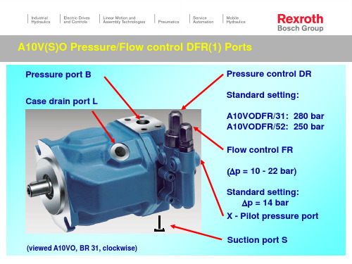
A10V(S)O Pressure/Flow control DFR(1) Usage DFR(1) for series 31 and 52 !
A10 - series 31:
DFR(1) - without return line orifice !
Slit in longitudinal direction: orifice opened
Slit in cross direction
: orifice closed, SO 74)
A10V(S)O Pressure/Flow control DFR(1) Measurement of high pressure
Eccenter
Flow control FR
(Dp = 10 - 22 bar)
Standard setting: Dp = 14 bar
X - Pilot pressure port
Suction port S
A10V(S)O Pressure/Flow control DFR(1) Circuit diagram
Valve axis: Flow control
A10V(S)O Pressure/Flow control DFR(1) Adjustment of pressure control DR
Procedure: FR - flow control blocked ! High pressure line closed ! Adjusting of DR pressure control
220
210
Dp = 15 bar
200
190
180
Rexroth 标准型力量单元说明说明书
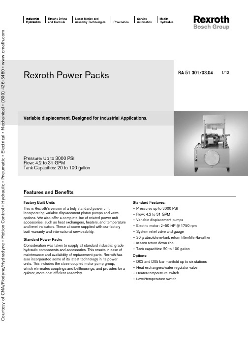
1/12Variable displacement. Designed for Industrial Applications.Pressure: Up to 3000 PSI Flow: 4.2 to 31 GPMTank Capacities: 20 to 100 gallonRA 51 301/03.04Factory Built UnitsThis is Rexroth’s version of a truly standard power unit,incorporating variable displacement piston pumps and valve options. We also offer a complete line of related power unitaccessories, such as heat exchangers, heaters, and temperature and level indicators. These all come supplied with our factory built warranty and international serviceability.Standard Power PacksConsideration was taken to supply all standard industrial grade hydraulic components and accessories. This results in ease of maintenance and availability of replacement parts. Rexroth has also incorporated some of its latest technology in its power units. This includes the close coupled motor pump group,which eliminates couplings and bellhousings, and provides for a quieter, more cost efficient assembly.Standard Features:– Pressures up to 3000 PSI – Flow: 4.2 to 31 GPM – Variable displacement pumps – Electric motor: 2–50 HP @ 1750 rpm – System relief valve and gauge– 20 µ absolute in-tank return filter/filler/breather – In-tank return down line– Tank capacities: 20 to 100 gallon Options:– D03 and D05 bar manifold up to six stations – Heat exchangers/water regulator valve – Heater/temperature switch – Level/temperature switchRexroth Power PacksFeatures and Benefitso u r t e s y o f C M A /F l o d y n e /H y d r a d y n e ▪ M o t i o n C o n t r o l ▪ H y d r a u l i c ▪ P n e u m a t i c ▪ E l e c t r i c a l ▪ M e c h a n i c a l ▪ (800) 426-5480 ▪ w w w .c m a f h .c o m2/12 Bosch Rexroth Corp. | Industrial Hydraulics Variable Displacement Power Packs | RA 51 301/03.04Model codePPV*Power Pack Variable Reservoir Size= 20= 40= 60= 100Pump SizeA10VSO 10 DR A10VSO 10 DFR A10VSO 18 DR A10VSO 18 DFR AA10VSO 28 DR AA10VSO 28 DFR AA10VSO 45 DR AA10VSO 45 DFR A10VO 71 DR A10VO 71 DFR(20 Gallon)(20 Gallon)(20 Gallon)(20 Gallon)(40 Gallon)(40 Gallon)(60 Gallon)(60 Gallon)(100 Gallon)(100 Gallon)= A = B = 1= 2= 3= 4= 5= 6= 7= 8Motor HorsepowerSee basic unit table for horsepower (hp based on reservoir & pump size)Valve OptionsRelief Valve and GaugeD03 Parallel Bar Manifold, one thru six stations w/ pressure gauge and relief D05 Parallel Bar Manifold, one thru six stations w/ pressure gauge and relief= RV= 3BMR1–6= 5BMR1–6Specify Flow & PressureLevel/Temp. Switch Options0 = None LT = Level/Temp. Switch0 =2 =3 =Heater OptionsNoneElectric Heater, 3 phase with Temperature Switch Electric Heater, single phasewith Temperature Switch 0 =1 =2 =3 =4 =Heat Exchanger OptionsNoneAir/Oil, Leakage Line Water/Oil, Leakage Line Water/Oil, Return LineAir/Oil, 3-phase Motor, Return Linewith Temperature Switch1 =2 =Pressure Gauge Option0–3000 PSI 0–5000 PSIExample: PPV403103BMR1120LT - 10 GPM / 1000 PSICircuits (see page 10 for Connection Sizes)Relief Valve Option (RV)Bar Manifold (BMR) Option with D03 or D05,with Relief Valveo u r t e s y o f C M A /F l o d y n e /H y d r a d y n e ▪ M o t i o n C o n t r o l ▪ H y d r a u l i c ▪ P n e u m a t i c ▪ E l e c t r i c a l ▪ M e c h a n i c a l ▪ (800) 426-5480 ▪ w w w .c m a f h .c o m20 Gallon Steel Reservoir: dimensions in inches (millimeters)Model CodePump Model Motor Frame Power*hp (kw)Displacement in 3/rev (cm 3/rev)Max. Flow GPM (L/min)Max. PressurePSI (bar)PPV20/ /2A10VSO10145 2.0 (1.4)0.64 (10) 4.2 (16)3000 (200)PPV20/ /3A10VSO10182 3.0 (2.2)0.64 (10) 4.2 (16)3000 (200)PPV20/ /5A10VSO10 184 5.0 (3.7)0.64 (10) 4.2 (16)3000 (200)PPV20/ /7.5A10VSO102137.5 (5.5)0.64 (10) 4.2 (16)3000 (200)PPV20/ /10A10VSO1021510.0 (7.4)0.64 (10) 4.2 (16)3000 (200)PPV20/ /2A10VSO18145 2.0 (1.4) 1.10 (18)8.0 (30)3000 (200)PPV20/ /3A10VSO18182 3.0 (2.2) 1.10 (18)8.0 (30)3000 (200)PPV20/ /5A10VSO18184 5.0 (3.7) 1.10 (18)8.0 (30)3000 (200)PPV20/ /7.5A10VSO182137.5 (5.5) 1.10 (18)8.0 (30)3000 (200)PPV20/ /10A10VSO1821510.0 (7.4)1.10 (18)8.0 (30)3000 (200)Note: Flows and pressures are factory set according to customer specifications * – Motors are closed-coupled, 3 phase, 1750, 230/460 volt, 1.15 S.F.AB A B A B AB 121212121212RA 51 301/03.04 | Variable Displacement Power Packs Industrial Hydraulics | Bosch Rexreoth Corp. 3/12o u r t e s y o f C M A /F l o d y n e /H y d r a d y n e ▪ M o t i o n C o n t r o l ▪ H y d r a u l i c ▪ P n e u m a t i c ▪ E l e c t r i c a l ▪ M e c h a n i c a l ▪ (800) 426-5480 ▪ w w w .c m a f h .c o m40 Gallon Steel Reservoir: dimensions in inches (millimeters)Model CodePump Model MotorFrame Power*hp (kw)Displacement in 3/rev (cm 3/rev)Max. Flow GPM (L/min)Max. Pressure PSI (bar)PPV40/ /5AA10VSO28 213 5.0 (3.7) 1.7 (28)12.0 (45)3000 (200)PPV40/ /7.5AA10VSO282137.5 (5.5) 1.7 (28)12.0 (45)3000 (200)PPV40/ /10AA10VSO2821510.0 (7.4) 1.7 (28)12.0 (45)3000 (200)PPV40/ /15AA10VSO2825415.0 (11.1) 1.7 (28)12.0 (45)3000 (200)PPV40/ /20AA10VSO2825620.0 (14.9) 1.7 (28)12.0 (45)3000 (200)PPV40/ /25A10VO2828425.0 (18.6)1.7 (28)12.0 (45)3000 (200)34Note: Flows and pressures are factory set according to customer specifications * – Motors are closed-coupled, 3 phase, 1750, 230/460 volt, 1.15 S.F.34343434344/12 Bosch Rexroth Corp. | Industrial Hydraulics Variable Displacement Power Packs | RA 51 301/03.04o u r t e s y o f C M A /F l o d y n e /H y d r a d y n e ▪ M o t i o n C o n t r o l ▪ H y d r a u l i c ▪ P n e u m a t i c ▪ E l e c t r i c a l ▪ M e c h a n i c a l ▪ (800) 426-5480 ▪ w w w .c m a f h .c o m60 Gallon Steel Reservoir: dimensions in inches (millimeters)Model CodePump Model MotorFrame Power*hp (kw)Displacement in 3/rev (cm 3/rev)Max. Flow GPM (L/min)Max. Pressure PSI (bar)PPV60/ /7.5AA10VSO45 2137.5 (5.5) 2.7 (45)19.5 (74)3000 (200)PPV60/ /10AA10VSO4521310.0 (7.4) 2.7 (45)19.5 (74)3000 (200)PPV60/ /15AA10VSO4525415.0 (11.1) 2.7 (45)19.5 (74)3000 (200)PPV60/ /20AA10VSO4525620.0 (14.9) 2.7 (45)19.5 (74)3000 (200)PPV60/ /25A10VO4528425.0 (18.6) 2.7 (45)19.5 (74)3000 (200)PPV60/ /30A10VO4528630.0 (22.4)2.7 (45)19.5 (74)3000 (200)565656565656Note: Flows and pressures are factory set according to customer specifications * – Motors are closed-coupled, 3 phase, 1750, 230/460 volt, 1.15 S.F.RA 51 301/03.04 | Variable Displacement Power Packs Industrial Hydraulics | Bosch Rexreoth Corp. 5/12o u r t e s y o f C M A /F l o d y n e /H y d r a d y n e ▪ M o t i o n C o n t r o l ▪ H y d r a u l i c ▪ P n e u m a t i c ▪ E l e c t r i c a l ▪ M e c h a n i c a l ▪ (800) 426-5480 ▪ w w w .c m a f h .c o m100 Gallon Steel Reservoir: dimensions in inches (millimeters)Model CodePump Model MotorFrame Power*hp (kw)Displacement in 3/rev (cm 3/rev)Max. Flow GPM (L/min)Max. Pressure PSI (bar)PPV100/ /25A10VO7128425.0 (11.1) 4.3 (71)31.0 (117)3000 (200)PPV100/ /30A10VO7128630.0 (14.9) 4.3 (71)31.0 (117)3000 (200)PPV100/ /40A10VO7132440.0 (18.6) 4.3 (71)31.0 (117)3000 (200)PPV100/ /50A10VO7132650.0 (22.4)4.3 (71)31.0 (117)3000 (200)78Note: Flows and pressures are factory set according to customer specifications * – Motors are closed-coupled, 3 phase, 1750, 230/460 volt, 1.15 S.F.7878786/12 Bosch Rexroth Corp. | Industrial Hydraulics Variable Displacement Power Packs | RA 51 301/03.04o u r t e s y o f C M A /F l o d y n e /H y d r a d y n e ▪ M o t i o n C o n t r o l ▪ H y d r a u l i c ▪ P n e u m a t i c ▪ E l e c t r i c a l ▪ M e c h a n i c a l ▪ (800) 426-5480 ▪ w w w .c m a f h .c o mPower Pack Accessory ListOption20 Gallon 40 Gallon 60 Gallon 100 Gallon 1R978808140 = Exchanger R978808140 = Exchanger R978808140 = Exchanger R978808140 = Exchanger 2R978808105 = H20 Valve R978884023 = Exchanger R978808105 = H20 Valve R978884023 = Exchanger R978808105 = H20 Valve R978884023 = Exchanger R978808105 = H20 Valve R978888744 = Exchanger 3R978808105 = H20 Valve R978888727 = Exchanger R978808106 = H20 Valve R978888738 = Exchanger R978808106 = H20 Valve R978888738 = Exchanger R978808107 = H20 Valve R978888744 = Exchanger 4R978881427 = Temp. Switch R978907474 = Exchanger R978881427 = Temp. Switch R978907475 = Exchanger R978881427 = Temp. Switch R978907476 = Exchanger R978881427 = Temp. Switch R978907477 = Exchanger 2R978881427 = Temp. Switch R978805726 = Heater 3PH, 1 kw, 480 Volt R978881427 = Temp. Switch R978805726 = Heater 3PH, 1 kw, 480 Volt R978881427 = Temp. Switch R978805727 = Heater 3PH, 2 kw, 480 Volt R978881427 = Temp. Switch R978805728 = Heater 3PH, 3 kw, 480 Volt 3R978881427 = Temp. Switch R978802712 = Heater Single PH, 1 kw, 120 VoltR978881427 = Temp. Switch R978802712 = Heater Single PH, 1 kw, 120 VoltR978881427 = Temp. Switch R978802714 = Heater Single PH, 1 kw, 120 VoltR978881427 = Temp. Switch R978802716 = Heater Single PH, 1 kw, 120 Volt**LTR978903431R978903431R978903432R978903432E l e c t r i c H e a t e r s T e m p e r a t u r eS w i t c hH e a t E x c h a n g e r s / W a t e r R e g u l a t o r V a l v e / T e m p . S w i t c h** Temperature Switch, fixed setting at 135°F, Level Switch, non-adjustable, set at low level alarm.Heat Exchanger – Option 1 (R978808140)15105H e a t D i s s i p a t i o n (h p )O i l P r e s s u r e D r o p (p s i )Oil Flow (gpm)Material: Aluminum, Cabinet SteelRA 51 301/03.04 | Variable Displacement Power Packs Industrial Hydraulics | Bosch Rexreoth Corp. 7/12o u r t e s y o f C M A /F l o d y n e /H y d r a d y n e ▪ M o t i o n C o n t r o l ▪ H y d r a u l i c ▪ P n e u m a t i c ▪ E l e c t r i c a l ▪ M e c h a n i c a l ▪ (800) 426-5480 ▪ w w w .c m a f h .c o m8/12 Bosch Rexroth Corp. | Industrial Hydraulics Variable Displacement Power Packs | RA 51 301/03.04Heat Exchanger – Options 2 and 3H e a t D i s s i pat i o n (h p )Oil Flow (gpm)9876One PassTwo Pass❶ – Hot oil in ❸ – Cooling water in ❷ – Cool oil out ❹ – Cooling water outCommon dimensions: dimensions in inches (millimeters)Rexroth Part Number A B C D E F H SAER978884023 3.85 (98)8.19 (208)10.44 (262) 2.5 (64) 2.28 (57) 1.62 (41)#12 1 1/16 - 12 UN-2B R9788887277.85 (199)12.19 (310)14.14 (363) 2.5 (64) 2.28 (57) 1.62 (41)#12 1 1/16 - 12 UN-2B R978888738 3.00 (76)8.19 (208)10.71 (272) 3.0 (76) 2.84 (72) 2.59 (66)#24 1 7/8 - 12 UN-2B R978888744 6.18 (157)12.02 (305)15.45 (392)4.0 (102)3.12 (79)4.0 (102)#32 2 1/2 - 12 UN-2BRexroth Part Number JK Dia.L M NPT N P Q NPT R9788840230.34 (9) x 0.62 (16) 2.55 (65)10.38 (263)0.75N/A 3.26 (82) 2 (1/4”)R9788887270.34 (9) x 0.62 (16) 2.55 (65)14.38 (365)0.75N/A 3.26 (82) 2 (1/4”)R9788887380.44 (11) x 0.75 (19) 3.52 (89)9.69 (246) 1.00 1.62 (41) 3.46 (87)1/4”R9788887440.44 (11) x 1.00 (25)5.05 (128)14.33 (363)1.502.38 (60)4.45 (113)1/4”o u r t e s y o f C M A /F l o d y n e /H y d r a d y n e ▪ M o t i o n C o n t r o l ▪ H y d r a u l i c ▪ P n e u m a t i c ▪ E l e c t r i c a l ▪ M e c h a n i c a l ▪ (800) 426-5480 ▪ w w w .c m a f h .c o mRA 51 301/03.04 | Variable Displacement Power Packs Industrial Hydraulics | Bosch Rexreoth Corp. 9/12Water Regulating ValveCopper Bulb 11/16 Dia.Relief Valve Option – RVSize (NPT)Rexroth Part Number A B C 3/4”R978808105 3.567.66 3.801”R978808106 4.8410.70 4.721-1/4”R9788081074.8611.084.91Max. Water Flow:SizeGPM 3/4”401”551-1/4”75Temperature:Size Range Opening Pt.3/4” – 1-1/4”75° – 135°FPart No.P1P2T1,T2G1, G2A B C D Relief ValveSize R978904345Relief Block 3/4”Code 61–12 SAE (1-1/16-12)–8 SAE (3/4-16)–4 SAE (7/16-20) 4.50(115) 2.25(57) 3.00(76) 2.68(68)DBD10R900424149R978904347Relief Block1”Code 61–16 SAE (1-5/16-12)–12 SAE (1-1/16-16)–4 SAE (7/16-20)4.50(115)2.25(57)3.00(76)2.68(68)DBD10R900424149o u r t e s y o f C M A /F l o d y n e /H y d r a d y n e ▪ M o t i o n C o n t r o l ▪ H y d r a u l i c ▪ P n e u m a t i c ▪ E l e c t r i c a l ▪ M e c h a n i c a l ▪ (800) 426-5480 ▪ w w w .c m a f h .c o m10/12 Bosch Rexroth Corp. | Industrial Hydraulics Variable Displacement Power Packs | RA 51 301/03.044.00(102)5.00(127)3.27(83)5.00(127)5BMR16.88(175)5BMR210.13(257)5BMR313.38(340)5BMR416.62(422)5BMR519.87(505)5BMR611.61(295)9.78(248)3.50(89) 3.00(76) 3.27(83)3.75(95)3BMR14.25(121)3BMR2 6.50(165)3BMR38.50(216)3BMR410.63(270)3BMR512.76(324)3BMR62.83(72)9.03(229)6.19(157)Bar Manifold Options: dimensions in inches (millimeters)3BMR5BMRo u r t e s y o f C M A /F l o d y n e /H y d r a d y n e ▪ M o t i o n C o n t r o l ▪ H y d r a u l i c ▪ P n e u m a t i c ▪ E l e c t r i c a l ▪ M e c h a n i c a l ▪ (800) 426-5480 ▪ w w w .c m a f h .c o mRA 51 301/03.04 | Variable Displacement Power Packs Industrial Hydraulics | Bosch Rexreoth Corp. 11/12In-Tank Return Line Filter Replacement CartridgePPV 20= P/N R978008660PPV 40, 60, & 100 = P/N R978008659Customer Connection Port SizesRV Option (Relief Valve w/GaugePPV 20 P = 1-1/16-12 (SAE-12)T = 1-1/16-12 (SAE-12) D = 3/4-16 (SAE-8)PPV 40 P = 1-1/16-12 (SAE-12) T = 1-5/16-12 (SAE 16) D = 1-1/16-12 (SAE-12)PPV 60 P = 1-5/16-12 (SAE-16) T = 1-5/16-12 (SAE-16) D = 1-1/16-12 (SAE-12)PPV 100 P = 1-5/16-12 (SAE-16) T = 1-7/8-12 (SAE 24)D = 1-5/16-16 (SAE-16)3BMR & 5BMR Options(D03 or D05 Parallel Bar Manifold w/Relief Valve & Gauge)3BMR1–6 X1 - X12 = 3/4-16 (SAE-8)5BMR1–6X1 - X12 = 1-1/16-12 (SAE-12)C o u r t e s y o f C M A /F l o d y n e /H y d r a d y n e ▪ M o t i o n C o n t r o l ▪ H y d r a u l i c ▪ P n e u m a t i c ▪ E l e c t r i c a l ▪ M e c h a n i c a l ▪ (800) 426-5480 ▪ w w w .c m a f h .c o mBosch Rexroth Corp.Industrial Hydraulics 2315 City Line RoadBethlehem, PA 18017-2131USATelephone (610) 684-8300Facsimile (610) © 2004 Bosch Rexroth CorporationAll rights reserved. Neither this document nor any part of it may be reproduced, duplicated circulated or disseminated, whether by copy, electronic format or any other means, without the prior consent and authorization of Bosch Rexroth Cor p o r a t ion.The data and illustrations in this brochure/data sheet are intended only todescribe or depict the products. No representation or warranty, either express or implied, relating to merchantability or fi tness for intended use, is given or intended by virtue of the information contained in this brochure/data sheet. The information contained in this brochure/data sheet in no way relieves the user of it obligation to insure the proper use of the products for a specifi c use or applica-tion. All products contained in this brochure/data sheet are subject to normal wear and tear from usage.Subject to change.12/12 Bosch Rexroth Corp. | Industrial Hydraulics Variable Displacement Power Packs | RA 51 301/03.04NotesC o u r t e s y o f C M A /F l o d y n e /H y d r a d y n e ▪ M o t i o n C o n t r o l ▪ H y d r a u l i c ▪ P n e u m a t i c ▪ E l e c t r i c a l ▪ M e c h a n i c a l ▪ (800) 426-5480 ▪ w w w .c m a f h .c o m。
iPhone A100 A101 A2105 说明书

users guideCovers models:A100,A101,A102,A103,A105,A110,A110S;A205,A205S,A210SINCLUDED IN YOUR PACKAGEHandset Line CordBase Unit Clear Plastic OverlayCoiled Handset Cord User GuideCONNECTING THE IPHONE A SERIES1)Located on the left side of the iPhone (as the phone is facing you) is a modularjack. Insert one end of the coiled handset cord into this jack (you should hear the coil cord click when properly inserted).2)Insert the other end of the coiled handset cord into the modular jack on the handset.3)Turn the telephone so the back panel is facing you. Insert either end of the line cordinto the jack on the back of the telephone labeled LINE.4)Insert the other end of the line cord into a telephone wall outlet jack.5)Once your telephone is connected, remove the plastic overlay and place the paper faceplate over the keys. Replace the plastic overlay by hooking the tabs on the overlay into the recessed slots located on both sides.PLACING A CALL USING THE HANDSET1)Lift the handset. The “LINE” LED will illuminate. (On two-line models, if both linesare inactive, line 1 will be activated. If one of the two lines is active, the inactive line will be activated.)2)Listen for dial tone. Dial the desired number, or press an AUTO DIAL key toautomatically dial a number.3)To end the call, hang up by placing the handset back in the cradle.PLACING A CALL USING THE SPEAKERPHONE(APPLIES ONLY TO MODELS WITH INCLUDED SPEAKERPHONE)1)With the handset in the cradle, press either the SPEAKER key or the LINE key (ontwo-line models, select either inactive LINE key). The telephone will go offhook on the selected line with speakerphone active.2. Listen for dial tone, and dial the desired number, or press an AUTO DIAL key toautomatically dial a number.3. To end the call, press the SPEAKER key.RECEIVING A CALLTO ANSWER A CALL USING THE HANDSET:1.Lift the handset. On two-line models, if one line is already in use, the iPhone willautomatically select the ringing line.2.To end the call hang up the handset.TO ANSWER A CALL USING THE SPEAKERPHONE1.With the handset in the cradle, press the line key associated with the ringing line.The iPhone will asnwer the line selected with the speakerphone active. You may also: 2.Press the SPEAKER key. The iPhone will select the ringing line and answer with thespeakerphone active.NOTE:THE RED SPEAKER LED WILL INDICATE THAT THE SPEAKERPHONE IS ACTIVE.1CONFERENCE (TWO-LINE-MODELS ONLY)On two-line telephones, the CONFERENCE key allows the user to include two other parties in a three-way conversation. After placing or receiving a call to/from the first party, place that party on hold by pressing the HOLD key. Using the second line, place or receive the second call. Press the CONF key to join all three callers.ADJUSTING THE SPEAKERPHONE VOLUMETo the left of the dialpad, locate the volume up/down arrow keys. With the speakerphone active, press either the up or down key to raise or lower speaker volume to the desired level.ADJUSTING THE RING VOLUMEOn the rear panel of the telephone, locate the ringer volume slide swtich. There are three settings: Low, high, and crescendo. The crescendo setting is indicated by a small triangular icon. Set the switch to the desired setting.By selecting the crescendo ringer setting, the phone will first ring at its lowest volume. With each successive ring, ringer volume will increase slightly, until, by the fourth ring, ringer volume is at the highest level. Each successive incoming call will begin at the lowest ring volume and ring accordingly.USING THE SPEAKERPHONE(SPEAKERPHONE-EQUIPPED MODELS ONLY) If you are talking on the handset and wish to transfer to the speakerphone, press the SPEAKER/HSET key, and hang up the handset in the cradle. The speakerphone will now be active.If you are talking on the speakerphone and wish to transfer to the handset, pick up the handset from the cradle. The speakerphone LED will go out and the call can be continued on the handset.USING THE HOLD KEY (TWO-LINE MODELS ONLY)TO PLACE A CALL ON HOLD1)With a call active, press the red HOLD key.2)The red line LED will change to a slow blink indicating the call is on hold.TO REMOVE A CALL FROM HOLD1)Press the line key of the call on hold. This removes the call from hold2)The red line LED will remain illuminated for the duration of the active call. CHANGING PHONES AFTER PLACING A CALL ON HOLD1)Place the call on hold, as above.2)Pick up the call at another telephone that is on the same line.234)Press an number from 0 to 5 on the dialpad. The number selected will be the pausetiming in seconds (for example: pressing the ‘3’key will insert a 3-second pause, etc.)5)Press the STORE key. The selected pause is now inserted into the dialing string. FLASH KEYThe FLASH key, when programmed behind an auto dial key, provides a timed line interrupt typically used for accessing PBX/CO features such as transfer or conference. The timing of the hookflash is programmable, with the factory default set to 600 milliseconds. Some PBXs may require you to change the hookflash timing from this default. To change the hookflash timing:1)Lift the handset or press the SPEAKERPHONE key (speakerphone-equipped models.)2)Press the STORE key (see diagram on inside front cover for key location.)3)Press the FLASH key (see diagram for key location.)4)Select 1 - 9 on the DTMF pad. The number selected will be the new flash timing inhundreds of milliseconds (ie: pressing the ‘3’key will reset the flash to 300 ms, etc.) 5)Press the STORE key. The selected flash timing is now programmed. CONVERTING FROM DESK TO WALL MOUNTThe iPhone can be converted for wall mounting applications. The conversion is easiest when the handset and line cords are not connected.1)Located on the top of the telephone above the speaker grill is the wall/desk mount clip.Remove this clip by firmly pushing upward (towards the hookswitch).2)Flip the clip over (top to bottom) so that the protruding edge is towards the top of thephone, and reinsert into cutout. This protruding edge will hold the handset.3)Turn the telephone over so the bottom is up, facing you. Place the telephone on anon-abrasive surface to prevent scratching.4)Locate and remove the mounting bracket, firmly push back and pull up to remove twoof the four retaining tabs.5)Rotate the mounting bracket 180º degrees clockwise so that the mounting eyelet onthe bracket is facing in the same direction as the other mounting eyelet located on the bottom of the telephone.6)Insert the top two retaining tabs of the mounting brackets into the mounting bracketslots (located near the middle of the telephone). Then firmly push down to insert the retaining tabs on the opposite side of the mounting bracket.7)Connect a short modular line cord into the jack on the back of the phone (labeledLINE). Route the line cord through the line cord channel. Connect the other end of line cord to the phone jack on the wall mounting plate.8)Turn the telephone over, and slide the telephone down onto the mounting posts indownward direction. Both eyelets should line up with the mounting posts.9)Complete the wall mounting by installing the handset and handset cord.45Copyright ©2005 T eledex LLC. All rights reserved. 606-2700-88。
Voice Services和Video Services产品及服务价格清单说明书
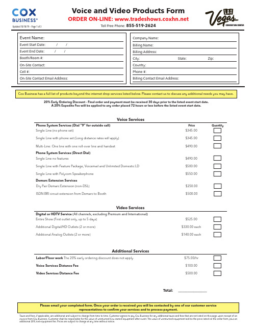
Voice ServicesPhone System Services (Dial “9” for outside call)PriceQuantitySingle Line (no phone set)$345.00c Single Line with phone set (Long distance rates will apply)$345.00c Multi-Line: One line with one roll-over line and handset $490.00c Phone System Services (Direct Dial)Single Line no features$490.00c Single Line with Feature Package, Voicemail and Unlimited Domestic LD $500.00c Single Line with Polycom Speakerphone $550.00c Demarc Extension Services Dry Pair Demarc Extension (non-DSL)$250.00c ISDN BRI circuit extension from Demarc to Booth$500.00cVideo ServicesDigital or HDTV Service (All channels, excluding Premium and International )Entire Show (First outlet only, up to 5 days)$525.00c Additional Digital/HD Outlets (2 or more)$330.00 each c Additional Analog Outlets (2 or more)$140.00 eachcAdditional ServicesLabor/Floor work The 20% early ordering discount does not apply. $75.00/hr c Voice Services Distance Fee $100.00c Video Services Distance Fee$500.00cTotal:___________________20% Early Ordering Discount – Final order and payment must be received 30 days prior to the listed event start date.A 20% Expedite Fee will be applied to any order placed 72 hours or less before the listed event start date.Taxes and fees, if applicable, are additional and subject to change from time to time. Customer agrees to pay Cox Business for any additional taxes and fees that are not listed on this page upon receipt of anBooth Diagram Information - Voice and VideoPlease indicate on the grid, the location of your Voice and Video drop(s).If no location is indicated, Voice and Video drop(s) will be placed in the middle back of the booth.This booth diagram or a detailed floor plan must be submitted with your orderAdjacent Booth #________________A d j a c e n tB o o t h #________________Adjacent Booth #________________Adjacent Booth #________________TERMS AND CONDITIONS OF SERVICE1. Service and I nstallation Cox Communications Las Vegas, I nc. d/b/a Cox Business (“Cox”), shall provide Customer with certain services (“Services”) and equipment (“Equipment”) as described on the first page for the use of Customer and Customer’s agents, independent contractors and guests attending or participating in an event hosted by Customer (“Customer’s Guest”). Customer understands that Cox is the exclusive provider of all Voice, Data and Video services at the Las Vegas Convention Center and Cashman Center (collectively, the “Facility”). Furthermore, Cox is the exclusive provider at the Facility of all floor work associated with the extension of telecommunications and networking services, including, without limitation, coax, fiber or any cabling that transmits voice, data or video. Customer shall be responsible for the acts of Customer’s Guests in connection with the Services as if such acts were performed by Customer. Except to the extent caused by Cox, a Cox agent or subcontractor, Customer shall be responsible for damage to any Equipment provided hereunder. Neither Customer nor any Customer Guest may use the Services in any manner that interferes with or impairs any Cox network, whether wired or wireless, Equipment or facilities. The Equipment may be used only for the purpose of receiving the Services. For Cox Internet services, bandwidth speed options may vary. Customer acknowledges and agrees that Customer and Customer’s Guests may not always receive or obtain optimal bandwidth speeds and Cox network management needs may require Cox to modify upstream and downstream speeds.2. Service Date and Term This Agreement shall be effective upon execution by the parties. Services shall be provided beginning on the Event Start Date and ending on the Event End Date, as described on the first page of this Agreement. Cox shall use reasonable efforts to make the Services available by the Event Start Date; provided, however, that Cox shall not be liable for any damages whatsoever resulting from delays in meeting any service dates due to delays beyond its reasonable control.3. Customer Responsibilities Customer shall ensure that Customer and Customer’s Guests use the Services in compliance with all applicable laws and ordinances, as well as applicable leases and other contractual agreements between Customer and third parties. If Customer is purchasing access codes enabling Customer or Customer’s Guests to access the Internet, such individuals will be required to agree to the terms of a Cox end user license agreement before accessing the Internet. If Customer is purchasing bandwidth and itself controlling access to the I nternet, Customer agrees to require all individuals accessing the I nternet to agree to the terms of an end user license agreement reasonably acceptable to Cox. Customer is responsible for ensuring that all Customer and Customer Guest equipment is compatible for the Services selected and with the Cox network.4. Equipment Unless otherwise provided herein, Customer agrees that Cox shall retain all rights, title and interest to facilities and Equipment installed by Cox hereunder and that Customer shall not create or permit to be created any liens or encumbrances on such Equipment. Cox shall install Equipment necessary to furnish the Services to Customer. Customer shall not modify or relocate Equipment installed by Cox without the prior written consent of Cox. Customer shall not permit tampering, altering or repair of the Equipment by any person other than Cox’s authorized personnel. For Cox-owned Equipment, Customer shall, at the expiration or termination of this Agreement, return the Equipment in good condition, ordinary wear and tear resulting from proper use excepted. In the event the Equipment is not returned to Cox in good condition, Customer shall be responsible for the value of such Equipment as provided on the first page of this Agreement, or if no such value is provided, for the replacement cost of such Equipment. Cox shall repair any Equipment owned by Cox at no charge to Customer provided that damage is not due to the negligence or intentional misconduct of Customer. If additional equipment not listed on the first page of this Agreement, including but not limited to, televisions, monitors, computers, circuits, software or other devices, are required by Customer to use the Services, Customer shall be responsible for such equipment.5. Resale of Service Neither Customer nor any Customer Guest may resell any portion of the Services to any other party.6. Default If Customer or any Customer Guest fails to comply with any material provision of this Agreement, including, but not limited to failure to make payment as specified, then Cox, at its sole option, may elect to pursue one or more of the following courses of action upon proper notice to Customer as required by applicable law: (i) terminate service whereupon all sums then due and payable shall become immediately due and payable, (ii) suspend all or any part of Services, and/or (iii) pursue any other remedies, including reasonable attorneys’ fees, as may be provided at law or in equity, including the applicable termination liabilities.7. Termination Cox reserves the right to require Customer to pay an early termination fee equal to 10% of the Cox services ordered, if Customer cancels an order after the order is placed, but before the installation date. No refunds will be provided to orders which are canceled after they have been installed. Wireless devices not authorized by Cox are prohibited. Use of any device that interferes with Cox’s network is prohibited. If there is signal interference, Cox may terminate this Agreement if Cox cannot resolve the interference by using commercially reasonable efforts. If Cox loses its right to sell Services at the Facility, Cox may assign this Agreement to a third party or terminate this Agreement by providing written notice to Customer and by refunding all prepaid amounts to Customer.8 LIMITATION OF LIABILITY COX SHALL NOT BE LIABLE FOR DAMAGES FOR FAILURE TO FURNISH OR INTERRUPTION OF ANY SERVICES, NOR SHALL COX BE RESPONSIBLE FOR FAILURE OR ERRORS IN SIGNAL TRANSMISSION, LOST DATA, FILES OR SOFTWARE DAMAGE REGARDLESS OF THE CAUSE. COX SHALL NOT BE LIABLE FOR DAMAGE TO PROPERTY OR FOR INJURY TO ANY PERSON ARISING FROM THE INSTALLATION OR REMOVAL OF EQUIPMENT UNLESS CAUSED BY THE NEGLIGENCE OF COX. UNDER NO CIRCUMSTANCES WILL COX BE LIABLE FOR ANY INDIRECT, INCIDENTAL, PUNITIVE, SPECIAL OR CONSEQUENTIAL DAMAGES INCLUDING LOST PROFITS ARISING FROM THIS AGREEMENT. COX’S MAXIMUM LIABILITY TO CUSTOMER ARISING UNDER THIS AGREEMENT SHALL BE THE LESSER OF $5,000.00 OR THE AMOUNT ACTUALLY PAID BY CUSTOMER FOR SERVICES HEREUNDER.9. Assignment Customer may not assign, in whole or in part, this Agreement without the prior written consent of Cox, which consent may be withheld in Cox’s discretion. Cox may assign this Agreement and Service may be provided by one or more legally authorized Cox affiliates.10. WARRANTIES EXCEPT AS PROVIDED HEREIN, THERE ARE NO AGREEMENTS, WARRANTIES OR REPRESENTATIONS, EXPRESS OR IMPLIED, EITHER IN FACT OR BY OPERATION OF LAW, STATUTORY OR OTHERWISE, INCLUDING WARRANTIES OF MERCHANTABILITY AND FITNESS FOR A PARTICULAR PURPOSE, RELATING TO THE SERVICES. SERVICES PROVIDED ARE A BEST EFFORTS SERVICE AND COX DOES NOT WARRANT THAT THE SERVICES, EQUIPMENT OR SOFTWARE SHALL BE ERROR-FREE OR WITHOUT INTERRUPTION. COX MAKES NO WARRANTY AS TO TRANSMISSION OR UPSTREAM OR DOWNSTREAM SPEEDS OF THE NETWORK.11. I NDEMNI TY Customer shall indemnify and hold Cox and its respective affiliates, subcontractors, employees and agents harmless (including payment of reasonable attorney’s fees) from and against any claims, actions or demands relating to or arising out of Customer’s or Customer’s Guests use of the Service including without limitation (i) any content or software displayed, distributed or otherwise disseminated by Customer, its employees, or Customer’s Guests or (ii) any malicious act or act in violation of any laws committed by Customer, its employees or Customer’s Guests.12. Viruses, Content, Customer I nformation Software or content obtained from the use of Service may contain viruses or other harmful features and Customer is solely responsible for protecting Customer and Customer’s guests’ networks, equipment and software through the use of firewalls, anti-virus, and other security devices. Through the use of the Service, Customer may obtain or discover content that is offensive or illegal and Customer assumes the risk and is solely responsible for its access to such content. Cox may disclose Customer information to law enforcement or to any Cox affiliate. Cox may delete any Internet traffic or e-mail that contains a virus. If Customer operates a wireless local access network in connection with the Services, Customer is solely responsible for the security of its network.13. Public Performance If Customer engages in a public performance of any copyrighted material through use of the Services provided under this Agreement, the Customer, and not Cox, shall be responsible for obtaining any public performing licenses. Any Video Service that Cox provides under this Agreement does not include a public performance license.14. Regulatory Authority-Force Majeure This Agreement and the obligations of the parties shall be subject to modification to comply with all applicable laws, regulations, court rulings, and administrative orders, as amended. In no event shall either party have any claim against the other for failure of performance if such failure is caused by acts of God, natural disasters including fire, flood, or winds, civil or military action, including riots, civil insurrections or acts of terrorists or the taking of property by condemnation.15. Miscellaneous This Agreement constitutes the entire agreement between Cox and Customer for the Services and equipment provided herein. The invalidity or unenforceability of any term or condition of this Agreement shall not affect the validity or enforceability of any other provision. Except as provided herein, this Agreement may be modified, waived or amended only by a written amendment signed by both parties. The rights and obligations of the parties under this Agreement shall be governed by the laws of the State of Nevada. The failure by either party to exercise one or more rights provided in this Agreement shall not be deemed a waiver of the right to exercise such right in the future. Notices required by this Agreement shall be in writing and shall be delivered either by personal delivery or by mail. If delivered by mail, notices shall be sent by any express mail service; or by certified or registered mail, return receipt requested; with all postage and charges prepaid. All notices and other written communications under this Agreement shall be addressed to the parties at the addresses on the first page of this Agreement, or as specified by subsequent written notice delivered by the party whose address has changed. Any provision that should by its nature survive the termination or expiration of this Agreement shall survive such termination or expiration. Cox network management needs may require Cox to modify upstream and downstream speeds. Use of the data, Internet, web conferencing/web hosting Services is subject to the “AUP” at /aboutus/policies/business-policies.cox. Certain Services are regulated by the FCC and the Nevada Public Utility Commission and subject to the “Nevada Service Guide”at /business/voice/regulatory.cox. The “General Terms” posted at /aboutus/policies/business-general-terms.cox, the AUP and the Nevada Service Guide are incorporated herein by reference. Cox, in its sole discretion, may modify, supplement or delete any portion of the General Terms, the AUP or the Nevada Service Guide from time to time, without additional notice to Customer, and any such changes will be effective upon Cox publishing such changes on the applicable website listed above. BY EXECUTING THIS AGREEMENT AND/OR USING OR PAYING FOR THE SERVICES, CUSTOMER ACKNOWLEDGES THAT IT HAS READ, UNDERSTOOD, AND AGREED TO BE BOUND BY THE GENERAL TERMS, the AUP and the Nevada Service Guide. If applicable to the Service, Customer shall pay sales, use, gross receipts, and excise taxes, access fees and all other fees, universal service fund assessments, 911 fees, franchise fees, bypass or other local, state and Federal taxes or charges, and deposits, imposed on the use of the Services. All orders are subject to approval of Cox.。
- 1、下载文档前请自行甄别文档内容的完整性,平台不提供额外的编辑、内容补充、找答案等附加服务。
- 2、"仅部分预览"的文档,不可在线预览部分如存在完整性等问题,可反馈申请退款(可完整预览的文档不适用该条件!)。
- 3、如文档侵犯您的权益,请联系客服反馈,我们会尽快为您处理(人工客服工作时间:9:00-18:30)。
s x
5
RA 06281-03-E/08.93
Variable Displacement Pump A10VO71, Series 30
Assembly Number A10V(S)O71
Item 8 8 8 8 8 8 8 8 8 9 10 11 12 12 13 13 14 14 15 16 17 17 17 17 17 17 18 18 18a 18a i 5 v u Description Adjusting Disc A10V(S)O71 (2.55 mm) Adjusting Disc A10V(S)O71 (2.60 mm) Adjusting Disc A10V(S)O71 (2.65 mm) Adjusting Disc A10V(S)O71 (2.70 mm) Adjusting Disc A10V(S)O71 (2.75 mm) Adjusting Disc A10V(S)O71 (2.80 mm) Adjusting Disc A10V(S)O71 (2.85 mm) Adjusting Disc A10V(S)O71 (2.90 mm) Adjusting Disc A10V(S)O71 (2.95 mm) Bearing-Tapered Roller Bearing-Tapered Roller Bearing-Cradle Seal-Shaft (Buna) Seal-Shaft (Viton) O-Ring (75/80 Duro Buna 2.5 x 195) O-Ring (75/80 Duro Viton 2.5 x 195) O-Ring (75/80 Duro Buna 17 x 2.0) O-Ring (75/80 Duro Viton 17 x 2.0) Seeger V-Ring Cap Screw (M14 x 40 DIN 912-10.9) Control Valve Assembly, DFR (Buna) Control Valve Assembly, DR (Buna) Control Valve Assembly, DFR1 (Buna) Control Valve Assembly, DFR (Viton) Control Valve Assembly, DR (Viton) Control Valve Assembly, DFR1 (Viton) Plug (SAE 7/8-14) (Buna) Plug (SAE 7/8-14) (Viton) O-Ring (90 Duro Buna, PRP 910) O-Ring (90 Duro Viton, PRP 910) Contained in Buna Seal Kit 5140-635-005 Contained in Viton Seal Kit 5140-635-007 Contained in Bearing Kit 5140-635-014 Included with 76107-010 Included with 76122-010 Qty 0 0 0 0 0 0 0 0 0 1 1 2 1 1 1 1 4 4 1 4 1 1 1 1 1 1 1 1 1 1 Part Number B939005-255 B939005-260 B939005-265 B939005-270 B939005-275 B939005-280 B939005-285 B939005-290 B939005-295 70109-007 70109-008 BH00902777 BH00727229 BH00764701 68111-033 68112-002 68111-026 68112-001 BH00791555 60119-160 BH00907094 BH00907095 BH00907096 BH00907371 BH00907370 BH00908384 76107-010 76122-010 68105-910 68106-910 Code
Mobile Division
E
Service Parts List
A10VO
Series 30 Size 71
RA 06281-03-E 08.93
RA 06281-03-E/08.93
Variable Displacement Pump A10VO71, Series 30
Ordering of Parts
THE REXROTH CORP. PISTON PUMP DIVISION FOUNTAIN INN S.C.
SERIAL NO. G3026063 A10VO71DFR1/30LPSC62N00 5142-004-035
PART NO. MINERAL OIL
MADE IN USA
Year
08.92
1
2
24
4
RA 06281-03-E/08.93
Variable Displacement Pump A10VO71, Series 30
Assembly Number A10V(S)O71
Item 1 1 2 2 2 3 4 4 4 4 4 4 4 4 4 4 5 5 6 6 6 6 7 8 8 8 8 8 8 8 8 8 8 s x Description Rotary Group Assembly A10V(S)O71L Rotary Group Assembly A10V(S)O71R Control-Piston Assembly Control-Piston Assembly (ASL Buna) Control-Piston Assembly (ASL Viton) Pump Housing Block-Port A10VO71/30L . 61N00 Block-Port A10VO71/30L . 62N00 Block-Port A10VO71/30L . 62K01 Block-Port A10VO71/30L . 62K02, K03, K04 Block-Port A10VO71/30L . 62K07, K08 Block-Port A10VO71/30R . 61N00 Block-Port A10VO71/30R . 62N00 Block-Port A10VO71/30R . 62K01 Block-Port A10VO71/30R . 62K02, K03, K04 Block-Port A10VO71/30R . 62K07, K08 Cradle Assembly A10V(S)O71L Cradle Assembly A10V(S)O71R Shaft-Drive 14T W/O T/Drive Shaft-Drive 14T With T/Drive Shaft-Drive Keyed W/O T/Drive Shaft-Drive Keyed With T/Drive Washer Adjusting Disc A10V(S)O71 (3.00 mm) Adjusting Disc A10V(S)O71 (2.10 mm) Adjusting Disc A10V(S)O71 (2.15 mm) Adjusting Disc A10V(S)O71 (2.20 mm) Adjusting Disc A10V(S)O71 (2.25 mm) Adjusting Disc A10V(S)O71 (2.30 mm) Adjusting Disc A10V(S)O71 (2.35 mm) Adjusting Disc A10V(S)O71 (2.40 mm) Adjusting Disc A10V(S)O71 (2.45 mm) Adjusting Disc A10V(S)O71 (2.50 mm) Contained in Rotary group Kit 5140-635-012 Contained in Rotary group Kit 5140-635-011 Qty 1 1 1 1 1 1 1 1 1 1 1 1 1 1 1 1 1 1 1 1 1 1 1 1 0 0 0 0 0 0 0 0 0 Part Number BH00911929 BH00956007 BH00910873 BH00910870 BH00916310 BH00915775 5140-542-005 5140-542-004 5140-542-006 5140-542-007 5140-542-003 5140-542-002 5140-542-001 5140-542-008 5140-542-009 5140-542-010 BH00904689 BH00903881 BH00923553 BH00923471 BH00926333 BH00926334 BH00744131 BH00939005 B939005-210 B939005-215 B939005-220 B939005-225 B939005-230 B939005-235 B939005-240 B939005-245 B939005-250 Code s x
For Rexroth to supply the correct parts for your unit, please include all of the following information along with your parts order. Model Code Serial Number Unit Number Part Name Part Number Due to modifications and improvements to our products, minor changes can occur to the parts, even though the type code may not necessarily reflect these changes. The type number and serial number will guarantee that the correct parts for your unit are suppied.