交通咨询系统
5 交通信息服务

交通信息网络—交通信息服务户佐安Email: huzuoan@西南交通大学交通运输学院一、基本概念主要内容二、交通信息服务价值 三、交通信息服务系统 四、出行交通信息服务系统一、 基本概念交通信息服务概念在广大公众出行者出行前或出行途中,为了方便他们出 行,向他们提供相关的交通信息的服务就是交通信息 服务。
它包括为驾车出行者提供路况、突发事件、施 工、沿途、气象、环境等信息;为采用公共交通方式 的出行者提供票务、营运、站务、转乘、沿途路况等 信息;据此出行者可提前安排出行计划, 变更出行路 线,使出行更安全、更便捷、更可靠。
交通信息服务形式 多向主动传递服务和单向被动信息服务 多向主动传递服务一般属于公益性的免费服务,其服 务价值是通过信息的广为传播、利用、价值倍增得以 体现。
单向被动信息服务是信息服务机构根据用户的信息需 求提供信息和服务,以营利为目的,所消耗的成本以 信息产品的价格来体现的。
交通信息服务途径(1)传统媒体信息发布 如:电视、广播、报纸、书本等 (2)移动通信信息发布 如:手机等移动终端 (3)现场LED显示屏 如:VSM、交通信号等 (4)互联网信息发布交通信息服务分类 1、按照向出行者提供信息的时机 (1)出行前的交通信息服务 (2)出行途中的交通信息服务 2、按照向出行者提供的信息内容 (1)路径诱导交通信息服务 (2)交通流诱导信息服务 (3)停车场交通信息诱导服务 (4)个性化交通信息服务二、交通信息服务价值 信息服务的价值由服务本身的价值和信息服务的 最终产品—信息的价值两部分组成。
信息服务本 身是一种社会劳动,为用户所接受和利用,所以 具备使用价值和价值。
对不同的价值主体,信息 服务有不同价值。
交通信息市场服务:把交通信息作为一种商业产 品摆放到服务市场上并给其定价再提供给信息需 求者的一种服务。
既然交通信息服务有定价,那么这种服务也就存 在盈利与非盈利之说,所以交通信息市场服务可 分为有偿的交通信息服务和无偿的交通信息服务 两种,目前无偿的交通信息服务占领主要的服务 市场。
常州96196交通服务热线7月份月报

常州96196交通服务热线7月份月报一、96196交通服务热线工作情况1.2012年7月17日下午,常州96196交通服务热线组织全体员工召开了2012年上半年工作总结会议,常州市运输管理处副处长夏俊华、信息科副科长虞朝晖出席了此次会议。
夏处对96196热线上半年工作表现给予了肯定,虞科就96196热线上半年工作进行总结并部署下半年工作,96196热线中心3名管理人员、7名组长和2名优秀话务员分别交流了自己的工作心得并对下一步工作进行规划。
会议以互相交流的形式展开,气氛活跃,取得了圆满的成功。
2. 按照年度工作目标,开展全员培训工作。
7月27日上午9:00,常州96196热线咨询投诉中心全体话务员在热线中心会议室就交通运政管理基本概念(下)等进行了业务知识测试。
经过学习和测试,全体话务员对交通运政管理等有了部分的了解和掌握,在平时96196热线受理工作中提高了现场答复能力,更好的服务于广大市民。
考试结束后由话务班长带领全体话务员学习了客运知识。
二、常州市96196交通服务热线运行概况2012年7月,常州“96196”投诉咨询中心共呼入电话6871个,接通6169个,除用户自动放弃的电话外,接通率为89.80%,平均通话时长117秒。
共做工单6235件,下派工单930件。
截至8月7日15:30,共办结6232件,未办结3件,办结率99.95%。
本级来电6119件,12345派单39件,12319平台转交62件,短信13件,网站2件。
涉及交通运输职能范围共5433件,约占总量的87.14%;涉及外单位的802件,约占总量的12.86%。
三、涉及交通系统职能范围的工单分析在涉及交通运输职能范围的5433件工单中,咨询类电话2566件,占47.23%;投诉类电话859件,占15.81%;举报类电话66件,占1.21%;建议类电话25件,占0.46%;表扬类电话208件,占3.83%;求助类电话1709件,占31.46%。
TCAS系统

ATC/TCAS面板对TCAS的控制
(4)TA(交通咨询) 此时在应答机正常工作的基础上,TCAS也正常工作,可在 需要时产生交通咨询, 但仍不能产生决断咨询。 (5)TA/RA(决断咨询) 工作方式开关置于TA/RA(决断咨询)位,应答机和TCAS 均处于全功能状态。 不同控制盒的形式以及工作方式开关的设置、名称、顺序均 可能与此有所不同,但其基本功能是相同的。 2、监视范围选择开关 有的TCAS控制盒上设置有一个监视范围选择开关,用于选 择监视范围为正常(N)、上方(ABOVE)或下方 (BELOW )。 控制盒上其它功能开关的功用与应答机相关。
TCAS虚假信号判别
正常情况下,TCAS判明有与本机存在潜在危险接近的 飞机时,会提前20-48秒钟发出交通咨询(TA)警告,在TA 发出后本机对入侵飞机连续监视大约15秒钟后,如果入侵飞 机与本机的危险接近情况仍存在,则本机的TCAS会发出垂 直方向决断咨询(RA)提醒飞行员避让。
而虚假TCAS警告出现的情况如下: (1)TA和RA之间的时间间隔很短,TA出现后很快(几秒 钟)转化为RA;(2)直接出现RA而不出现TA;(3)突然 出现TA/RA,然后TA/RA持续很短时间(一般几秒钟)消 失;(4)本机周围空域无其它飞机的情况下发出TA,可通 过地面ATC确认;(5)TCAS发出RA警告后,机组按照 TCAS提示操纵飞机爬升或下降后,TCAS仍显示入侵飞机 与本机的距离和方位始终保持不变,飞行员可通过地面ATC 确认。
TCAS虚假信号原因
ATC无法证实却在飞机上发生的TCAS虚假警告的 潜在原因和特点:
(2) 潜在原因- TCAS接收到其他飞机应答机的错误/干扰应答 信号: (f) 多路径信号: TCAS询问和/或应答机应答的多路径反射会 造成虚假的航迹出现在错误的范围内。这种事件在水域上空 低高度时发生为典型事件。 (g) 飞机编队:军方飞机编队飞行会产生双重目标现象。 (h) C模式地面交通:当发现目标显示一直随机的忽有忽无 时,这通常是地面交通工具造成的。只有当飞机到达1700英 尺无线电高度以下的时候TCAS才过滤掉地面交通工具C模 式交通应答。
第4章交通信息服务系统

第四章 交通信息服务系统
4.2 服务内容、组成与工作原理
2. 交通信息的服务内容——(5)路径诱导及导航服务
利用先进的信息采集、处理和发布技术,以及通道、 控制和电子技术等,为驾驶员提供丰富的行驶信息,引导 其行驶在最佳路径上,以减少车辆在路网中的滞留时间, 从而达到缓解交通压力,减少交通阻塞和延误的目的。具 体包括以下子服务领域: (1) 自主导航 (2) 动态路径诱导 (3) 混合模式路径诱导
交通信息采集 交通信息传输 交通信息处理 交通信息传输
提高出行方便性 改善交通安全性 提高路网利用率
交通信息利用
交通信息提供
第四章 交通信息服务系统
4.1 交通信息服务系统概述
交通信息服务系统的发展:
20世纪70年代以来,欧美、日本等发达国家在寻求缓解 交通拥塞的研究中,出现了以个体出行者为服务对象的综 合交通信息服务系统。
共机构共同参与 (3)容易与ITS其他系统相结合 (4)操作人员须经过专门培训,训练有素 (5)易于被交通参与者和公众接通和使用 (6)易于维护,不需要过高的运行成本和较长的操作时间 (7)最终用户能够承受所提供服务的费用
第四章 交通信息服务系统
4.1 交通信息服务系统概述
交通信息服务系统的目标
一般情况下,交通信息服务系统的主要目标体现在六个方面: (1)促进以实时准确的交通状态为基础的出行方式选择 (2)减少出行者在陌生地区出行的压力 (3)减少出行者个体在多方式出行中的出行时间和延误 (4)降低整个交通系统的出行时间和延误 (5)提高交通系统的总体效率,降低交通系统的总体成本 (6)减少碰撞危险和降低伤亡事故
(1) 出行前公共交通信息 (2) 出租车预约服务信息 (3) 出行规划服务信息 (4) 交通系统当前状态信息
《数据结构》课程设计题目
《数据结构》课程设计题目《数据结构》课程设计题目课程设计题一:学生成绩管理系统设计目的:1.2.3. 掌握线性链表的建立。
掌握线性链表的基本操作。
掌握查找的基本算法。
设计内容:利用线性链表实现学生成绩管理系统,具体功能:输入、输出、插入、删除、查找、追加、读入、显示、保存、拷贝、排序、索引、分类合计、退出,并能在屏幕上输出操作前后的结果。
设计要求:1.2.3.写出系统需求分析,并建模。
编程实现,界面友好。
输出操作前后的结果。
课程设计题二:停车场管理系统设计目的:1.2.3.4. 掌握栈和队列的建立。
掌握栈和队列的基本操作。
深入了解栈和队列的特性,以便在解决实际问题中灵活运用它们。
加深对栈和队列的理解和认识。
设计内容:设有一个可以停放n辆汽车的狭长停车场,它只有一个大门可以供车辆进出。
车辆按到达停车场时间的早晚依次从停车场最里面向大门口处停放(最先到达的第一辆车放在停车场的最里面)。
如果停车场已放满n辆车,则后来的车辆只能在停车场大门外的便道上等待,一旦停车场内有车开走,则排在便道上的第一辆车就进入停车场。
停车场内如有某辆车要开走,在他之后进入停车场的车都必须先退出停车场为它让路,待其开出停车场后,这些车辆在依原来的次序进场。
每辆车在离开停车场时,都应依据它在停车场内停留的时间长短交费。
如果停留在便道上的车未进停车场就要离去,允许其离去,不收停车费,并且仍然保持在便道上等待的车辆的次序。
编制一程序模拟该停车场的管理。
设计要求:1. 以栈模拟停车场,以队列模拟车场外的便道,按照从终端读入的输入数据序列进行模拟管理。
2. 每一组输入数据包括三个数据项:汽车“到达”或“离去”信息、汽车牌照号码以及到达或离去的时刻。
3. 对每一组输入数据进行操作后的输出信息为:若是车辆到达,则输出汽车在停车场或便道上的停车位置;若是车辆离去,则输出汽车在停车场内停留的时间和应交纳的费用(在便道上停留的时间不收费,功能可自己添加)。
飞机监视应用系统、航迹融合与ADS-B In应用

飞机监视应用系统、航迹融合与ADS-B In应用王洪【期刊名称】《《电讯技术》》【年(卷),期】2019(059)012【总页数】7页(P1488-1494)【关键词】飞机监视应用系统; 飞机监视和分离保障处理; ADS-BIn应用; 航迹融合【作者】王洪【作者单位】电子科技大学信息与通信工程学院成都611731【正文语种】中文【中图分类】TN965.51 引言广播式自动相关监视(Automatic Dependent Surveillance -Broadcast,ADS-B)的应用,引起了监视、导航、避撞等空中交通管理功能的深刻变化。
在监视领域,可替代空管二次雷达;在导航领域,是基于性能导航的关键组成;在避撞领域,是第五代避撞系统的被动定位源。
ADS-B包括发射飞机位置、速度、地址等信息的机载ADS-B Out设备,空管使用的地面ADS-B接收站,接收其他飞机ADS-B消息的机载ADS-B In设备。
此外,还有转发其他数据链消息的ADS-R、发射飞机和车辆信息的地面交通信息服务广播(Traffic Information Service-Broadcast,TIS-B),以上消息均使用1090ES数据链。
因此,ADS-In设备收到的消息来源包括他机ADS-B Out消息、ADS-R消息、TIS-B消息,上述消息将形成他机的航迹,同时本机的TCAS(Traffic Collision Avoidance System)系统也会生成他机的航迹。
这样,同一目标可能出现在多种数据源中报告,使得目标的航迹冗余,这些航迹必须经过融合处理,提高质量,去处冗余信息后,才能提供给飞行驾驶员使用。
航迹融合的过程由飞机监视和分离保障处理(Airborne Surveillance and Separation Assurance Processing,ASSAP)完成,所涉及的发射子系统、接收子系统和地面子系统合称为飞机监视应用(Aircraft Surveillance Applications,ASA)系统。
CTSO-C147a 《空中交通咨询系统(TAS)机载设备》英文翻译版

Number:CTSO-C147aApproved by:Xu ChaoqunChina Civil Aviation Technical Standard OrderTraffic Advisory System(TAS) Airborne Equipment1. Purpose.This China Civil Aviation Technical Standard Order (CTSO) is for manufacturers applying for Traffic Advisory System(TAS) Airborne Equipment CTSO authorization (CTSOA). This CTSO prescribes the minimum performance standards(MPS) that Traffic Advisory System(TAS) Airborne Equipment must first meet for approval and identification with the applicable CTSO marking.2. Applicability.This CTSO affects new application submitted after its effective date. Major design changes to article approved under this CTSO will require a new authorization in accordance with section 21.353 of CCAR-21-R4.3. RequirementsNew models of TAS airborne equipment identified andmanufactured on or after the effective date of this CTSO must meet the MPS qualification and documentation requirements in Sections 2.1 and 2.2 of RTCA/DO-197A, Minimum Operational Performance Standards for An Active Traffic Alert and Collision Avoidance System I (ACTIVE TCAS I), dated September 12, 1994.a. Functionality.(1) This CTSO’s standards apply to equipment intended to be used in transponder equipped aircraft to provide a reliable traffic alert and collision avoidance function.(2) This CTSO supports two classes of TAS equipment.(a)Class A. Equipment incorporating a horizontal situation display that indicates the presence and relative location of intruder aircraft, and an aural alert informing the crew of a Traffic Advisory (TA).(b) Class B. Equipment incorporating an aural alert and a visual annunciation informing the crew of a TA.b. Failure Condition Classifications.(1) Failure of the function defined in paragraph 3.a of this CTSO has been determined to be a major failure condition for malfunctions causing the display or annunciation of hazardously misleading information in airborne aircraft.(2) Loss of the function defined in paragraph 3.a is a minor failure condition.(3) Design the system to at least these failure condition classifications.c. Functional Qualification. Demonstrate the required functional performance under the test conditions specified in RTCA/DO-197A section 2.4 as modified by the changes in appendix 1 of this document.d. Environmental Qualification. Demonstrate the required performance under the test conditions specified in DO-197A section 2.3 using standard environmental conditions and test procedures appropriate for airborne equipment. Applicant may use a different standard environmental condition and test procedure than RTCA/DO-160G, Environmental Conditions and Test Procedures for Airborne Equipment, dated December 8, 2010, provided the standard is appropriate for the TAS airborne equipment.Note: The use of RTCA/DO-160D (with Changes 1 and 2 only, incorporated) or earlier versions is generally not considered appropriate and will require substantiation via the deviation process as discussed in paragraph 3.g of this CTSO.e. Software Qualification. If the article includes software, develop the software according to RTCA/DO-178C, Software Considerations in Airborne Systems and Equipment Certification, dated December 13, 2011, including referenced supplements as applicable, to at least the software level consistent with the failure condition classification defined inparagraph 3.b of this CTSO. The applicant may also develop the software according to RTCA/DO-178B, dated December 1, 1992.f. Electronic Hardware Qualification. If the article includes complex custom airborne electronic hardware, develop the component according to RTCA/DO-254, dated April 19, 2000, Design Assurance Guidance for Airborne Electronic Hardware, to at least the design assurance level consistent with the failure condition classification defined in paragraph 3.b of this CTSO. For custom airborne electronic hardware determined to be simple, RTCA/DO-254, paragraph 1.6 applies.g. Deviations. For using alternative or equivalent means of compliance to the criteria in this CTSO, the applicant must show that the equipment maintains an equivalent level of safety. Apply for a deviation under the provision of 21.368(a) in CCAR-21-R4.4. Marking.a. Mark at least one major component permanently and legibly with all the information in 21.423(b) of CCAR-21-R4. The marking must include the serial number.b. Also, mark the following permanently and legibly, with at least the manufacturer’s name, subassembly part number, and the CTSO number:(1) Each component that is easily removable (without hand tools);and,(2) Each subassembly of the article that manufacturer determined may be interchangeable.c. If the article includes software and/or airborne electronic hardware, then the article part numbering scheme must identify the software and airborne electronic hardware configuration. The part numbering scheme can use separate, unique part numbers for software, hardware, and airborne electronic hardware.d. The applicant may use electronic part marking to identify software or airborne electronic hardware components by embedding the identification within the hardware component itself (using software) rather than marking it on the equipment nameplate. If electronic marking is used, it must be readily accessible without the use of special tools or equipment.5. Application Data Requirements.The applicant must furnish the responsible certification personnel with the related data to support design and production approval. The application data include a statement of conformance as specified in section 21.353(a)(1) in CCAR-21-R4 and one copy each of the following technical data:a. A Manual(s) containing the following:(1) Operating instructions and equipment limitations sufficient to describe the equipment’s operational capability.(2) Describe in detail any deviations.(3) Installation procedures and limitations sufficient to ensure that the TAS airborne equipment, when installed according to the installation or operational procedures, still meet this CTSO’s requirements. Limitations must identify any unique aspects of the installation. The limitations must include a note with the following statement:“This article meets the minimum performance and quality control standards required by a CTSO. Installation of this article requires separate approval.”(4) For each unique configuration of software and airborne electronic hardware, reference the following:(a) Software part number including revision and design assurance level;(b) Airborne electronic hardware part number including revision and design assurance level;(c) Functional description.(5) A summary of the test conditions used for environmental qualifications for each component of the article. For example, a form as described in RTCA/DO-160G, Environmental Conditions and Test Procedures for Airborne Equipment, Appendix A.(6) Schematic drawings, wiring diagrams, and any other documentation necessary for installation of TAS airborne equipment.(7) List of replaceable components, by part number, that makes up the TAS airborne equipment. Include vendor part number cross-references, when applicable.b. Instructions covering periodic maintenance, calibration, and repair, for the continued airworthiness of the TAS airborne equipment. Include recommended inspection intervals and service life, as appropriate.c. If the article includes software: a plan for software aspects of certification (PSAC), software configuration index, and software accomplishment summary.d. If the article includes simple or complex custom airborne electronic hardware: a plan for hardware aspects of certification (PHAC), hardware verification plan, top-level drawing, and hardware accomplishment summary (or similar document, as applicable).e. A drawing depicting how the article will be marked with the information required by paragraph 4 of this CTSO.f. Identify functionality or performance contained in the article not evaluated under paragraph 3 of this CTSO (that is, non-CTSO functions). Non-CTSO functions are accepted in parallel with the CTSO authorization. For those non-CTSO functions to be accepted, the applicant must declare these functions and include the followinginformation with CTSO application:(1) Description of the non-CTSO function(s), such as performance specifications, failure condition classifications, software, hardware, and environmental qualification levels. Include a statement confirming that the non-CTSO function(s) don’t interfere with the article’s compliance with the requirements of paragraph 3.(2) Installation procedures and limitations sufficient to ensure that the non-CTSO function(s) meets the declared functions and performance specification(s) described in paragraph 5.f.(1).(3) Instructions for continued performance applicable to the non-CTSO function(s) described in paragraph 5.f.(1).(4) Interface requirements and applicable installation test procedures to ensure compliance with the performance data defined in paragraph 5.f.(1).(5) Test plans, analysis and results, as appropriate, to verify that performance of the hosting CTSO article is not affected by the non-CTSO function(s).(6) Test plans, analysis and results, as appropriate, to verify the function and performance of the non-CTSO function(s) as described in paragraph 5.f.(1).g. The quality system description required by section 21.358 of CCAR-21-R4, including functional test specifications. The quality systemshould ensure that it will detect any change to the approved design that could adversely affect compliance with the CTSO MPS, and reject the article accordingly.h. Material and process specifications list.i. List of all drawings and processes (including revision level) that define the article’s design.j. Manufacturer’s CTSO qualification report showing results of testing accomplished according to paragraph 3.c of this CTSO.6. Manufacturer Data Requirements.Besides the data given directly to the authorities, have the following technical data available for review by the authorities:a. Functional qualification specifications for qualifying each production article to ensure compliance with this CTSO.b. Equipment calibration procedures.c. Schematic drawings.d. Wiring diagrams.e. Material and process specifications.f. The results of the environmental qualification tests conducted according to paragraph 3.d of this CTSO.g. If the article includes software, the appropriate documentation defined in the version of RTCA/DO-178 specified by paragraph 3.e ofthis CTSO, including all data supporting the applicable objectives in Annex A, Process Objectives and Outputs by Software Level.h. If the article includes complex custom airborne electronic hardware, the appropriate hardware life cycle data in combination with design assurance level, as defined in RTCA/DO-254, Appendix A, Table A-l. For simple custom airborne electronic hardware, the following data: test cases or procedures, test results, test coverage analysis, tool assessment and qualification data, and configuration management records, including problem reports.i. If the article contains non-CTSO function(s), the applicant must also make available items 6.a through 6.h as they pertain to the non-CTSO function(s).7. Furnished Data Requirements.a. If furnishing one or more articles manufactured under this CTSO to one entity (such as an operator or repair station), provide one copy or technical data and information specified in paragraphs 5.a and 5.b of this CTSO. Add any data needed for the proper installation, certification, use, or for continued compliance with the CTSO, of the TAS airborne equipment.b. If the article contains declared non-CTSO function(s), include one copy of the data in paragraphs 5.f.(1) through 5.f.(4).8. Availability of Referenced Documents.Order RTCA documents from:Radio Technical Commission for Aeronautics, Inc.1150 18th Street NW, Suite 910, Washington D.C. 20036You may also order them online from the RTCA Internet website at: .APPENDIX 1. Changes to RTCA/DO-197A, Minimum Operational Performance Standards for an Active Traffic Alert and Collision Avoidance System I (Active TCAS I) applicable to Traffic AdvisorySystem (TAS) airborne equipment.Note: This appendix changes several sections of DO-197A that the DO-197A Change 1 document does but it adopts different requirements than those which are contained in the Change 1 document.1.0 Changes Applicable to Both Class A and Class B Equipment.1.1 Receiver Characteristics.1.1.1 In-band Acceptance. In lieu of paragraph2.2.2.1 of RTCA DO-197A, substitute the following requirement:Given a valid transponder reply signal in the absence of interference or overloads, the minimum trigger level (MTL) is defined as the input power level that results in a 90% ratio of decoded to received replies.The MTL over the frequency range of 1,087 to 1,093 MHz shall be no greater than -70 dBm.1.1.2 In-band Acceptance. In paragraph2.4.2.2.1 of RTCA DO-197A, eliminate the following:under Intruder Aircraft eliminate the last line: “Scenario C and D ≥ -78 dBm.”under Test Description Success:, eliminate the last sentence: “For scenarios C and D, the ratio of correctly decoded intruder replies to totalinput replies shall not exceed 10%.”1.2 Transmission Frequency. In lieu of paragraph2.2.3.1 of RTCA/DO-197A, substitute the following requirement:“The transmission frequency of Mode C interrogations shall be 1,030 ±0.2 MHz.”1.3 Transmitter RF Output Power. In lieu of paragraph2.2.3.2 of RTCA/DO-197A, substitute the following requirement:When transmitting at full (unattenuated) output power, the peak RF output power delivered to a quarter wave stub antenna shall be within the following limits:Maximum RF Power: 54 dBm (250W)Minimum RF Power: 50 dBm (100W)In the event that antenna gain differs from that of a quarter wave stub antenna (3 dBi), the power limits shall be adjusted accordingly. These limits are based upon range and interference limiting requirements.Note: When transmitting at full (unattenuated) power, the RF power radiated at the pattern peak shall be within the following limits:Maximum EIRP: 57 dBm(500W)Minimum EIRP: 53 dBm(200W)It is assumed that the peak gain of a typical quarter wave stub antenna is 3 dBi. EIRP = Effective Isotropic Radiated Power.Note: As an alternative to the above, an active TAS may choose to operate as a low power system at a fixed rate power product limit of 42 Watts per second, in which case the peak RF output power delivered to a quarter wave stub antenna shall not exceed 46 dBm (40W).1.4 Transmitter Pulse Characteristics. In lieu of paragraph2.2.3.5 of RTCA/DO-197A, substitute the following requirement:ATCRBS interrogations from active TAS shall employ the Mode C format illustrated in Figure 2-1.The rise and decay times may be less than shown in the following table, provided the sideband radiation does not exceed the spectral limits tabulated in this standard. The amplitude of P3 shall be within 0.5 dB of the amplitude of P1.ACTIVE TAS MODE PULSESHAPES (All values in Microseconds)Pulse DesignatorPulseDurationDurationToleranceRise Time Decay TimeP1, P3 0.8 ± 0.075 Min Max Min Max 0.05 0.1 0.05 0.2The pulse spacing tolerances shall be as follows:P1 to P3: 21 + 0.10 microseconds1.5 Mode S Broadcast Reception. In lieu of paragraph2.2.4.2 of RTCA/DO-197A, substitute the following requirement:The Active TAS shall have the capability to receive 1,030 MHzMode S broadcast signals for the purpose of obtaining a count of TCAS interrogators in its vicinity. Mode S reception may reside in an associated Mode S transponder, or may by integral to the Active TAS equipment, in which case those functions necessary to receive and process Mode S broadcast signals for a TCAS count shall be implemented and tested in accordance with RTCA/DO-181A.Note: As an alternative to the above, an active TAS may choose to operate at a fixed rate power product limit of 42W/sec, in which case the requirement to obtain a count of TCAS interrogators for the purpose of interference limiting is eliminated.1.6 Interference Limiting. In lieu of paragraph2.2.6 of RTCA/DO-197A, substitute the following requirement:To assure that all interference effects from Active TAS equipment are kept to a low level, Active TAS equipment shall control its interrogation rate or power or both to conform to the following limits.These limits are given in terms ofRR = the Mode A/C reply rate of own transponderNT = the number of airborne TCAS interrogators detected via Mode S broadcast receptions with a receiver threshold of -74 dBm.The Minimum Active TAS shall have the capability to monitor RR and NT and to use this information in interference limiting. Once each scan period, NT shall be updated as the number of distinct TCASaddresses received within the previous 20 second period.The limits are as follows:NT KUpper Limit for Σ P(k)k=1If RR < 240 If RR > 2400 1 2 3 4 5 6 7 8 9101112131415161718192021 >22 2502502502502502502502502502502452282101931751581441261099174604211811310810398948984797470656055504541363126211712P(k) = power (watts) of the kth interrogation each second. This is the total radiated power (after all losses in cabling and antenna). If the set of powers is not the same in each 1 second period, then Σ P(k) represents the average value.K = total number of interrogations in a 1 second period.Note 1: RR = the Mode A/C interrogation reception rate of own transponder may be used instead of RR = the Mode A/C reply rate of own transponder.Note 2: As an alternative to the above, an active TAS may choose to operate as a low power system at a fixed rate power product limit of 42W/sec, in which case the requirement to further interference limit based on RR or IR is eliminated.In lieu of paragraph 2.4.2.5 of RTCA/DO-197A, substitute the following:This test verifies that Active TAS is able to monitor its own transponder reply rate and to derive a count of TCAS aircraft by listening to TCAS broadcast interrogations and, based on these values, adjust its transmit power-rate product to conform to the Active TAS interference limits.Inputs:Active TAS AircraftAltitude = 8000 ft.Altitude Rate = 0 FPMIntruder Aircraft 1-22Equipage = Active TCAS IIRange = Not ApplicableRelative Speed = Not ApplicableAltitude = Not ApplicableAltitude Rate = Not ApplicableTCAS Broadcast Interrogation Power = -50 dBmATCRBS InterrogationFrequency = 1030 MHzType = ATCRBS Mode CPower = -50 dBmRateScenario A = 230 per secondScenario B = 250 per secondConditions:Active TAS initialized and operating at T = 0 seconds. Each of the 22 intruders is assigned a discrete address and transmits only TCAS broadcast interrogations and only at the following times and rates: Intruders 1-10 every 10 sec starting at T = 30 sec.Intruders 11-15 every 20 sec starting at T = 70 sec.Intruders 16-22 every 20 sec starting at T = 130 sec.The timing of the TCAS broadcast interrogations and the ATCRBS interrogations are controlled to prevent overlap of each other.Scenario DescriptionThe test involves use of an ATCRBS transponder which suppliesreply rate information to Active TAS. The transponder is interrogated in Mode C at a 230 per second rate in Scenario A and at a 250 per second rate in Scenario B. During each scenario, the value of Total Radiated Power per second from Active TAS is measured by summing the transmitter output powers of each Active TAS interrogation over a scan period, determining the average per second value and accounting for cable and antenna losses.Success: The Total Radiated Power per second shall not exceed the following values:Scenario A250 watts/sec measured at T = 20 sec245 watts/sec measured at T = 60 sec158 watts/sec measured at T = 120 sec42 watts/sec measured at T = 180 secScenario B118 watts/sec measured at T = 20 sec70 watts/sec measured at T = 60 sec45 watts/sec measured at T = 120 sec12 watts/sec measured at T = 180 secNote: For fixed rate power systems, total radiated power is constant and shall not exceed 42 watts/sec.1.7 Active TAS Antenna System. In lieu of paragraph2.2.10 ofRTCA/DO-197A, substitute the following requirement:The equipment shall transmit interrogations and receive replies from at least one directional antenna mounted on the top or bottom of the aircraft.1.8 Pilot Advisory Functions. In lieu of paragraph2.1.5 of RTCA/DO-197A, substitute the following requirement:TAS is an airborne traffic alert system that interrogates ATC transponders in nearby aircraft and uses computer processing to identify potential and predicted collision threats. The system is designed to protect a volume of airspace around the TAS equipped aircraft. The system will provide appropriate aural and visual advisories to assist the flightcrew in visually acquiring the threat aircraft when TAS predicts a penetration of the protected airspace. Traffic advisories indicate the relative positions of intruding aircraft that meet certain range and altitude criteria and are approximately 30 seconds from closest point of approach. They assist the flightcrew in visually acquiring the intruding aircraft. The system provides a traffic display (Class A systems only) and aural and visual alerts. These indicate the relative position and altitude of ATC transponder-equipped aircraft. Traffic advisories can be generated for aircraft with operative Mode S, Mode C or Mode A (non-altitude reporting) transponders. The TAS equipment is viewed as a supplement to the pilot who, with the aid of the ATC system, has the primaryresponsibility for avoiding collisions. The TAS system provides no indication of aircraft without operative transponders. For Class A systems, it shall be acceptable for the TAS system to use shape as the only discriminate for traffic threat levels. This will allow the use of a monochrome display representation of the TCAS symbology. For Class A systems, it shall also be acceptable to provide a blinking TA symbol to allow further discrimination of the traffic alert symbol.2.0 Changes Applicable Only to Class A Equipment.2.1 Pilot Advisory Functions, Active TCAS I Pilot Interface and Aural Alert. In lieu of paragraphs 2.1.5, 2.2.12 and 2.2.15 of RTCA/DO-197A, substitute the following requirements:1. A traffic display shall be provided to indicate the presence and location of intruder aircraft. The traffic display may be combined with other aircraft displays. The traffic display shall provide the crew with the intruder’s range, bearing, and, for altitude reporting intruders, relative altitude and vertical trend.2. Two levels of intruder aircraft shall be displayed; those causing a TA, and other traffic. Other traffic is defined as any traffic within the selected display range and not a TA.Note: The use of TCAS threat levels as defined in DO-197A is an acceptable alternative to the requirements defined in this section.3. As a minimum, the traffic display shall depict the followinginformation to aid in the visual acquisition of traffic and assist in determining the relative importance of each aircraft shown:a. Symbolic differentiation among traffic of different relative importance. TA, other traffic (see i, j, k, l, & m below).b. Bearingc. Relative altitude (for altitude reporting aircraft only)(1) Above or below own aircraft (+ and - signs)(2) Numerical valued. Vertical trend of intruder aircraft (for altitude reporting aircraft only).e. Range. The selected range shall be depicted.f. The display must be easily readable under all normal cockpit conditions and all expected ambient light conditions from total darkness to bright reflected sunlight.g. The display shall contain a symbol to represent own aircraft. The symbol shall be different from those used to indicate TA and other traffic. The display shall be oriented such that own aircraft heading is always up(12 o’clock).h. A ring shall be placed at a range of 2 NM from own aircraft symbol when a display range of 10 NM or less is selected. The ring shall have discrete markings at each of the twelve clock positions. The markings shall be of a size and shape that does not clutter the display.i. Symbol fill shall be used to discriminate traffic by threat levels.j. The symbol for a TA is a filled rectangle, and, when appropriate, a data field and vertical trend arrow as described in m. & n. below.k. The symbol for other traffic shall be an open rectangle, and, when appropriate, a data field and vertical trend arrow as described in m. below.l. Overlapping traffic symbols should be displayed with the appropriate information overlapped. The highest priority traffic symbol should appear on top of other traffic symbols. Priority order is; 1) TA traffic in order of increasing tau, i.e., the time to closest approach and the time to coaltitude, 2) other traffic in order of increasing range.m. A data field shall indicate the relative altitude, if available, of the intruder aircraft and shall consist of two digits indicating the altitude difference in hundreds of feet. For an intruder above own aircraft, the data field shall be preceded by a “+” character. For an intruder below own aircraft, the data field shall be preceded by a “-” character. For coaltitude intruders, the data field shall contain the digits “00”, with no preceding “+” or “-” character. The data field shall be wholly contained within the boundaries of the rectangular traffic symbol. For TA traffic, (filled symbol), the data characters shall be depicted in a color that contrasts with the filled symbol color. For other traffic, the data field shall be the same color as the symbol. The height of the relative altitude datacharacters shall be no less than 0.15 inches.n. A vertical arrow should be placed to the immediate right of the traffic symbol if the vertical speed of the intruder is equal to or greater than 500 fpm, with the arrow pointing up for climbing traffic and down for descending traffic. The color of the arrow shall be the same as the symbol.o. Neither a data field nor a vertical arrow shall be associated with a symbol for traffic which is not reporting altitude.p. The display shall be capable of depicting a minimum of three intruder aircraft simultaneously. As a minimum, the display shall be capable of displaying aircraft that are within 5 NM of own aircraft.q. The display may provide for multiple crew-selectable display ranges.r. When the range of the intruder causing a traffic advisory to be displayed is greater than the maximum range of the display, this shall be indicated by placing no less than one quarter of the traffic advisory symbol at the edge of the display at the proper bearing. The data field and vertical trend arrow shall be shown in their normal positions relative to the traffic symbol.s. The size of the traffic symbol shall be no less than 0.2 High.4. “No bearing” advisories shall be presented for an intruder generating a TA when the intruder’s relative bearing cannot be derived.。
交通咨询管理系统
一、主要功能1.1程序的功能在交通网络非常发达的今天,人们出差、旅游或做其他出行时,不仅关心节省交通费用,而且对里程和所需时间等问题也很感兴趣。
对于这样一个人们关心的问题,可用一个图结构来表示交通网络系统,利用计算机建立一个交通咨询系统,能让旅客咨询从任一个城市顶点到达另外一个城市顶点之间的最短路径(里程)的问题,或者任意两个城市之间的最短路径问题。
这样可以极大地方便旅客。
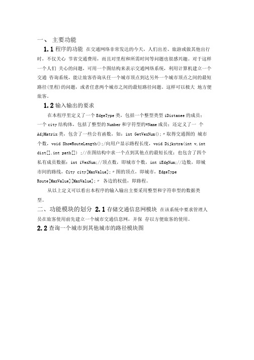
1.2输入输出的要求在本程序里定义了一个EdgeType类,包括一个整型类型iDistanee的成员;一个city结构体,包括了整型的Number和字符型的*Name成员;还定义了一个AdjMatrix类,包含了一些公有函数,如:int GetVexNum();〃取得交通图的城市个数,void ShowRouteLength();/向用户显示路程长度,void Dijkstra(int v,int dist[],int path[]) ;//在图结构中求一个点到其他点的最短长度;也包含了四个私有成员数据:int iVexNum;//顶点数,即城市个数,int iEdgNum;//边数,即城市间的路线,City city[MaxValue];〃图的顶点,即城市,EdgeTypeRoute[MaxValue][MaxValue];〃各边的权值,即路程。
从以上定义可以看出本程序的输入输出主要采用整型和字符串型的数据类型。
二、功能模块的划分2.1存储交通信息网模块在该系统中要求管理人员在旅客使用前先建立一个城市交通信息网,并保存以方便旅客的使用。
2.2查询一个城市到其他城市的路径模块图图(2)任意两个城市之间路径查询模块图2.4整个系统程序模块图图(3)整个系统查询模块图2三、主要功能的实现3.1.1城市交通咨询系统的流程图图(4)城市交通咨询系统的流程图在本系统中设置了三个模块分别为:管理员模块:这个模块包含了创建城市交通信息网,它是这个程序往下运行的前提。
- 1、下载文档前请自行甄别文档内容的完整性,平台不提供额外的编辑、内容补充、找答案等附加服务。
- 2、"仅部分预览"的文档,不可在线预览部分如存在完整性等问题,可反馈申请退款(可完整预览的文档不适用该条件!)。
- 3、如文档侵犯您的权益,请联系客服反馈,我们会尽快为您处理(人工客服工作时间:9:00-18:30)。
……………………大学算法与数据结构课程设计报告题目:交通咨询系统设计者:25045012专业班级:本网络学号:指导教师:所属系部:计算机科学与技术系2012年06月03日目录1 问题描述及要求 (1)2 需求分析 (1)3 算法思想描述 (1)4 概要设计 (4)5 详细设计 (5)6 测试数据及分析 (9)7课程设计总结 (11)8 参考资料 (11)这是我老师给我的题目我所真实上交的作品,在VC++6.0上完美运行,文档上也有截图。
对于上传分享了这作品,我想说明两点:一是我这个程序,不是绝对原创,但是所参考的那个程序是不完美的——首先界面并不友好,我已经重新设计了文字提示界面;原程序有个bug,就是在目的地和出发地重合的时候显示距离是无穷大,正确明显为0,我在老师的帮助下进行了修改算法解决了这个问题,在此我感谢我的指导老师龙老师认真负责对我进行指导,也很感谢原程序的作者为我提供程序主体和基本思路。
这个word文档的其他部分90%是自己完成的(不否认有部分是参考了别人的)。
二是若有人想借鉴本作品,希望改得体无完肤,因为程序的算法和提示语我的个人风格很浓,容易辨认,如果你的老师不巧只需浏览了一次,真的可以一眼辨认你是网上抄的。
——写给想借鉴本文档的网友交通咨询系统1 问题描述及要求设计一个交通咨询系统,能让旅客咨询从任一个城市定点到另一个城市定点之间的最短路径或最低花费或最少时间等问题。
对于不同的咨询要求、可输入城市间的路程或所需时间或所需花费。
设计要求:1. 建立交通网络网的存储结构。
2. 总体设计要画流程图。
3. 提供程序测试方案。
4. 界面友好。
2 需求分析根据要求,需要在系统中建立无向图。
系统应该有高度灵活性,可以由用户根据当前交通网络图输入初始数据,并且可以更改。
系统根据用户的输入建立无向图的结构,并通过狄克斯特拉算法和弗洛伊德算法实现要求,并提供两种功能供用户选择。
3 算法思想描述首先总体的思想步骤是:设为从到的只以4 概要设计系统应该分为三个部分,一是建立交通网络图的存储结构;二是解决单源最短路径问题;最后再实现两个城市顶点之间的最短路径问题。
1、 建立图的存储结构:无向图首先定义交通图的存储结构。
邻接矩阵是表示图形中顶点之间相邻关系的矩阵。
设G=(V ,E )是具有n 个顶点的图,则G 的邻接矩阵是具有如下定义的n 阶方阵。
A[i ,j]=⎩⎨⎧∞>∈<。
,当不满足上述条件时或或,若0);(,),(G E vj vi vj vi Wij一个图的邻接矩阵表示是唯一的。
图的邻接矩阵表示,除了需要用一个二维数组存储顶点之间相邻关系的邻接矩阵外,通常还需要使用一个具有n 个元素的一维数组来存储顶点信息,其中下标为i 的元素存储顶点vi 的信息2、 单源最短路径:狄克斯特拉算法初始化S 和D ,置空最短路径终点集,置初始的最短路径值;S[v1]=TRUE ;D[v1]=0;//S 集初始时只有源点,源点到源点的距离为0; while (S 集中顶点数<n ) {开始循环,每次求得v1到某个v 顶点的最短路径,并加v 到S 集中; S[v]=TRUE ;更新当前最短路径及距离;}3、 任意一对顶点间最短路径:弗洛伊德算法假设为从到的只以集合中的节点为中间节点的最短路径的长度。
1. 若最短路径经过点k ,则;2. 若最短路径不经过点k ,则。
因此,最短路径。
5 详细设计程序源代码如下://交通咨询系统#include<stdio.h>#include<stdlib.h>#define Num 300 //定义常量Num#define Maxint 32767enum boolean{FALSE,TRUE}; //定义布尔类型typedef char VertexType;typedef int Adjmatrix;typedef struct{VertexType vexs[Num];Adjmatrix arcs[Num][Num];}MGraph;int D1[Num],P1[Num];int D[Num][Num],P[Num][Num];void CreateMGraph(MGraph *G,int n,int e); //构建城市的无向图的声明void Dijkstra(MGraph *G,int v1,int n); //狄克斯特拉算法的声明void Floyd(MGraph *G,int n); //弗洛伊德算法的声明void main(){ MGraph *G; //定义无向图Gint n,e,v,w,k;int m=1;G=(MGraph *)malloc(sizeof(MGraph));printf("欢迎使用【交通咨询系统】!本系统约定:\n1.记一个城市为一个点,点用从1开始按顺序的编号表示,两个城市的连线为一条边;\n2.程序要求输入的文本都是按回车进行确认;\n3.程序输入输出均不带单位,单位默认为“公里”。
\n\n");printf("系统需要知道地图的结构,请输入顶点个数和边数,用“,”号隔开:\n");scanf("%d,%d",&n,&e);CreateMGraph(G,n,e);//调用CreateMGraph有向图函数while(m!=0){printf("============================================================ ===================\n");printf("请输入数字:\n");printf("0 : 退出\n");printf("1 : 求一个城市到其他所有城市的最短路径\n");printf("2 : 求任意的两个城市之间的最短路径\n");scanf("%d",&m);if(m==2){Floyd(G,n);printf("请输入起点和终点,用“,”号隔开:\n");scanf("%d,%d",&v,&w);k=P[v][w];if(k==0)printf("\n输出的结果:\n顶点%d到%d无路径!\n",v,w);else{printf("\n输出的结果:\n从顶点%d到%d的最短路径是: %d",v,w,v);while(k!=w){printf("→%d",k);k=P[k][w];}printf("→%d",w);printf("\n 路径长度: %d\n",D[v][w]);}}elseif(m==1){printf("请输入起点编号:\n");scanf("%d",&v);Dijkstra(G,v,n);}}printf("程序已结束!谢谢您的使用!\n");}void CreateMGraph(MGraph *G,int n,int e) //构建城市的无向图{int i,j,k,w;for(i=1;i<=n;i++) //以任意城市i出发为起点G->vexs[i]=(char)i;for(i=1;i<=n;i++)for(j=1;j<=n;j++) //任意城市j为终点{G->arcs[i][j]=Maxint; //距离初始化if(i==j)G->arcs[i][j]=0;}printf("\n请输入%d条边的两端点序号和长度,用“,”号隔开\n例如:1号城市到2号城市的长度为3,则输入1,2,3): \n",e);for(k=1;k<=e;k++){scanf("%d,%d,%d",&i,&j,&w);G->arcs[i][j]=w; //建立城市之间的距离G->arcs[j][i]=w;}printf("\n地图的结构建立成功!\n");}void Dijkstra(MGraph *G,int v1,int n) //狄克斯特拉算法求一个城市到任意一个城市的距离{int D2[Num],P2[Num];int v,i,w,min;enum boolean S[Num];for (v=1;v<=n;v++){S[v]=FALSE; //s[]置空D2[v]=G->arcs[v1][v]; //距离初始化if(D2[v]<Maxint) // 路径初始化P2[v]=v1;elseP2[v]=0;}P2[v1]=0;S[v1]=TRUE; //源点V1放入s中for(i=2;i<n;i++){ //循环直至所有顶点的最都求出min=Maxint; //Maxint置最小长度初值for(w=1;w<=n;w++) //选不在S中且有最小顶点w if(!S[w]&&D2[w]<min){v=w;min=D2[w];}S[v]=TRUE;for(w=1;w<=n;w++) //顶点w加入s中if(!S[w]&&(D2[v]+G->arcs[v][w]<D2[w])) //修改不在s中的顶点的距离{D2[w]=D2[v]+G->arcs[v][w];P2[w]=v;}}printf("\n输出的结果:\n");printf("路径长度路径\n"); //输出最短路径for(i=1;i<=n;i++){printf("%5d",D2[i]);printf("%10d",i); v=P2[i];while(v!=0){printf("←%d",v);v=P2[v];}printf("\n");}}void Floyd(MGraph *G,int n) //用弗洛伊德算法求任意两顶点最短距离{int i,j,k; //定义三个变量for(i=1;i<=n;i++)for(j=1;j<=n;j++){if(G->arcs[i][j]!=Maxint) //距离初始化P[i][j]=j; //路径初始化elseP[i][j]=0;D[i][j]=G->arcs[i][j];}for(k=1;k<=n;k++) //以k为源点循环求出所有顶点的最短路径{for(i=1;i<=n;i++) //i为已知最短路径的顶点for(j=1;j<=n;j++) //j为未知最短路径的顶点{ if(D[i][k]+D[k][j]<D[i][j]){D[i][j]=D[i][k]+D[k][j];P[i][j]=P[i][k];}}}}6 测试数据及分析假如某交通网络上有4个城市(序号为1,2,3,4),4个城市之中有5条道路(不同长度),交通网络图如下图所示:打开本系统,界面如图:输入4,5之后按下键盘上的回车键:根据交通网络图输入线路数据后按回车:选择1回车后,再输入城市2,求得出的结果如下:选择2后,要计算1到3的最短距离和路径,输入1,3,得到结果,并与输入3,1的输出结果作对比如下:7课程设计总结在我对作品完成了最后的调试和运行之后,紧张的一个星期的课程设计终于暂时告一段落。