BF1088-0_Application_form_MCS_Solar_PV
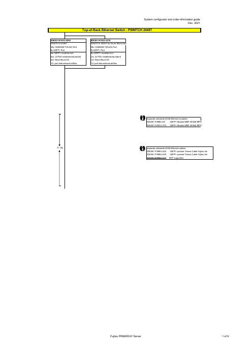
PFSWITCH 2048T 商品说明书
no power cord
T26139-Y3850-E10
T26139-Y1968-L180 T26139-Y1968-L250 T26139-Y1968-L10
T26139-Y1741-L90
T26139-Y1757-L10 T26139-Y1753-L10 T26139-Y1740-L10 T26139-Y1744-L10 T26139-Y1745-L10 T26139-Y1746-L10 T26139-Y1747-L18 T26139-Y1748-L10
Region Kits, 1x per System Region Kit Europe, Contains warranty sheet and safety instructions in German, English, French, Spanish, Italian, Polish, Russian and Welsh language
S26361-F1452-E100 S26361-F1452-E130
End of PSWITCH 2048T
CAT 6A S/STP RJ45 cables can be used for proper cabling: S26361-F3417-L602: CAT 6A, RJ45 connector, 2m S26361-F3417-L603: CAT 6A, RJ45 connector, 3m S26361-F3417-L605: CAT 6A, RJ45 connector, 5m S26361-F3417-L610: CAT 6A, RJ45 connector, 10m S26361-F3417-L615: CAT 6A, RJ45 connector, 15m
ABB电源说明书

1ABBFeaturesRated output voltage 24 V DCOutput voltage adjustable via front‑face rotary potentiometer “OUTPUT Adjust” Rated output current 2.5 A Rated output power 60 WWide range input 100‑240 V AC (85‑264 V AC, 90‑375 V DC) Typical efficiency of 89 %Low power dissipation and low heatingFree convection cooling (no forced cooling with ventilators) Ambient temperature range during operation ‑40...+70 °C Open‑circuit, overload and short‑circuit stable Integrated input fuseRedundancy unit CP‑RUD offering true redundancy, available as accessory Signalling output "DC OK" (Transistor) for output voltage OKLEDs for status indicationApprovalsA UL 508, CAN/CSA C22.2 No.14Approval refers to rated input voltage U inH UL 1310, CAN/CSA C22.2 No.223(Class 2 Power Supply)H ANSI/ISA‑12.12 (Class I, Div. 2,hazardous locations)H UL 60950, CAN/CSA C22.2 No.60950Approval refers to rated input voltage U in DGOST ECCC Approval refers to rated input voltage U inMarksa CE bC‑TickOrder dataOrder data ‑ AccessoriesApplicationThe primary switch mode power supply offers two voltage input ranges. This enables the supply with AC or DC. Furthermore it is equipped with two generous capacitors, which ensure mains buffering of at least 30 ms (at 230 V AC). That is why the devices can be used worldwide also in high fluctuating networks and battery‑powered plants.� � �� �2C D C 271 015 F 0t 06�a OUTPUT L+, L‑:terminals ‑ output b DC OK: terminal ‑signalling output c INPUT L, N, PE:terminals ‑ inputd OUTPUT OK: green LED ‑output voltage OK e OUTPUT Adjust:p otentiometer ‑adjustment of output voltage f Circuit diagram2ABBOperating modeBy means of the potentiometer …OUTPUT Adjust“ the output voltage can be adjusted within a range of 24 to 28 V DC. Thus, the power supply can be optimally adapted to the application, e.g. compensating the voltage drop caused by a long line length.The green LED …OUTPUT OK“ is lightening during operation.InstallationMountingThe switch mode power supply can be snapped on a DIN rail according to IEC/EN 60715 as shown in the accompanying picture. For that the device is set with its mounting rail slide on the upper edge of the mounting rail and locked by lifting it downwards.DemountingRemove the switch mode power supply as shown in the accompanying picture. For that the latching lever is pulled downwards by means of the screwdriver. Alternatively you can press the unlock button to release the device. Then in both cases the device can be unhinged from the mounting rail edge and removed.Mounting positionThe devices have to be mounted horizontally with the input terminals on the bottom. In order to ensure a sufficient convection, the minimum distance to other modules should not be less than 25 mm in vertical and h orizontal direction.Electrical connectionConnect the input terminals L and N. The protective earth conductor PE must be connected. Thei nstallation must be executed acc. to EN 60950, provide a suitable disconnecting device (e. g. linep rotection switch) in the supply line. The input side is protected by an internal input fuse. Rate the lines for the maximum output current (considering the short‑circuit current) or provide as eparate fuse protection. We recommend to choose the cable section as large as possible in order to minimize voltage drops. Observe the polarity. The device is overload, short‑circuit and open‑circuit proof. The secondary side of the power supply unit is electrically isolated from the input and internally notearthed (SELV) and can therefore be earthed by the user according to the needs with L+ or L‑ (PELV).3ABBConnection diagramL+, L‑Output voltage L, N Input voltageDC OK Signalling output for output voltage OK PE Protective earthWiring instructionsSafety instructions and warningsThe device must be installed by qualified persons only and in accordance with the specific nationalr egulations (e.g., VDE, etc.). The devices are maintenance‑free chassis‑mounted units.Disconnect system from supply network!Before any installation, maintenance or modification work: Disconnect the system from the supplyn etwork and protect against switching on.Before start of operation:Attention! Improper installation/operation may impair safety and cause operational difficulties ord estruction of the unit. Before operation the following must be ensured: Connect to main according to the specific national regulations.Power supply cables and unit must be sufficiently fused. A disconnecting device has to be provided for the power supply to disengage unit and supply cables from supply mains if required. The protective earth conductor must be connected to the terminal PE (Protection class I)The secondary side of the power supply unit is not earthed and can be earthed by the user according to the needs with L+ or L‑.Rate the output lines for the output current of the power supply and connect them with the correct polarity.In order to ensure sufficient air‑cooling the distance to other devices has to be considered.In operation:Do not modify the installation (primary and secondary side)! High current! Risk of electric arcs and electric shocks (danger to life)!Risk of burns: Depending on the operation conditions the enclosure can become very hot.The internal fuse is not user‑replaceable. If the internal fuse blows, most probably the device isd efective. In this case, an examination of the switch mode power supply by the manufacturer is n ecessary.Attention! High voltage! Danger to life!The power supplies contain components with high stored energy and circuits with high voltage! Do not introduce any objects into the unit, and do not open the unit. With some units of this range theo utput is capable of providing hazardous energy. Ensure that the service personnel is protected againstinadvertent contact with parts carrying energy.2C D C 272 056 F 0b 06DC OKL-2C D C 272 017 F 0207RelayR L > 700 �5 V SignalTechnical dataData at T a = 25 °C, U in= 230 V AC and rated values, unless otherwise indicatedABB 45ABB6ABB Technical diagramsOutput behavoiurI out [A]Characteristic curve of output at T a = 25 °CThe switch mode power supply CP‑E 24/2.5 is able to supply at 24 V DC output voltage andat an ambient temperature of:≤ 60 °C a continuous output current of approx. 2.5 Aat ambient temperatures of:60 °C < T a ≤70 °C the output power has to be reduced by 2.5 % per °C temperature increase.If the switch mode power supply is loaded with an output current > 2.5 A, the operating point isp assing through the U/I characteristic curve shown.Temperature behaviour2CDC27217F211Characteristic curve of temperature at rated load7ABBDimensionsin mm2C D C 272 023 F 0011CP-E 24/2.5Dimensions accessoriesin mmCP-RUDFurther DocumentationYou can find the documentation on the internet at /lowvoltage R Control Products RPower Supplies2C D C 252 188 F 0b 05As part of the on‑going product improvement, ABB reserves the right to modify the characteristics of the products described in this document. The information given is non‑contractual.For further details please contact (/contacts) the ABB company marketing these products in your country.D o c u m e n t n u m b e r : 2C D C 114 045 D 0201 (09/2011)ABBABB STOTZ-KONTAKT GmbHEppelheimer Strasse 82, 69123 Heidelberg, Germany Postfach 10 16 80, 69006 Heidelberg, GermanyInternet /lowvoltage R Control ProductsContact: /contacts R Low Voltage Products and Systems。
SC1088中文资料
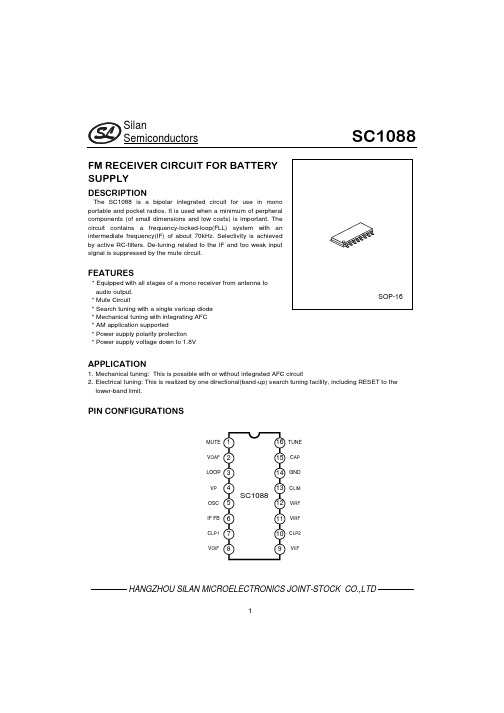
Pin No. 9 10 11 12 13 14 15
Symbol ViIF CLP2 VIRF VIRF CLIM GND CAP
16
TUNE
Description IF input to limiter amplifier Low-pass capacitor of IF limiter amplifier Radio frequency input Radio frequency input Limiter offset voltage capacitor Ground All-pass filter capacitor.input for search tuning
HANGZHOU SILAN MICROELECTRONICS JOINT-STOCK CO.,LTD
5
元器件交易网
Silan Semiconductors
HANGZHOU SILAN MICROELECTRONICS JOINT-STOCK CO.,LTD
Tamb=25°C,Vp=3V,Firf=96MHz modulated with ∆f=±22.5kHz and fm=1kHz deviation;EMF=0.3mV(e.m.f. at a
sourse impedance of 75Ω),and measurement taken in fig.3 Unless otherwise specified
元器件交易网
Silan Semiconductors
SC1088
FM RECEIVER CIRCUIT FOR BATTERY SUPPLY
DESCRIPTION
The SC1088 is a bipolar integrated circuit for use in mono portable and pocket radios. It is used when a minimum of perpheral components (of small dimensions and low costs) is important. The circuit contains a frequency-locked-loop(FLL) system with an intermediate frequency(IF) of about 70kHz. Selectivity is achieved by active RC-filters. De-tuning related to the IF and too weak input signal is suppressed by the mute circuit.
CISCO交换机路由器配置手册

CISCO交换机路由器配置手册王国栋编著……………… 目录………………交换机1、cisco 2950 交换机2、cisco 1950 交换机3、VLAN 间的通信路由器一、路由器配置1、路由器基本配置2、路由器的密码恢复3、恢复出厂设置4、备份IOS5、恢复IOS6、备份路由器配置7、静态路由的配置8、RIP路由协义配置9、IGRP路由协议配置10、EIGRP路由协议配置11、ospf路由协议基本配置12、点到点链路上的ospf13、广播链路上的ospf14、基于区域的ospf简单口今及MD5认证15、多区域的OSPF16、OSPF末节区域和完全末节区域17、OSPF命令汇总二、ACL NAT DHCP1、标准访问控制列表(Access Control Iists ) (list 列表)2、扩展访问控制列表(Access Control Iists ) (list 列表)3、命名ACL4、NAT(network address translation)网络地址翻译(1)、静态NAT配置(2)、动态NAT(3)、PAT(端口地址转换)配置5、DHCP (dynamic host configuration protocol) 动态主机配置协议三、远程接入、VPN1、HDLC (高级数据链路控制high-level data link control)2、路由器serial端口的基本配置3、PPP(1)、PPP的PAP认证(2)、PPP的CHAP认证4、帖中继(1)、帧中继基本配置(2)、点对多点帧中继(3)、|点对点帧中继上的RIP协议5、DDN(Digital Data Network 数字数据网)和数字链路6、ISDN7、ADSL Asymmetrical digital subscriber loop 非对称数字用户环路8、VPN 虚专用网络(Virtual Private Networks)交换机部分一、交换机配置图:二、环境说明:S2950-1 S2950-2 为12端口快速以太网交换机三、配置实例:1、cisco 2950 交换机//switch>enable//进入特权模式//switch #configure terminal//进入全局配置模式//switch (config)#hostname s2950-1//给交换机命名为S2950-1enable password 123456//设置密码ip address 192.168.0.1 255.255.255.0ip default-gateway 192.168.0.254ip domain-name //设置IP 、网关和域名ip name-server 200.0.0.1//设置域名服务器interface fastethernet 0/1//进入端口配置模式//s2950-1 (config-if)#speed auto//将接口速率设置成自适应(默认)//speed 100 10 auto//将接口速率设置成10/100自适应duplex full//将接口设置成全双功(默认)//duplex full falf autoend//s2950-1#copy running-config startup-config//保存配置文件valn database//从特权模式进入VLAN配置子模式//s2950-1 (vlan)#vtp server//VTP就是VLAN中继协议//设置交换机为VTP服务模式//vtp server client transparentvtp domain name-vtp-server//设置管理域的域名为name-vtp-server//创建管理域并命名end//s2950-1#configure terminal//s2950-1 (config)#interface fastethernet 0/1//s2950-1 (config-if)#switchport mode trunk//将端口fastethernet0/1设置为主干端口end//s2950-1#vlan database//s2950-1 (vlan)#//进入VLAN 配置模式valn 2 name namevlan-2//创建VLAN 2 并命名为namevlan-2//交换机默认所有未配置VLNA的交换机均为VLAN 1 //所以这里从VLAN 2 开始设置valn 3 name namevlan-3//创建VLAN 3并命名为namevlan-3valn 4 name namevlan-4valn 5 name namevlan-5exit//s2950-1#configure terminal//s2950-1 (config)#interface fastethernet 0/2//s2950-1 (config-if)#switchport mode access//设置当前端口为静态VLAN模式switchport access vlan 2//把当前端口分配给V ALN 2exit//s2950-1 (config)#interface fastethernet 0/3//s2950-1 (config-if)#switchport mode accessswitchport access vlan 3exit//s2950-1 (config)#interface fastethernet 0/4//s2950-1 (config-if)#switchport mode accessswitchport access vlan 4exit//s2950-1 (config)#interface fastethernet 0/5//s2950-1 (config-if)#switchport mode accessswitchport access vlan 5end//s2950-1#copy running-config startup-config//writeshow running-config//show vtp status//show vlan//show interface//show interface brief//show version2、cisco 1950 交换机//switch>enable//switch #configure terminal//switch (config)#hostname s2950-1enable password 123456username text1 password text2ip address 192.168.0.1 255.255.255.0ip default-gateway 192.168.0.254ip domain-name ip name-server 200.0.0.1interface fastethernet 0/1//s1950-1 (config-if)#speed auto//speed 100 10 autoduplex full//duplex full falf autoend//s1950-1#copy running-config startup-config//s1950-1#configure terminal//s1950-1 (config)#vtp server//在配置模式下设置交换机为VTP服务器//vtp server client transparent//也可以根据需要将交换机设置为VTP客户模式,或透明模式vtp domain name-vtpserver//创建VTP管理域并设置域名为name-vtpserverend//S1950VTP这块配置内容和s2950不一样//s1950-1#configure terminal//s1950-1 (config)#interface fastethernet 0/1//s1950-1 (config-if)#trunk on//设置VLAN主干端口//trunk on|off|desirable|autoEnd//trunk 的内容和S2950不一样//s1950-1#vlan database//s1950-1 (vlan)#valn 2 name namevlan-2//创建VLAN 2 并命名为namevlan-2//交换机默认所有未配置VLNA的交换机均为VLAN 1 ,//所以这里从VLAN 2 开始设置valn 3 name namevlan-3valn 4 name namevlan-4valn 5 name namevlan-5exit//s1950-1#configure terminal//s1950-1 (config)#interface fastethernet 0/2//s1950-1 (config-if)#vlan-membership static namevlan-2//划分VLAN端口//将本端口设置为namevlan-4的成员//S1950这块配置内容和s2950不一样exit//s1950-1 (config)#interface fastethernet 0/3//s1950-1 (config-if)#vlan-membership static namevlan-3exit//s1950-1 (config)#interface fastethernet 0/4//s1950-1 (config-if)#vlan-membership static namevlan-4exit//s1950-1 (config)#interface fastethernet 0/5//s1950-1 (config-if)#vlan-membership static namevlan-5end//s1950-1#copy running-config startup-configshow running-config//show vtp status//show vlan//show interface//show ip interface brief//显示所有接口的简短信息//show version3、VLAN间的通信(1)、利用三层交换机实现VLAN间的通信拓朴图:配置实例:S2950#vlan databaseS2950(vlan)#vlan 2 name namevlan-2S2950(vlan)#vlan 3 name namevlan-3S2950(vlan)#exitS2950#configure terminalS2950(config)#interface fastethernet 0/5S2950(config-if)#switchport mode accessS2950(config-if)#switchport access vlan 2S2950(config-if)#exitS2950(config)#interface fastethernet 0/6S2950(config-if)#switchport mode accessS2950(config-if)#switchport access vlan3S2950(config-if)#exitS2950(config)#ip routing//打开三层交换机的路由功能S2950(config)#interface vlan 2//将VLAN当成一个接口进行配置S2950(config-if)#no shutdownS2950(config-if)#ip address 192.168.0.1 255.255.255.0 S2950(config-if)#exitS2950(config)#interface vlan 3S2950(config-if)#no shutdownS2950(config-if)#ip address 192.168.1.1 255.255.255.0S2950(config-if)#endS2950#show ip router//由于是在同一三层交换机上,用show ip router 可以看到自动生存的路由表(2)、利用路由器实现VLAN间的通信配置拓朴图:配置实例:S2950#vlan databaseS2950(vlan)#vlan 2S2950(vlan)#vlan 3S2950(vlan)#exitS2950#configure terminalS2950(config)#interface fastehernet 0/1S2950(config-if)#switchport mode accessS2950(config-if)#switchport access vlan 2S2950(config-if)#exitS2950(config)#interface fastethernet 0/6S2950(config-if)#switchport mode accessS2950(config-if)#switchport access vlan 3S2950(config-if)#exitS2950(config)#(end)RouterA(config)#interface ethernet 0RouterA(config-if)#no shutdownRouterA(config-if)#ip address 192.168.0.1 255.255.255.0 RouterA(config-if)#exitRouterA(config)#interface ethernet 1RouterA(config-if)#no shutdownRouterA(config-if)#ip address 192.168.1.1 255.255.255.0 RouterA(config-if)#endRouterA#show ip route//可以看到由路器自动生成的两条路由表路由器部分一、路由器配置1、路由器基本配置(1)路由器基本的配置拓扑图:(2)、环境说明:Cisco 1605路由器(3)、配置实例://Router>enable//Router#configure terminal//Router(config)#enable password text1//enable secret texe2hostname R1no ip domain lookup//不用DNS 解析主机IPinterface fastethernet 0/1//R1605-1(config-if)#ip address 192.168.0.2 255.255.255.0no shutdownexit//R1605-1 (config)#interface fastethernet 0/2//R1605-1 (config-if)#ip address 192.168.0.2 255.255.255.0no shutdownexit//R1605-1 (config)#ip route 0.0.0.0 0.0.0.0 192.168.1.2//配置默认路由//no ip route 0.0.0.0 0.0.0.0 192.168.1.2ip routing//起动路由功能//R1605-1(config)#line vty 0 4//VTY是路由器给远程登陆准备的虚拟端口//0 4表示可以同时打开5个会话//line vty 0 4是进入VTY端口(也就是同时充许5个会话登陆),对VTY端口//进行配置//R1605-1(config-line)#password 123456//设置telnet登陆时使用的密码//no password 这样就不能从telnet登陆了.(当你no password 取消掉了密码,//telnet会拒绝连接,这样就关闭了telnet)//要想明确禁止从telnet登陆最好使用ACL关闭23端口login//要求输入密码方能从telnet远程登陆,//no login 不使用密码就可以从telnet登陆end//R1605-1#write//copy running-config startup-config ,保存配置end//R1605-1#Show running-config//show version//show interface//show ip interface brief//显示所有接口的简短信息//show ip route//traceroute ip 192.168.3.1//show ip arp//show ip rip database//show runing-configexit2、路由器的密码恢复(1)、密码恢复的基本原理对CISCO的网络设备进行密码恢复的主要武器是配置注册码。
Edgecore AS4610-54T 1GbE Data Center和企业交换机裸机硬件产品概述

Design Contributed to Open Compute Project4842XO 128 GbpsPhysical and EnvironmentalDimensions (HxWxD): 4.5 x 44 x 35 cm (1.7 x 17.3 x 16.1”) 1 RU WeightAS4610-54T: 5.38 kg (11.86 lb) AS4610-54T (B): 5.53 kg (12.19 lb) Fans:AS4610-54T: PSU fansAS4610-54T (B): 2 fans: Back-to-front direction Operating Temperature: 0°C to 45°C Storage Temperature: -40°C to 70°COperating Humidity: 5% to 95% non-condensingSoftwareSwitch is loaded with Open Network Install Environment (ONIE)software installerCompatible with the following NOS options:PicOS r2.6.2 and later version from Pica8 IncCumulus Linux r2.5.4 and later version from Cumulus Networks SnapRoute FlexSwitch softwarePowerPSUs: 2 redundant, load-sharing, hot-swappable AC Input Voltage: 90 to 264 VAC at 50-60 Hz.Input Current: Max 13 A@100/120 VAC, 3 A@200/240 VACTypical Power consumption (under line-rate, 48 x 1 GbE Cat 6,4 x 10GBASE-SR test condition): 117 WRegulatoryEMI:CE Mark (EN55022 Class A) FCC Part 15 Class A VCCI Class A BSMI (CNS13438)Australia RCM (AS4610-54T-B only) Vietnam MIC (AS4610-54T-B only) Korea (AS4610-54T-B only) Brazil (AS4610-54T-B only) Environmental:Temperature: IEC 68-2-14 Shock: IEC 68-2-29Vibration: IEC 68-2-36, IEC 68-2-6 Drop: ISTA 2A RoHS-6 Compliant Safety:UL (CSA 22.2 No 60950-1 & UL 60950-1) CB (IEC/EN60950-1)Mexico NOM (AS4610-54T-B only)CCC (AS4610-54P/AS4610-54T-B only) Argentina S-Mark (AS4610-54T-B only) BSMI (CNS14336)Country of Origin: Taiwan (TAA Compliant)WarrantyPlease check for the warranty terms in your country.PortsSwitch Ports:48 x RJ-45 100/1000BASE-T ports4 x 10G SFP+ ports supporting 10G or 1G2 x 20G QSFP+ Stacking Port (requires NOS to support hardware stacking feature)Management Ports: AS4610-54T Front-to-Back SKUs:1 x Micro-USB serial console1 x RJ-45 100/1000BASE-T management port 1 x USB Type A storage portManagement Ports: AS4610-54T-B Back-to-Front SKU:1 x RJ-45 serial console1 x RJ-45 100/1000BASE-T management port 1 x Micro-USB to USB Type A storage portKey ComponentsSwitch Silicon: Broadcom BCM56340 Helix4 CPU: Dual-core ARM Cortex A9 1GHz Memory: 2 GB DDR3 SDRAM ECCFlash: 8 MB SPI Flash, 8 GB NAND FlashPerformanceWire Speed Forwarding: L2 and L3 Switching Capacity: 128 Gbps Forwarding Rate: 131 Mpps MAC Addresses: up to 96K VLAN IDs: 4KJumbo Frames: Up to 12 KBL3 Entry: IPv4/IPv6 96 k/48 k Unicast, 48 k/24 k MulticastPacket Buffer Size: 4 MB shared buffer poolSupported Optics and CablesGE RJ-45 Ports: Cat 5/5e/6 up to 100 m SFP+ Ports:10GBASE-CR DAC; 0.5 m to 7 m10GBASE-SRL/SR; up to 100/300 m over OM3 MMF 10GBASE-LR; up to 10 km over SMF1000BASE-SX, 1000BASE-LX, 100/1000BASE-T QSFP Port on Optional Module:40GBASE-CR4 DAC; 0.5 m to 7 m40GBASE-SR4; up to 100 m over OM3 MMF, 150 m over OM4 MMF40GBASE-SR4 to 4x10GBASE-SR; 100 m over OM3, 150 m OM440GBASE-LR4; up to 10 km over SMFLEDsGE RJ-45 SFP+ Port LEDs: Link Speed, Link Status, Activity 10G SFP+ Port LEDs: Link Speed, Link Status, Activity Ethernet Management Port LED: Link Status, ActivitySystem LEDs: PRI, PSU1, PSU2, STK1, STK2, FANEdgecore Networks Corporation serves customers and partners worldwide. Additional information can be found at . Edgecore Networks Corporation is a subsidiary of Accton Technology Corporation, the leading network ODM company.The Edgecore Data Center switches are developed and manufactured by Accton.To purchase Edgecore Networks solutions, please contact your Edgecore Networks Corporation representatives at +886 3 563 8888 (HQ) or +1 (949)-336-6801 or authorized resellers.© Copyright 2017 Edgecore Networks Corporation. The information contained herein is subject to change without notice. This document is for informational purposes only and does not set forth any warranty, expressed or implied, concerning any equipment, equipment feature, or service offered by Edgecore Networks Corporation. Edgecore Networks Corporation shall not be liable for technical or editorial errors oromissions contained herein.。
赛门铁克产品中文知识库文档列表

1. 赛门铁克产品中文知识库文档列表 (1)2. Symantec Endpoint Protection (SEP) 简体中文文档汇总(持续更新) (2)3. Symantec Endpoint Protection 11.0 主要文章 (8)4. NetBackup (NBU) 简体中文文档汇总(持续更新) (12)5. Backup Exec for Windows Servers (BEWS) 简体中文文档汇总(持续更新) (20)6. Backup Exec System Recovery (BESR) 简体中文文档汇总(持续更新) (30)7. Symantec Brightmail Gateway (SBG) 简体中文文档汇总(增加中) (34)8. Symantec Information Foundation 产品简体中文文档归总(持续更新) (35)9. Cluster Server (VCS) 简体中文文档汇总(持续更新) (38)10. Enterprise Vault (EV) 简体中文文档汇总(持续更新) (39)11. Storage Foundation (SF) 简体中文文档汇总(持续更新) (41)12. Volume Manager(VxVM)简体中文文档汇总(持续更新) (44)13. Volume Replicator (VVR) 简体中文文档汇总(持续更新) (45)1.赛门铁克产品中文知识库文档列表service1.symantec./SUPPORT/INTER/ent-securitysimplifiedchinesekb.nsf/cn_docid/本文档翻译自英文文档。
原英文文档可能在本翻译版发布后进行过修改更新。
赛门铁克对本翻译文档的准确度不做保证。
情形按照产品分类,将现有中文知识库文档汇总,以方便各位查阅。
解释Security (安全产品)•Symantec Endpoint Protection (SEP)•Symantec Brightmail Gateway (SBG)•Symantec Mail Security for SMTP (SMS)Availability (存储产品)•Symantec Backup Exec (BEWS)•Symantec Backup Exec System Recovery (BESR)•Symantec Cluster Server (VCS)•Symantec Enterprise Vault (EV)•Symantec NetBackup (NBU)•Storage Foundation (SF)•Symantec Volume Manager (VxVM)•Symantec Volume Replicator (VVR)•文档号:最近更新: 2009-12-02Date Created: 2009-10-15产品: All Products2.Symantec Endpoint Protection (SEP) 简体中文文档汇总(持续更新)本文档翻译自英文文档。
FUJITSU Software Systemwalker软件配置管理器V15说明书

April 2013 Fujitsu Limited
Copyright 2013 FUJITSU
Table of Contents
Product Overview Product Information
Reduced system construction time and human error
Automatic setting of software according to
pre-designed information
4
Copyright 2013 FUJITSU LIMITED
Features
7
Copyright 2013 FUJITSU LIMITED
Functions (2)
Internet
Tenant user
Tenant administrator
Infrastructure administrator
Patch and configuration information management
Configuration management of software in data centers relevant to system operation
management, reducing the burden on system administrators
Discovery/Software Configuration Management
automatically, such as physical server information or rack information
N-TRON 708FX2工业互联网交换机说明说明书

708FX2 Industrial Ethernet SwitchN-Tron Networking SeriesThe N-TRON ® 708FX2 Industrial Ethernet Switch combines outstanding performance and ease of use. The fully managed switch is ideally suited for connecting Ethernet-enabled industrial and/or security equipment.PRODUCT FEATURES• Six 10/100BaseTX RJ-45 Ports• Two 100BaseFX Fiber ports, ST or SC style • -40o C to 85o C Operating temperature• ESD and Surge Protection Diodes on all Ports • Auto Sensing 10/100BaseTX, Duplex, and MDIX • Store-and-Forward Technology • Rugged DIN-Rail Enclosure• Redundant Power Inputs (10-30 VDC) • Con fi gurable Alarm Contact• Con fi gurable Bi-Color Fault Status LEDFully Managed Features:• Full SNMP and Web Browser Management• Detailed Ring Map and Fault Location Charting • N-Ring ™ Technology with ~30ms Healing • N-View ™ OPC Monitoring • Plug-and-Play IGMP Support• 802.1Q tag VLAN and Port VLAN • 802.1p QoS and Port QoS • EtherNet/IP ™ CIP Messaging• LLDP (Link Layer Discovery Protocol) • Trunking • Mirroring• 802.1d, 802.1w, 802.1D RSTP• DHCP Server, Option 82 relay, Option 61, IP Fallback• Port Security—MAC Address BasedManagement FeaturesThe 708FX2offers several management functions that can be easily con fi gured using a web browser.IGMP Snooping - Internet Group Management Protocol is a feature that allows the 708FX2switch to forward and filter multicast traffic intelligently.VLAN - Virtual Local Area Network allows you to segment the switch in order to create two or more separate local area network domains.QoS - Quality of Service provides prioritization of network traf fi c in order to provide better network service. The primary goal of QoS is to improve the latency of prioritized Ethernet packets required for ring management, real-time, and other interactive applications.Trunking - Trunking (link aggregation) enables multiple physical ports to be linked together and function as one uplink to another N-TRON trunking capable switch con fi gured in the same manner, thereby increasing the bandwidth between switches. This con fi guration can provide increased bandwidth and redundancy to applications requiring high levels of fault tolerant operation.Port Mirroring - This function allows the traf fi c on one port to be duplicated and sent to a designated mirror port. Port mirroring can be used to monitor Ethernet traf fi c on the designated source port using the assigned mirror port.HE INDUSTRIAL NETWORK COMPANYRapid Spanning TreeThis function allows the switch to be con fi gured in a ring or mesh topology, and provides support for redundant path communications with high-speed (rapid) healing.Remote Monitoring OptionsFor ease of configuration and monitoring, the 708FX2 offers web browser management and N-View OLE for Process Control (OPC) server software. The N-TRON N-View software can be combined with popular HMI software packages to add network traf fi c monitoring, trending, and alarming to any application using N-TRON switches. In addition SNMP is available for switch link and status monitoring. The Alarm Contact and Status LED can be con fi gured to respond to power failure on power input 1 or input 2, N-Ring Broken, Partial Break High, Partial Break Low, or if multiple ring managers are detected.N-Ring TechnologyThe switch's ring manager, using N-TRON's N-Ring technology, offers expanded ring size capacity, detailed fault diagnostics, and a standard healing time of ~30ms. The 708FX2 ring manager periodically checks the health of the ring via packets. If the ring manager stops receiving these health check packets, it converts the Ring to a linear bus topology within ~30ms. When all switches in the ring are N-TRON fully managed switches, a detailed ring map and fault location chart will also be provided on the ring manager’s web browser and OPC server to identfy the health status of the ring. N-Link allows the linking of two N-Rings. Up to 250 fully managed N-TRON switches can participate in N-Ring topologies.Industrial Packaging and Speci fi cationsThe 708FX2 is designed to operate in industrial environments. It is housed in a rugged steel DIN-Rail enclosure. It has extended industrial specifications and features to meet or exceed the operating parameters of the connected equipment. These include extended temperature ratings, extended shock and vibrations specs, redundant power inputs, and high MTBF (greater than 2M hours).Ease of UseThe 10/100BaseTX ports are auto sensing and auto configuring. Each copper port is automatically negotiated for maximum speed and performance by default, but can also be hard coded using the user interface. A high-speed processor allows wire speed capability on all 100BaseTX ports simultaneously.708FX2708FX2 Speci fi cationsSwitch PropertiesNumber of MAC Addresses: 8000Aging Time : Programmable Latency Typical: 2.9 μsSwitching Method : Store-and-Forward PhysicalHeight: 2.3" (5.8cm)Width:6" (15.3cm)Depth: 3.8" (9.6cm)Weight (max): 1.7 lbs (0.75kg)DIN-Rail Mount:35mmElectricalRedundant Input Voltage: 10-30 VDC Input Current (max): 330mA max @ 24VDC BTU/hr: 27 @ 24VDC N-TRON Power Supply: NTPS-24-1.3 (1.3 A @ 24V)EnvironmentalOperating Temperature: -40o C to 85o C Storage Temperature: -40o C to 85o C Operating Humidity: 5% to 95% (Non Condensing)Operating Altitude: 0 to 10,000 ft.Shock and Vibration (bulkhead mounted)Shock: 200g @10ms Vibration/Seismic: 50g, 5-200Hz, Triaxial Reliability MTBF: >2 Million Hours Network Media 10BaseT: >Cat3 Cable 100BaseTX: >Cat5 Cable 100BaseFX Multimode:50-62.5/125μm 100BaseFXE Singlemode: 7-10/125μmConnectors10/100BaseTX:Six (6) RJ-45 Copper Ports 100BaseFX: Two (2) SC or ST Fiber Duplex PortsRecommended Wiring ClearanceFront : 4" (10.16cm)Side : 1" (2.54cm)Regulatory ApprovalsFCC/CE (CFR 47, Part 15, Subpart B, Class A)EN 55011ICES-003- Class AEN61000-4-2/3/4/5/6/8/11, EN61000-6-2/4UL /cUL: Class I, Div 2, Groups A, B, C, D and T4A ANSI/ISA 12.12.01-2007ATEX II 3 G Ex nC (DEMKO 03 ATEX 0316686U)ABS Type Approval for Shipboard Applications DNV Type Approval Certi fi cation EN50155 for Railway Applications GOST-R Certi fi ed RoHS CompliantDesigned to comply with:IEEE 1613 for Electric Utility Substations NEMA TS1/TS2 for Traf fi c ControlTHE INDUSTRIAL NETWORK COMPANYFiber Transceiver CharacteristicsFiber Length 2km*15km**40km**80km**TX Power Min -19dBm -15dBm -5dBm -5dBm RX Sensitivity Max -31dBm -31dBm -34dBm -34dBm Wavelength1310nm1310nm1310nm1550nm* Multimode Fiber Optic Cable ** Singlemode Fiber Optic CableTHE INDUSTRIAL NETWORKCOMPANYTHE INDUSTRIAL NETWORK COMPANYw w w.r e d l i o n.n e tConnect. Monitor. Control.Americas *****************Asia-Pacific ****************EuropeMiddle East Africa******************+1 (717) 767-6511ADLD0292 080116 © 2016 Red Lion Controls, Inc. All rights reserved. Red Lion, the Red Lion logo, N-Tron and Sixnet are registered trademarks of Red Lion Controls, Inc. All other company and product names are trademarks of their respective owners.As the global experts in c ommunic ation, monitoring and c ontrol for industrial automation and networking, Red Lion has been delivering innovative solutions for over forty years. Our automation, Ethernet and cellular M2M technology enables companies worldwide to gain real-time data visibility that drives produc tivity. Produc t brands inc lude Red Lion, N-Tron and Sixnet. With headquarters in York, Pennsylvania, the company has offic es ac ross the Americ as, Asia-Pac ific and Europe. Red Lion is part of Spec tris plc , the produc tivity-enhanc ing instrumentation and controls company. For more information, please visit .。