Calculations of giant magnetoelectric effect in multiferroic
Giant magnetic-field-induced strain
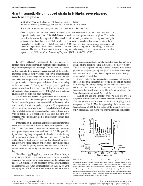
Giant magnetic-field-induced strain in NiMnGa seven-layered martensitic phaseA.Sozinov,a)A.A.Likhachev,nska,and K.UllakkoHelsinki University of Technology,P.O.Box6200,FIN-02015HUT,Finland͑Received13November2001;accepted for publication4January2002͒Giant magnetic-field-induced strain of about9.5%was observed at ambient temperature in a magneticfield of less than1T in NiMnGa orthorhombic seven-layered martensitic phase.The strain proved to be caused by magnetic-field-controlled twin boundary motion.According to an analysis of x-ray diffraction data,the crystal structure of this phase is nearly orthorhombic,having lattice parameters aϭ0.619nm,bϭ0.580nm,and cϭ0.553nm͑in cubic parent phase coordinates͒at ambient temperature.Seven-layer shuffling-type modulation along the(110)͓11¯0͔p system was recorded.The results of mechanical tests and magnetic anisotropy property measurements are also reported.©2002American Institute of Physics.͓DOI:10.1063/1.1458075͔In1996Ullakko1,2suggested the mechanism of magnetic-field-induced strain in magnetic shape memory al-loys with large magnetic anisotropy.The mechanism is based on the magnetic-field-induced rearrangement of the crystal-lographic domains͑twin variants͒that lower magnetization energy.It can provide large strain similar to a stress-induced one.Magnetic shape memory materials are expected to have a high potential in the design of a different kind of actuating devices and sensors.1,2During the few past years,significant progress based on this general idea of designing a new class of magnetic shape memory alloys͑MSMAs͒and a detailed investigation of them has been achieved.3–17As of now,the largest magnetostrain effects were at-tained in Ni–Mn–Ga ferromagnetic shape memory alloys. Several research groups have succeeded in the observation and investigation of a superlarge͑up to6%͒magnetostrain effect in some nonstoichiometric Ni2MnGa-based alloys. The crystal structure of the martensitic phase of these alloys was identified as a tetragonal one that also hasfive-layer shuffling type modulation and a tetragonality aspect ratio c/aϽ1.16,18Depending on the chemical composition and temperature there are also two other kinds of martensitic phase in Ni–Mn–Ga that have orthorhombic seven-layered and tetragonal nonlayered crystal structures with c/aϾ1.18,19The possibil-ity of observing large magneticfield-induced strain in any other martensitic phase was the main purpose of our last study.Here wefirst briefly report on the observation of su-perlarge9.5%strain effect in orthorhombic martensitic phase in Ni–Mn–Ga.It greatly exceeds the best result of6%ob-tained earlier in the tetragonalfive-layered phase of this al-loy.The alloy Ni48.8Mn29.7Ga21.5was prepared by melting in an induction furnace in argon atmosphere.A single crystal specimen was cast in an alumina crucible and solidified at a rate of0.5mm/min in the Bridgman crystal growth furnace at AdaptaMat Ltd.After homogenization at1253K for20h and aging at1073K for30h the alloy was cooled in air to room temperature.Single-crystal samples were then cut by a spark cutting machine with dimensions of4ϫ4ϫ6mm3. The faces of the prismatic single-crystal samples were nearly parallel to the͓100͔,͓010͔,and͓001͔directions of the high-temperature cubic phase.The samples were also wet pol-ished and electropolished.Figure1shows the temperature dependence of the low-field ac magnetic susceptibility of the alloy during heating and cooling.The abrupt change in the value of the suscepti-bility at367–369K is attributed to paramagnetic–ferromagnetic transformation of the L21cubic phase.The Curie temperature is about T Cϭ368K.During the cooling–heating cycle we also observed a sequence of martensitic and intermartensitic transformations. The martensitic transformation starts at337K(M s)and is completed at333K(M f)during cooling.At lower tempera-tures,starting at245K,the value of the magnetic suscepti-bility increased,indicating the intermartensitic transforma-a͒Electronic mail:asozinov@cc.hut.fiFIG.1.Temperature dependence of low-field ac magnetic susceptibilitymeasured during cooling͑solid line͒and heating͑dashed line͒of theNi48.8Mn29.7Ga21.5alloy.Arrows mark phase transformations.C:ferromag-netic cubic phase,Or:orthorhombic seven-layered phase,T:tetragonal non-modulated phase.The inset shows the scattering intensity distribution inreciprocal space between͑400͒and͑620͒nodes in the orthorhombic phaseof the Ni48.8Mn29.7Ga21.5alloy.Arrows mark additional peaks connectedwith seven-layered modulation of the lattice.APPLIED PHYSICS LETTERS VOLUME80,NUMBER1011MARCH200217460003-6951/2002/80(10)/1746/3/$19.00©2002American Institute of Physics Downloaded 19 Jun 2003 to 129.10.128.130. Redistribution subject to AIP license or copyright, see /aplo/aplcr.jsption.During heating both structure transformations occur in reverse order and show some temperature hysteresis.In par-ticular,the reverse intermartensitic transformation takes place during heating at 306–316K.So reverse martensitic transformation from the orthorhombic to the cubic parent phase upon heating takes place between A s ϭ338K and A f ϭ342K.By x-ray studies made with the Philips X’Pert diffracto-meter it was found that the crystal structure of the first high temperature martensitic phase is nearly orthorhombic and has lattice parameters of a ϭ0.619nm,b ϭ0.580nm,and c ϭ0.553nm ͑in coordinates related to the high temperature parent cubic phase ͒at ambient temperature.Seven-layermodulation along the (110)͓11¯0͔p system was observed.The insert in Fig.1shows the scattering intensity distribution in reciprocal space between ͑400͒and ͑620͒nodes recorded by a Q -type scan.There are six approximately equally spaced additional peaks.This kind of martensitic phase is known for nonstoichiometric Ni 2MnGa alloys.18,19We also found that the crystal structure of the second martensite is tetragonal with lattice parameters of a ϭb ϭ0.547nm,and c ϭ0.660nm (c /a ϭ1.207)at 200K and a ϭb ϭ0.551nm and c ϭ0.654nm (c /a ϭ1.187)at ambient temperature.Since the magnetic and the mechanical properties of non-modulated tetragonal martensite phase have recently been studied,16our attention was attracted to the orthorhombic seven-layered martensite.Usually,after a martensitic phase transition the multiple variants of martensite form within a single crystal of the parent high-temperature phase.Afterwards,that multivariant state can be transformed into a nearly single variant of mar-tensitic phase by appropriate mechanical treatment.In this way nearly single-variant samples of orthorhombic phase were prepared.The magnetic properties were determined for single-variant samples from the magnetization curves M (H )re-corded along the ͓100͔,͓010͔,and ͓001͔directions.The samples were constrained by epoxy to prevent a magneti-cally field-induced redistribution of martensite variants dur-ing the measurements.The results of the magnetic measure-ments are shown in Fig.2.The magnetization curves indicatethat the shortest axis ͑c axis ͒is the axis of easiest magneti-zation,the longest ͑a axis ͒is the axis of hard magnetization,and the b axis is the intermediate one.Unlike for a single uniaxial magnetic anisotropy constant of tetragonal phase one needs two magnetic anisotropy parameters to character-ize the orthorhombic crystal structure.The values of mag-netic anisotropy constants K b ϭ0.7ϫ105J/m 3and K a ϭ1.6ϫ105J/m 3were calculated from the magnetization data ͑Fig.2͒as the area cross section between the easiest curve ͑c axis ͒and the two others ͑b and a directions ͒.Figure 3shows the stress–strain curve obtained during compression along the ͓100͔direction ͑parallel to the longest a axis of the orthorhombic single crystal ͒.The maximal twinning strain obtained is consistent with the crystal lattice aspect ratio estimate of ⑀0ϭ(1Ϫc /a )ϭ10.66%found from x-ray diffraction studies.It was confirmed that the final crys-tallographic structure of the sample is the same orthorhombicone but transformed by twinning ͓(101)͓101¯͔system ͔from one single crystalline variant to another with the shortest c axis parallel to the direction of compression instead of to the longest a axis before the testing.The mechanical test reveals that the uniaxial compres-sive stress tw is approximately as low tw ϭ2MPa as was found before 10,12,13,16for the five-layered tetragonal phase.This is very important because the low twinning stress and high energy of magnetic anisotropy are key to obtaining a large magnetic field controlled strain response ⑀MSM ͑the MSM effect ͒through the mechanism of twin boundary motion.12,13More exactly,it is only possible in ferromagnetic shape memory alloys that satisfy the simple criterion,17K Ͼ⑀0tw .The magnetic anisotropy energy density K which is exactly equal to the magnetic driving force applied to the twin boundary 13,17must always exceed or be the same order as the mechanical driving force ⑀0tw needed to produce twinning.Strain response ⑀MSM for similar systems is expected to be practically equal to the maximal strain ⑀0ϭ(1Ϫc /a )al-lowed by twinning crystallography.In the case of the ortho-rhombic phase studied the K a value of 1.6ϫ105J/m 3is of the same order but a little less compared to ⑀0tw Ϸ2.0FIG.2.Magnetization curves measured along different axes of orthorhom-bic seven-layered phase ͑the single-variant constrained state ͒in the Ni 48.8Mn 29.7Ga 21.5alloy at 300K.FIG.3.Stress–strain curve for compression of a single-variant sample of the Ni 48.8Mn 29.7Ga 21.5alloy along the ͓100͔direction at 300K.The change in microstructure is shown schematically in the inset.Downloaded 19 Jun 2003 to 129.10.128.130. Redistribution subject to AIP license or copyright, see /aplo/aplcr.jspϫ105J/m 3.So,the large ⑀MSM value,which is a little lower than ⑀0ϭ10.66%,is expected for the orthorhombic phase.Figure 4confirms this prediction and shows the results of the field-induced strain measurements of the alloy at am-bient temperature.The magnetic field was applied parallel to the a axis.The maximal strain achieved in the first cycle at the field of 1.05T is ⑀MSM ϭ9.5%.In agreement with our earlier explanation this value is lower than the crystallo-graphic limit ⑀0ϭ(1Ϫc /a )ϭ10.66%expected for complete transformation between two single variants.As confirmed by optical observation and x-ray diffraction studies,the transfor-mation to the second variant with favorable c -axis orienta-tion along the field is not complete.There are residual twin bands in the sample.The authors would like to acknowledge funding by theNational Technology Agency of Finland ͑Tekes ͒as well as by their industrial research partners ͑Nokia Research Centre,Outokumpu Research Oy,Metso Oyj,and AdaptaMat Ltd.͒.The authors are grateful to Tor Meinander of the Technical Research Centre of Finland ͑VTT ͒for his help with magnetic measurements,to Sanni Mustala for energy-dispersive analy-sis measurements,and to Olavi Mattila of AdaptaMat Ltd.for single-crystal preparation.1K.Ullakko,J.Mater.Eng.Perform.5,405͑1996͒.2K.Ullakko,Proc.SPIE 2779,505͑1996͒.3K.Ullakko,J.K.Huang,C.Kantner,R.C.O’Handley,and V .V .Kokorin,Appl.Phys.Lett.69,1966͑1996͒.4K.Ullakko,J.K.Huang,V .V .Kokorin,and R.C.O’Handley,Scr.Mater.36,1133͑1997͒.5R.D.James and M.Wuttig,Philos.Mag.A 77,1273͑1998͒.6R.C.O’Handley,J.Appl.Phys.83,3263͑1998͒.7R.Tickle,R.D.James,T.Shield,M.Wuttig,and V .V .Kokorin,IEEE Trans.Magn.35,4301͑1998͒.8R.D.James,R.Tickle,and M.Wuttig,Mater.Sci.Eng.,A 273–275,320͑1999͒.9R.C.O’Handley,S.J.Murrey,M.Marioni,H.Nembach,and S.M.Allen,J.Appl.Phys.87,4712͑2000͒.10S.J.Murrey,M.Marioni,S.M.Allen,and R.C.O’Handley,Appl.Phys.Lett.77,886͑2000͒.11T.Kakeshita,T.Takeuchi,T.Fukuda,M.Tsujiguchi,T.Saburi,R.Oshima,and S.Muto,Appl.Phys.Lett.77,1502͑2000͒.12A.A.Likhachev and K.Ullakko,Eur.Phys.J.B 14,263͑2000͒.13A.A.Likhachev and K.Ullakko,Phys.Lett.A 275,142͑2000͒.14A.Sozinov,P.Yakovenko,and K.Ullakko,Mater.Sci.Forum 373–376,35͑2001͒.15O.Heczko,A.Sozinov,and K.Ullakko,IEEE Trans.Magn.36,3266͑2001͒.16A.Sozinov,A.A.Likhachev,and K.Ullakko,Proc.SPIE 4333,189͑2001͒.17A.A.Likhachev,A.Sozinov,and K.Ullakko,Proc.SPIE 4333,197͑2001͒.18V .V .Martynov and V .V .Kokorin,J.Phys.III 2,739͑1992͒.19J.Pons,V .A.Chernenko,R.Santamarta,and E.Cesari,Acta Mater.48,3027͑2000͒.FIG.4.Field-induced strain of a single-variant sample of orthorhombic seven-layered phase in the Ni 48.8Mn 29.7Ga 21.5alloy at 300K measured per-pendicular to the magnetic field applied along the ͓100͔direction.Downloaded 19 Jun 2003 to 129.10.128.130. Redistribution subject to AIP license or copyright, see /aplo/aplcr.jsp。
翻译 1

Mg-Al-Zn合金组织的晶粒尺在摩擦搅拌的依赖性弱搅拌处理的Y.N.王,a,b C.I.张,a C.J.李,a H.K.林a,c和黄祚芊a,*a材料科学与工程学院;纳米科学中心和纳米技术,国立中山大学圣大学,高雄804,台湾,中华民国b材料科学与工程学院,大连理工大学,大连116024,中国研究所c工研院南,工业技术研究院,台南县734,台湾,中华民国收到2006年4月25日;经修订的2006年5月18日;接受二零零六年六月七日可在网上二零零六年七月五日摘要在Mg-Zn-Al系合金热挤压加工通常表现出较强的粒度屈服应力的依赖。
然而,相同的摩擦搅拌处理的Mg-Zn-Al系合金的样品表现出弱得多的晶粒尺寸的依赖。
高施密特因子摩擦搅拌处理的样品在0.3左右,负责在的Hall-Petch关系的低参数。
关键词:镁合金;搅拌摩擦加工;纹理;晶粒尺寸的依赖镁合金已经吸引了运输车辆制造越来越大的兴趣,因为它们可以提供一个相当大的重量减少的结构。
然而,他们的延展性较差,由于在室温下的六边形结构可滑移系的数量有限,可能会限制其广泛应用。
另一方面,在镁合金的晶粒尺寸强化效率比以Al和其它合金高得多[1],这意味着晶粒细化镁合金是更有利。
大量的研究集中在镁合金的微结构上的修改已经进行,以提高和控制的机械性能[2-12]。
在镁合金中,存在基础和非基础滑移系之间的临界剪切应力(CROSS)有很大差异[13],这引起了严重的各向异性的机械性能。
其结果是,当变形镁合金具有强的晶体学织构在其微观结构,它们的机械性能显著由质地除了晶粒尺寸的影响[4-7,12,14]。
最近,研究搅拌摩擦加工(FSP)已经证明,有效的微观组织均匀化和细化可在镁基合金可以实现为严重的塑性变形和动态再结晶的结果。
已经发现该纹理具有强烈的不均匀分布沿着焊接工具的销柱表面基面的积累也带出,在搅拌区[8,15]。
有大量的报道[6,16-18]对晶粒尺寸和镁合金的基础上的Hall-Petch关系机械性能的关系之间的相关性。
翻译

土力学是土体运动和平衡的一门学科。
土是地表较高层的风化物,地表上未风化的物质称岩石,而岩石力学是专门研究这种物质的。
一般来讲,土和岩石是有着区别的,在土里能用铁锹甚至用手挖个壕沟;岩石则不行,它必须得用凿子、锤子、钻孔机才能使其破碎,岩石在阳光、雨、风长期风化作用下退变成石头。
破碎的岩石可通过岩石裂缝中水的结冰融化来增强性能,而这种表面不光滑的山里的石头在河里受地心引力作用和水一起顺流而下,石头在内摩擦作用下逐渐变小,最终变成细粒物质、砂砾、砂子甚至是淤泥,它们在流动的河流中,粗糙物质能快速沉积,细粒物质则要经过较长时间沉积,因此我们在河床高处看到砂砾,河床低处看到砂和淤泥。
荷兰位于莱茵河和默兹河的较低河段,这里一般都是砂和粘土这些物质,它们早在三角洲沉积,这种沉积作用在许多地方都存在像尼罗河、印度和中国河流的三角洲,在荷兰通过建堤坝防洪,这种沉积作用不再发生。
陆地的形成过程因而终止,但由于结构的不断运动引起塌落。
如果政府置之不理,这种现象仍会发生。
人类在陆地生存,建造了各种各样的构筑物,房子、公路、桥梁等等。
岩土工程师必须去探测土的活动。
现在有许多备受关注的问题:土重和交通道路影响下公路和铁路附近的移民问题,地球结构处在安全边缘,作用在隧道、水闸上的地表压力。
对于这些问题土力学提供了解决方法。
在20世纪初期土力学已经形成。
在许多国家发生的山崩、建筑物的倒塌导致分析土的活动已经势在必行。
在1918年在荷兰Weesp 附近发生的铁路路基的滑坡导致由政府成立的专门委员会在土力学领域进行了第一次有计划的投资。
就在那时土力学的许多原理众所周知,但它们和工程实况结合的还不够好。
对土力学做出首要贡献的是库伦,他发表了一篇关于土的重要论文,在1857年发表了关于土的压力状态的论文。
在1856年达西出版了他著名的关于土的渗透性的作品,为第戎城解决了水供应的问题。
由于牛顿、柯西、纳维的作品,包括静力学、物质强度的力学原理在19世纪也众所周知,所有的原理和规律的结合直到20世纪,有人提到投资Weesp附近发生的灾难的委员会得出结论,由于持续降雨、铁路路基的水位上升,路基的强度不足以承受上面的水压力。
应用地球化学元素丰度数据手册-原版

应用地球化学元素丰度数据手册迟清华鄢明才编著地质出版社·北京·1内容提要本书汇编了国内外不同研究者提出的火成岩、沉积岩、变质岩、土壤、水系沉积物、泛滥平原沉积物、浅海沉积物和大陆地壳的化学组成与元素丰度,同时列出了勘查地球化学和环境地球化学研究中常用的中国主要地球化学标准物质的标准值,所提供内容均为地球化学工作者所必须了解的各种重要地质介质的地球化学基础数据。
本书供从事地球化学、岩石学、勘查地球化学、生态环境与农业地球化学、地质样品分析测试、矿产勘查、基础地质等领域的研究者阅读,也可供地球科学其它领域的研究者使用。
图书在版编目(CIP)数据应用地球化学元素丰度数据手册/迟清华,鄢明才编著. -北京:地质出版社,2007.12ISBN 978-7-116-05536-0Ⅰ. 应… Ⅱ. ①迟…②鄢…Ⅲ. 地球化学丰度-化学元素-数据-手册Ⅳ. P595-62中国版本图书馆CIP数据核字(2007)第185917号责任编辑:王永奉陈军中责任校对:李玫出版发行:地质出版社社址邮编:北京市海淀区学院路31号,100083电话:(010)82324508(邮购部)网址:电子邮箱:zbs@传真:(010)82310759印刷:北京地大彩印厂开本:889mm×1194mm 1/16印张:10.25字数:260千字印数:1-3000册版次:2007年12月北京第1版•第1次印刷定价:28.00元书号:ISBN 978-7-116-05536-0(如对本书有建议或意见,敬请致电本社;如本社有印装问题,本社负责调换)2关于应用地球化学元素丰度数据手册(代序)地球化学元素丰度数据,即地壳五个圈内多种元素在各种介质、各种尺度内含量的统计数据。
它是应用地球化学研究解决资源与环境问题上重要的资料。
将这些数据资料汇编在一起将使研究人员节省不少查找文献的劳动与时间。
这本小册子就是按照这样的想法编汇的。
Suppression of Giant Magnetoresistance by a superconducting contact
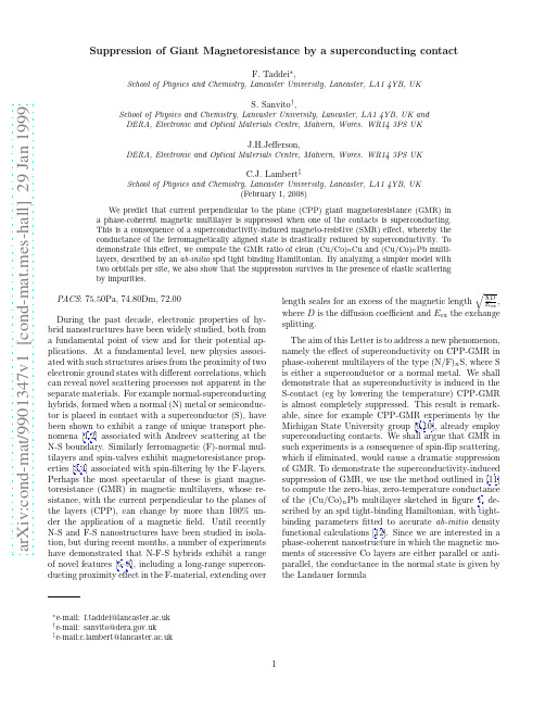
a r X i v :c o n d -m a t /9901347v 1 [c o n d -m a t .m e s -h a l l ] 29 J a n 1999Suppression of Giant Magnetoresistance by a superconducting contactF.Taddei ∗,School of Physics and Chemistry,Lancaster University,Lancaster,LA14YB,UKS.Sanvito †,School of Physics and Chemistry,Lancaster University,Lancaster,LA14YB,UK and DERA,Electronic and Optical Materials Centre,Malvern,Worcs.WR143PS UKJ.H.Jefferson,DERA,Electronic and Optical Materials Centre,Malvern,Worcs.WR143PS UKmbert ‡School of Physics and Chemistry,Lancaster University,Lancaster,LA14YB,UK(February 1,2008)We predict that current perpendicular to the plane (CPP)giant magnetoresistance (GMR)in a phase-coherent magnetic multilayer is suppressed when one of the contacts is superconducting.This is a consequence of a superconductivity-induced magneto-resistive (SMR)effect,whereby the conductance of the ferromagnetically aligned state is drastically reduced by superconductivity.To demonstrate this effect,we compute the GMR ratio of clean (Cu/Co)n Cu and (Cu/Co)n Pb multi-layers,described by an ab-initio spd tight binding Hamiltonian.By analyzing a simpler model with two orbitals per site,we also show that the suppression survives in the presence of elastic scattering by impurities.PACS :75.50Pa,74.80Dm,72.00During the past decade,electronic properties of hy-brid nanostructures have been widely studied,both from a fundamental point of view and for their potential ap-plications.At a fundamental level,new physics associ-ated with such structures arises from the proximity of two electronic ground states with different correlations,which can reveal novel scattering processes not apparent in the separate materials.For example normal-superconducting hybrids,formed when a normal (N)metal or semiconduc-tor is placed in contact with a superconductor (S),have been shown to exhibit a range of unique transport phe-nomena [1,2]associated with Andreev scattering at the N-S boundary.Similarly ferromagnetic (F)-normal mul-tilayers and spin-valves exhibit magnetoresistance prop-erties [3,4]associated with spin-filtering by the F-layers.Perhaps the most spectacular of these is giant magne-toresistance (GMR)in magnetic multilayers,whose re-sistance,with the current perpendicular to the planes of the layers (CPP),can change by more than 100%un-der the application of a magnetic field.Until recently N-S and F-S nanostructures have been studied in isola-tion,but during recent months,a number of experiments have demonstrated that N-F-S hybrids exhibit a range of novel features [5–8],including a long-range supercon-ducting proximity effect in the F-material,extending overlength scales for an excess of the magnetic lengthE ex ,where D is the diffusion coefficient and E ex the exchange splitting.The aim of this Letter is to address a new phenomenon,namely the effect of superconductivity on CPP-GMR in phase-coherent multilayers of the type (N/F)n S,where S is either a superconductor or a normal metal.We shall demonstrate that as superconductivity is induced in the S-contact (eg by lowering the temperature)CPP-GMR is almost completely suppressed.This result is remark-able,since for example CPP-GMR experiments by the Michigan State University group [9,10],already employ superconducting contacts.We shall argue that GMR in such experiments is a consequence of spin-flip scattering,which if eliminated,would cause a dramatic suppression of GMR.To demonstrate the superconductivity-induced suppression of GMR,we use the method outlined in [11]to compute the zero-bias,zero-temperature conductance of the (Cu/Co)n Pb multilayer sketched in figure 1,de-scribed by an spd tight-binding Hamiltonian,with tight-binding parameters fitted to accurate ab-initio density functional calculations [12].Since we are interested in a phase-coherent nanostructure in which the magnetic mo-ments of successive Co layers are either parallel or anti-parallel,the conductance in the normal state is given by the Landauer formulaG NN =e 2hR a ,(2)where R a =r σa r σ†a is the Andreev reflection coeffi-cient,which for a spin-singlet superconductor is inde-pendent of the spin σof the incident quasi-particle.In what follows,when the magnetic moments of adjacent Co layers are aligned (anti-aligned)we denote the con-ductances by G F NN ,G F NS (G A NN ,G ANS )and therefore theGMR ratios are given by M NN =(G F NN −G A NN )/G ANN ,M NS =(G F NS −G A NS )/G ANS .Consider first the case of quasi-ballistic transport in which there is no disorder within the layers,nor at the interface,but the widths of the Co layers are allowed to fluctuate randomly by 1atomic layer.Such a struc-ture is translationaly invariant in the direction ( r )par-allel to the layers,and the Hamiltonian is diagonal in a Bloch basis ( k ).Therefore the trace over scattering channels in equation (1)and (2)can be evaluated by computing the scattering matrix at separate k points.Figure 2a shows results for the GMR ratio in the normal and superconducting states,obtained by summing over 5·103k points,and clearly demonstrates a dramatic superconductivity-induced suppression of GMR.Figure 2b and 2c show results for the individual conductances (note the difference in scales)and demonstrate that the GMR ratio M NS is suppressed because G F NS is drasticallyreduced compared with G FNN .To understand this effect,consider the simplest possi-ble model of spin-dependent boundary scattering shown in figure 3,which in the limit of delta-function F lay-ers,reduces to the model used to describe the N-F-S experiment of [8].Fig 3a (3b)shows a cartoon of a majority (minority)spin,scattering from a series of potential barriers in successive aligned F layers.Since the minority spins see the higher barrier,one expects T F ↓<T F ↑.Figures 3c and 3d show the scattering poten-tials for anti-ferromagnetically aligned layers,for whichT A↑=T A ↓<T F ↑.For such an ideal structure,GMR arises from the fact that T F ↑≫T F ↓and T A↑.In the presence of a single superconducting contact this picture is drastically changed.For ferromagnetically aligned layers,figure 3e shows an incident majority electron scattering from a se-ries of low barriers,which Andreev reflects as a minority hole and then scatters from a series of high barriers (fig-ure 3f).The reverse process occurs for an incident minor-ity electron,illustrating the rigorous result that the An-dreev reflection coefficient is spin-independent.Figures 3g and 3h illustrate Andreev reflection in the anti-aligned state.The crucial point illustrated by these sketches is that in presence of a S contact for both the aligned (fig-ures 3e and 3f)and anti-aligned (figures 3g and 3h)states the quasi-particle scatters from N (=4in the figures)high barriers and N (=4)low barriers and therefore at the levelof a classical resistor model,one expects G F NS ≈G ANS .Of course the rigorous results of figure 2,obtained us-ing an spd Hamiltonian with 36orbitals per atomic site (spd ×2for spin ×2for particle-hole degrees of freedom)go far beyond this heuristic argument.In the case of aligned or anti-aligned F-layers the problem involves two independent spin fluids and therefore the Hamiltonian is block-diagonal with 18orbitals per site.The Hamilto-nian used to obtain these results is of the formH spd =H L +H LM +H M +H MR +H R ,(3)where H L (H R )describes a semi-infinite left-hand (right-hand)crystalline lead,H LM (H MR )is the coupling matrix between surface orbitals on the left (right)lead and the left (right)surface of the magnetic multilayer and H M is the tight-binding Hamiltonian describing the multilayer.Consider first the retarded Green’s function g =(E −H L −H R +i 0+)−1of the two decoupled semi-infinite leads.If the surfaces of the leads each contain M atoms,then H LM and H MR are 36M ×36M matri-ces and the portion of g involving only matrix elements between orbitals on the left and right lead surfaces is a (2×36M )×(2×36M )block diagonal matrix g S whosematrix element g Sij vanish for i,j belonging to different ing a semi-analytic form for g S derived in [11],the surface Green function G S for the leads plus multi-layer can be computed by first recursively decimating the Hamiltonian H LM +H M +H MR to yield a (72M ×72M )matrix of couplings ˜HM between surface orbitals of the leads,and then computing the inverseG S =[(g S )−1−˜HM ]−1.(4)Once the full surface Green’s function G S is known,the scattering matrix elements between open scattering channels are obtained using a generalized Fisher-Lee re-lations [15].For the calculation of figure 2,involving fcc crystalline leads aligned along the (110)direction the spd Hamiltonians for the bulk materials are known [12],but the hopping parameters at the interfaces between differ-ent materials are not currently available.As a simplest approximation,these surface couplings were chosen to be the geometric mean of their bulk values.Despite our use of a highly efficient recursive Green’s function technique to exactly evaluate the scattering ma-trix of a multilayer,currently available computing re-sources restrict such a calculation to systems with trans-lational invariance parallel to the planes.To demonstratethat the suppression of CPP-GMR is a generic feature of N-F-S hybrids and to study the effect of elastic impurity scattering,we now examine a reduced two band(s-d) model with a Hamiltonian matrixH= H o−h∆∆∗−H o∗+h .(5)In this model,hαβij=h iδijδαβδαd with h i the exchange splitting on site i for the d orbital,which vanishes if i be-longs to a N or S layer and is of magnitude h if i belongs to a F layer;∆αβij=∆iδijδαβwhere the superconduct-ing order parameter∆i vanishes if i belongs to a N or F layer and equals∆if i belongs to the S region(s-wave superconductivity);(H o)αβij=ǫαiδαβfor i=j,−γαβfor i,j nearest neighbors and(H o)αβij=0otherwise.Note that this model is the minimal model including the pos-sibility of s-d interband scattering,that has been shown to play a crucial rˆo le in describing the scattering prop-erties of a transition metal multilayer[11].ǫαi is chosen to be a random number,uniformly distributed between ǫα−w/2andǫα+w/2.We choose the parameters of the model tofit the conductance and the GMR obtained from the spd model for Cu/Co[11],namely(all quantities are expressed in eV)ǫs Cu=−7.8,ǫd Cu=−4.0,γss Cu=2.7,γdd Cu=0.85,γsd Cu=1.1,ǫs Co=−4.6,ǫd Co=−2.0,γss Co=2.7,γdd Co=0.85,γsd Co=0.9,h=1.6,∆=10−3, w=0.6.Figure4a shows results for the GMR ratios M NN and M NS and demonstrates that the suppression of CPP-GMR by superconductivity survives in the presence of disorder.We have investigated a range of higher disor-ders and system sizes andfind superconductivity-induced GMR suppression in all cases.The disorder used infig-ure4has been chosen to illustrate an additional novel feature,not so-far discussed in the literature,namely that ballistic majority spins can co-exist with diffusive minority spins.For a strictly ballistic structure,the con-ductance G is almost independent of length L and the product G·L varies linearly with L.This behavior oc-curs for the majority spin in the N-results offigure4b.In contrast,for minority spins the product G F↓NN ·L ex-hibits a plateau for L≥500AP,which is characteristic of diffusive behavior.The same plateaus are also present in the product G A NN·L and in the curves of G A NS·L and G F NS·L shown infigure4c.In summary we predict that the presence of a sin-gle superconducting contact destroys the sub-gap CPP-GMR of phase-coherent magnetic multilayer.This arises because superconductivity suppresses transport in the majority sub-band in the ferromagnetic alignment,but causes little effect in the antiferromagnetically aligned state.This drastic reduction in G F NS compared with G F NN is itself a remarkable superconductivity-induced magneto resistance effect.This suppression will be lifted at high biases andfinite temperatures,where transport occurs via both Andreev reflection and quasi-particle transmis-sion.Furthermore the presence of spin-flip scattering at the superconducting interface will destroy this effect,be-cause if the spin of an Andreev reflected hole isflipped by such process,before it traverses the multilayer,only the contribution to GMR from layers within a spin-flip scattering length of the N/S interface is suppressed. Acknowledgments:This work is supported by the EPSRC,the EU TMR Programme and the DERA.FIG.1.Scheme of the system considered:N-F multi-layer sandwiched between a normal (N)contact and a super-conducting (S)contact.In the calculation presented N=Cu,F=Co and S=Pb.2.04.0 6.08.010.0Cu thickness (atomic planes)−50.050.0150.0250.0G M R (%)NN NS2.04.0 6.08.010.0Cu thickness (atomic planes)0.00.10.20.30.4G p e r o p e n c h a n n e lAF minority F majority2.04.0 6.08.010.0Cu thickness (atomic planes)0.060.070.080.090.10G p e r o p e n c h a n n e lA F(a)(b)(c)FIG.2.GMR (a)and spin conductances of Cu/Co multi-layers as a function of the Cu thickness,in the case of normal contacts (b)and with one N contact replaced by a supercon-ducting (c)contact.The system is disorder-free in the layers,but the Co thickness is allowed to randomly fluctuate by 1atomic plane.Every point corresponds to the mean of 10different configurations.The error bars denote the standard deviation of the mean.G FNNG NNAG FNSG NSASSprocesses.Fig-ures 3a,3b,3c and 3d describes the transmission of spin elec-trons e ↑(↓)in a NN system.Figures 3e,3f,3g and 3h describe the NS case.Note that in the F case a majority (minority)spin electron e ↑(e ↓)is Andreev reflected as a minority (ma-jority)hole h ↓(h ↑).In the anti-aligned (A)case the path of the incoming electrons and outcoming holes is identical for both spins.The total number of large barriers is the same in the A and F case,and this produces GMR suppression.C o n d u c t a n c e *L e n g thTotal Length (atomic planes)G M R (%)C o n d u c t a n c e *L e n g t hFIG.4.GMR (a)and spin conductances of Cu/Co mul-tilayers calculated with the s-d two bands model,in the case of normal contacts (b)and with one N contact replaced by a superconducting (c)contact.The Co and Cu thicknesses are fixed and are respectively 15and 8atomic planes.Every point on the graph corresponds to an additional double bi-layer Co/Cu/Co/Cu.The on-site energy fluctuates randomly according with a normal distribution of width w =0.6,and the error bars are the standard deviation of the mean over 10random configurations.The unit cell is a square with 5×5atomic sites,and we consider 25k −points in the Brillouin zone.The horizontal line denotes GMR=0.。
巨磁电阻效应的英语

巨磁电阻效应的英语Giant magnetoresistance effect, huh? That's a mouthful! But let's break it down. Basically, it's this crazy phenomenon where the resistance of certain materials changes significantly when a magnetic field is applied.It's like they're super sensitive to magnets.Now, imagine this: you've got a material and you give it a little magnetic push. Suddenly, its resistance to electricity goes up or down by a huge amount. That's what we call giant magnetoresistance. And it's not just anylittle change; it's huge!One of the coolest things about this effect is how it's being used in tech. You know, like in those tiny sensors that can detect magnetic fields with incredible precision? They rely on this effect to work. It's like having a superpower to sense magnetic fields.And speaking of superpowers, imagine if we couldharness this effect for even more amazing things. Like, controlling robots with just our thoughts or something crazy like that. The possibilities are endless, really.So, in a nutshell, giant magnetoresistance is this fascinating effect where materials change their resistance a lot when you apply a magnetic field. It's not just a science experiment; it's shaping the future of technology in ways we can only imagine.。
岩土巨人介绍
岩土巨人介绍Ronald F. Scott加州理工学院教授1929– 2005 (2)Karl von Terzaghi (5)William John Macquorn Rankine(土力学学中的朗肯土压力理论的缔造者) (9)Arthur Casagrande (11)教授1929– 2005Ronald Fraser Scott, the Dotty and Dick Hayman Professor of Engineering, Emeritus, died on August 16, 2005. He was 76. An internationally acclaimed expert in soil mechanics and foundation engineering—or geotechnical engineering as it is now known—his research interests included the basic properties of soils and how they deform, the dynamics of landslides, the behavior of soil in earthquakes, the physical chemistry and mechanics of ocean-bottom soil, the physics of the freezing and thawing processes in soils, and the properties of the moon’s surface.Scott was born in London and grew up in Perth, Scotland. After ga ining a bachelor’s degree in civil engineering from Glasgow University in 1951 and an ScD in civil engineering (soil mechanics) from MIT in 1955, he worked with the U.S. Army Corps of Engineers on the construction of pavements on permafrost in Greenland, and with consulting engineers Racey, McCallum and Associates in Toronto, before joining Caltech as an assistant professor of civil engineering in 1958. Rising through the ranks, he became the Hayman Professor in 1987, and retired in 1998.On February 11, a memorial gathering in Scott’s honor was hosted by Norman Brooks (PhD ’54), Irvine Professor of Environmental and Civil Engineering, Emeritus. Caltech provost and professor of civil engineering and applied mechanics Paul Jennings, (MS ’60, PhD ’63, who to ok one of Scott’s soil mechanics classes as a graduate student), told the gathering that Scott had taken on a challenging field. ―As engineering materials, soils are simply not nice,‖ he said. ―They are complicated two-phase media, composed of a porous collection of particles and a fluid in thepores, typically water. As such, soils are kind of noneverything—nonlinear, nonelastic,nonhomogeneous, nonisotropic and therefore from the viewpoint of solid mechanics, noneasy.‖ But, he said, Scott was a Caltech type of engineer—half engineer, half scientist—who developed engineering tools and approaches based on a rigorous understanding of the fundamental mechanics involved.―This real-world messiness of soils translates to the classroom,‖ Jennings added. ―Around the country, soil mechanics courses are often not popular because the material resists the elegant mathematical simplifications that take one so far in other materials, like metals. Ron’s courses were different; they were well-appreciated and popular because he met the challenges of soil complexity head-on in his unique and interesting way.‖When he began teaching, there were no textbooks that suited Scott’s rigorous scientific approach based on the mathematical principles of solid and fluid mechanics, so he wrote several of his own, including Principles of Soil Mechanics (1963) and Foundation Analysis (1981).―His understanding of the theoretical issues was profound,‖ said James Knowles, the Kenan, Jr., Professor and Professor of Applied Mechanics, Eme ritus, ―but his work was always motivated by real-world problems and needs, and he accumulated much practical experience by consulting on such problems as landslides and soil liquefaction.‖ Living as he did in a region highly prone to landslides and earthq uakes, Scott’s expertise was called upon many times by consulting firms and government agencies. He was an advisor during the investigations that followed the Baldwin Hills Dam failure in Los Angeles in 1963 and the Bluebird Canyon landslide in Laguna Beach in 1978, and worked with Fred Raichlen, professor of civil and mechanical engineering, emeritus, to design the foundations of submarine wastewater outfalls to withstand earthquakes and high waves.Scott pioneered the use of centrifuges in soil dynamics, recognizing that the mechanical properties of soils depend on the pressures to which they’re subjected. The soil at the bottom of a large earthen dam, for example, is under an enormous amount of pressure from the weight of the soil above and around it. Laboratory-sized scale models, using much less soil, can’t reproduce this. Scott’s solution was to spin the model in a large centrifuge to achieve forces 50 to 100 times the acceleration due to gravity. His centrifuge also incorporated a computer-controlled shaking table that could model the intense motion of soil during an earthquake. ―This technology has been copied and refined at other labs around the world, but Ron was the originator,‖ said John Hall, professor of civil engineering and dean of students.In the 1960s, Scott’s expertise made him the ideal person to evaluate whether the surface of the moon would be safe to walk on. At the time, many people thought it was covered in a deep layer of fine dust, like talc, that wouldn’t support the weight of a human. As a principal investigator for Surveyors 3 and 7, two unmanned craft preparing the way for the Apollo 11 manned landing, hedesigned an instrument to examine the structure and load-bearing strength of the lunar soil.Scott’s box-shaped, claw-mou thed scoop, or ―soil mechanics surface sampler,‖ as NASA called it, was attached to a telescopic arm and could be moved around and lifted up and down by radio signals from Earth. The scoop could dig trenches, scrape up soil, and even lift large clods and drop them to break up the lumps. And by filling the scoop with soil and compressing it, Scott and JPL engineer Floyd Roberson could estimate its bearing strength.Surveyor 3 landed on the moon in 1967, and ―for the next two weeks,‖ Scott later wrote in th e February 1970 issue of E&S, ―Floyd and I happily and sleeplessly played with the lunar surface soil on the inside surface of a 650-foot-diameter crater.‖ The moon’s surface, they concluded, was like damp sand, and safe to walk on.When the time came for the manned landing, Scott waited anxiously on July 20, 1969, as Neil Armstrong climbed down the ladder of the lunar module Eagle. Everyone remembers Armstrong’s first words, ―That’s one small step for man, one giant leap for mankind,‖ but not many rememb er what he said next: ―I sink in about an eighth of an inch. I’ve left a print on the surface.‖ Those were the words Scott wanted to hear.There’s a postcript to this story. In November 1969, Apollo 12’s module landed close to Surveyor 3, and Charles Conrad and Alan Bean walked over to take a look at it. Conrad cut off the scoop and brought it back to Earth in two Teflon bags. Scott was present when the bags were opened. ―If I had known I would see it again,‖ Scott told E&S, ―I would have left the scoop c ompletely packed with lunar soil.‖The two V iking spacecraft that landed on Mars in 1976 also needed soil scoops, and again, Scott worked on those. As mentioned in E&S, No. 4, 2005, some of the soil collected by the scoops was used in a life-detection experiment designed by another Caltech faculty member, Norman Horowitz, who died shortly before Scott.Former students and colleagues at the memorial gathering mentioned Scott’s high standards. ―He did not tolerate sloppy or inaccurate research or engineer ing,‖ said Raichlen, ―and he had little patience with others who fell into that category.‖ A ―fiercely independent thinker,‖ Scott ―valued academic integrity above all else,‖ said John Ting, MS ’76, professor and dean of engineering at the University of Ma ssachusetts at Lowell. ―It wasn’t about the size of the research group, or the amount of funding—it was about the purity of the academic pursuit, and asking and then answering the key questions in the most elegant (and often the least expensive) way.‖ Two of Scott’s former graduate students, Hon-Yim Ko (MS ’63, PhD ’66), Murphy Professor ofEngineering at the University of Colorado at Boulder, and Thiam-Soon Tan (MS ’82, PhD ’86), associate professor of civil engineering at the National University of Singapore, also paid tribute to their mentor and friend. Many of the speakers remarked on Scott’s wit, his wry sense of humor, and his infectious laugh.Scott cultivated a love of literature and was an omnivorous reader, said his son, Grant, a professor of English at Muhlenberg College in Pennsylvania. And in a fitting tribute to his soil-engineer father, he said ―My father loved words—especially puns—where there was slippage in the slope of language, perhaps a kind of liquefaction where two letters supporting a dam of meaning gave way or there was a semantic friction or failure. He liked to see words collapse into other words, and watch as a seismic shift altered the landscape of a sentence.‖Scott was elected to the National Academy of Engineering in 1974. His awards included the American Society of Civil Engineers’ Walter L. Huber Civil Engineering Research Prize in 1969, the Norman Medal in 1972, and the Thomas A. Middlebrooks A ward in 1982. He was also selected to be the ASCE’s Terzaghi lecturer in 1983, and the British Geotechnical Society’s Rankine lecturer in 1987. Considered to be the two highest honors in Scott’s field, they are rarely awarded to a single person.He is survived by Pamela, his wife of over 46 years, sons Grant, Craig, and Rod, and seven grandchildren.可惜加州理工如今找不到几个教授再研究这个了,这个学科也湮灭在大牛的谈笑风生中了。
Giant magnetoresistive device with buffer-oxide la
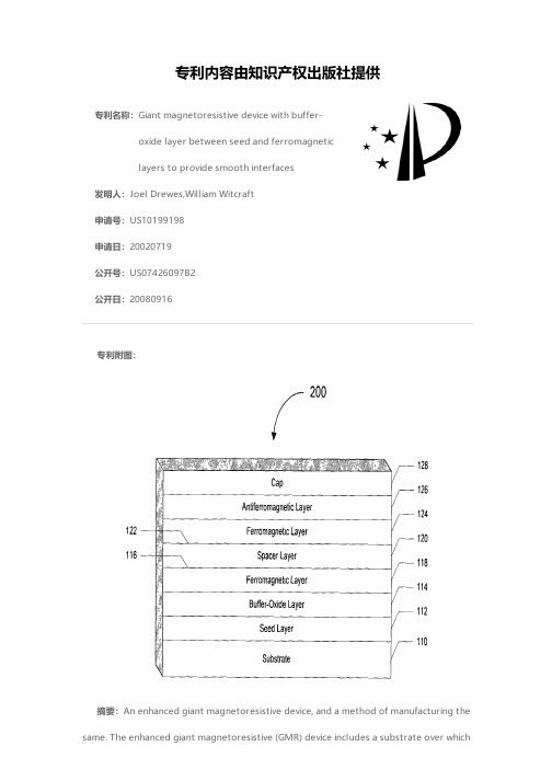
专利名称:Giant magnetoresistive device with buffer-oxide layer between seed and ferromagneticlayers to provide smooth interfaces发明人:Joel Drewes,William Witcraft申请号:US10199198申请日:20020719公开号:US07426097B2公开日:20080916专利内容由知识产权出版社提供专利附图:摘要:An enhanced giant magnetoresistive device, and a method of manufacturing the same. The enhanced giant magnetoresistive (GMR) device includes a substrate over whichis formed a seed layer. A buffer-oxide layer is formed over the seed layer. Formed over the buffer-oxide layer is a GMR stack. The GMR stack is formed as a three layer sandwich in which the two outside layers are fabricated from ferromagnetic materials, and the inner layer or spacer layer is formed from non-magnetic, conducting materials. The GMR stack may also take the form of spin valves, and/or other GMR stacks. The buffer-oxide layer may be various thicknesses and provide desirable texturing or non-waviness, both of which may allow for a thin spacer layer. Further, the buffer-oxide layer may be configured to prevent Néel-type-orange-peel coupling from dominating RKKY coupling in the GMR device, which may allow for a thin spacer layer.申请人:Joel Drewes,William Witcraft地址:Boise ID US,Minneapolis MN US国籍:US,US代理机构:McDonnell Boehnen & Hulbert & Berghoff LLP更多信息请下载全文后查看。
- 1、下载文档前请自行甄别文档内容的完整性,平台不提供额外的编辑、内容补充、找答案等附加服务。
- 2、"仅部分预览"的文档,不可在线预览部分如存在完整性等问题,可反馈申请退款(可完整预览的文档不适用该条件!)。
- 3、如文档侵犯您的权益,请联系客服反馈,我们会尽快为您处理(人工客服工作时间:9:00-18:30)。
Calculations of giant magnetoelectric effect in multiferroiccomposites of rare-earth-iron alloys and PZTby finite element methodGang Liu,Ce-Wen Nan *,Ning Cai,Yuanhua LinDepartment of Materials Science and Engineering,State Key Laboratory of New Ceramics and Fine Processing,Tsinghua University,Tsinghua park,Beijing 100084,ChinaReceived 26October 2003;received in revised form 24March 2004Available online 27April 2004AbstractMagnetoelectric effect of laminated composites of rare-earth-iron alloys (Terfenol-D)and lead–zirconate–titanate (PZT)is calculated by using finite element method.The dependences of the magnetoelectric response on the geometric configuration,the orientations of magnetostriction and polarization,and the applied magnetic field are presented for various sandwiched composites in details.The giant magnetoelectric effect predicted for the Terfenol-D/PZT com-posites is in agreement with predictions by a recent analytical method and recent experimental observations available.Ó2004Elsevier Ltd.All rights reserved.Keywords:Cermets;Magnetoelectricity;Magnetostriction;Piezoelectricity;Finite element analysis1.IntroductionMultiferroic composite materials (Nan and Clarke,1997;Nan et al.,2002)made by combining ferro-electric and ferromagnetic substances together have drawn significant interest due to their multifunction-ality,in which the coupling interaction between ferroelectric and ferromagnetic substances could produce new effects.Recently,the multiferroic composites in the systems of CoFe 2O 4/BaTiO 3(Harshe et al.,1993)and ferrite/lead–zirconate–titanate (PZT)(Bichurin et al.,1997;Srinivasan et al.,2002)have been found to exhibit extrinsic magnetoelectric (ME)effect which is characterized by the appearance of an electric polarization (ME H output)on applying a magnetic field (Nan,1994).This extrinsic ME response in the multiferroic composites results from a non-intuitive composite effect,i.e.,a 0þ0>0composite effect (Nan and Lin,2002).The ME effect has been widely investigated in over ten different crystal families (e.g.,antiferromag-netic Cr 2O 3,yttrium iron garnets,boracites,rare-earth ferrites,and phosphates)(Proceedings of the 3rd *Corresponding author.Tel.:+86-10-62773300;fax:+86-10-62773587.E-mail address:cwnan@ (C.-W.Nan).0020-7683/$-see front matter Ó2004Elsevier Ltd.All rights reserved.doi:10.1016/j.ijsolstr.2004.03.022/locate/ijsolstr4424G.Liu et al./International Journal of Solids and Structures41(2004)4423–4434International Conference on Magnetoelectric Interaction Phenomena in Crystals MEIPIC-3[Ferroelectrics 1997;204:1].).However,these monophase ME materials do not exhibit strong ME effect,and most of them have rather low Neel or Curie temperature far below room temperature.These make such single materials difficult tofind any practical applications in technology.Alternatively,strong ME effect can be produced in the multiferroic composites as mentioned above.In particular,the ME properties of the composites con-taining a giant magnetostrictive rare-earth-iron alloy(e.g.,SmFe2,TbFe2,or Tb1Àx Dy x Fe2(Terfenol-D) (Engdahl,2000),which is most widely used magnetostrictive alloy)have recently been calculated(Nan et al.,2001)by developing the Green’s function technique(Nan and Clarke,1997;Nan,1998;Nan and Weng,1999),and the predictions have revealed that both particulate composites with Terfenol-D embedded in a piezoelectric matrix such as poly(vinylidenefluoride-trifluorethylene)copolymer[P(VDF-TrFE)]or PZT and laminated composites of Terfenol-D/P(VDF-TrFE)or Terfenol-D/PZT can exhibit a giant ME(GME)effect which is about10–103times larger than that in the best known ME materials(such as Cr2O3and ferrite/piezoelectric ceramic composites).Subsequently,the laminated Terfenol-D/PZT composite made by stacking and bonding together the PZT and Terfenol-D disks with silver epoxy(Ryu et al.,2001a,b,2002)and laminated Terfenol-D/PVDF composite made by gluing the polarized PVDFfilm on Terfenol-D disks with conductive epoxy(Mori and Wuttig,2002)have been most recently found to exhibit such a GME sensitivity as predicted(Nan et al.,2001),which potentially makes such multiferroic composites particularly attractive for technological applications in actuators,transducers,and sensors.The GME response of such laminated composites is markedly dependent on the geometric configuration of the laminated composites and the orientations of magnetostriction and polarization in composites. Therefore,for the reason of providing a general guideline for achieving a more progressively desired level of the GME performance,it is urgent to reveal the dependences of the GME response on these important issues explicitly in a quantitative manner.Besides the Green’s function technique(Nan et al.,2001),an equivalent circuit approach(Dong et al.,2003a,b)has been recently proposed to simulate the thickness-dependence of the ME response of such sandwiched composites.However,a comprehensive and more accurate understanding on such GME response of the laminated composites is still in lack and the stress/ strain transfer from the magnetostrictive phase to the piezoelectric phase is not well shown.In this paper, we employ thefinite element method(FEM)and base on the stress/strain transfer to calculate the GME effect in the laminated composite of Terfenol-D and PZT and to present these quantitative dependences of the GME response on the geometric configuration and orientations of magnetostriction and polarization for these laminated composites.Our results are also applicable to other systems such as the laminated composites of PVDF and PZT.2.Theoretical frameworkConsider a perfectly bonded Terfenol-D/PZT laminated composite as shown in Fig.1.The response of the composite involving magnetoelectroelastic coupling effect can be described by the following general equations(Nan et al.,2001):r¼c eÀe T EÀc e k;ð1ÞD¼e eþj Eþa H;B¼lðe;E;HÞH;where r,e,D,E,B and H are the stress,strain,electric displacement,electricfield,magnetic induction,and magneticfield tensors,respectively;c,j and l are,respectively,the elastic stiffness at constantfield, dielectric constant tensor at constant strain and permeability tensor at constant strain;the permeability l depends on e,electric and magneticfields;e is the piezoelectric coefficient tensor(e T being the transposeof e );a is the ME coefficient;e k is the magnetostrictively induced strain of Terfenol-D,which is related to the magnetic field dependent magnetostriction constants (Nan and Weng,1999),k 100and k 111,defined respectively as the change in the normal strain in the [100]and [111]crystallographic directions when magnetization is along the [100]and [111]directions (Engdahl,2000).The strain e ,electric field,and magnetic field are respectively defined by the displacement u ,electric potential u ,and magnetic potential /,i.e.,e ij ¼1ðu i ;j þu j ;i Þ;E i ¼Àu ;i ;H i ¼À/;i :ð2ÞA state of static equilibrium in the absence of body forces and free electric charges leads tor ij ;j ¼0;D i ;i ¼0;B i ;i ¼0;ð3Þwhere the commas in the subscripts denote partial differentiation with respect to x j ,e.g.,r ij ;j ¼o r ij =o r j .In addition,by adopting a similar treatment to what have been successfully applied in the thermoelastoelectric coupling (Tzou and Ye,1994),the solution procedures for Eq.(1)in the present finite element method are divided into two steps as:(1)calculation of the magnetic field first,and then (2)analysis of the piezo-electricity which is incorporated with the influence from magnetostriction.This treatment is based on the assumption that the magnetic flux density in the composite is dominantly induced by the externally applied magnetic field.After these reasonable simplifications,the finite element formulation can be described as½K uu ½K u u ½K u u ½K uu f u g f u g ¼F u À½K uu f e k g Q À½K u/ f /gð4Þwhere the submatrices K uu ,K u u ,K uu and K u/indicate the elastic,piezoelectric,permittivity and magneto-electric coefficient matrices,respectively;F u and Q represent mechanical excitation vector and electric charge vector,respectively.The left-hand side includes the unknown displacement and electric potential at the vectors;the right-hand includes the excitation of the structure in terms of mechanical loads,applied magnetic loads and electric charge.Based on the above formulation,an eight-node brick finite element was developed and reduced integration was applied selectively for improving the accuracy of the numerical predictions.The body X could be subjected to either essential or natural mechanical and electric boundary condi-tions,or combination of them,on its boundary.Here,open circuit and ends clamped in the polarization direction (e.g.,the 3-direction in Fig.1),i.e.,D 3¼0and e 33¼0,are considered to comply with theG.Liu et al./International Journal of Solids and Structures 41(2004)4423–44344425experimental conditions.A commercial ANSYS software package was employed to execute the calcula-tions.3.Results and discussionOn applying an external magneticfield H3alone along the symmetric X3axis of the composite specimen (Fig.1),a ME output voltage E3is produced across the specimen along the X3direction.Thus the ME sensitivity along the X3direction,a E33,isa E33¼ÀE3=H3¼ÀaÃ33=jÃ33ð5Þwhere aÃ33and jÃ33are the effective magnetoelectric coefficient and dielectric constant of composites,respectively,and the ME sensitivity a E33represents thefigure of merit to assess the performance of a ME material for a magnetic device.The engineering magnetostriction of a Terfenol-D polycrystalline disk,e k, should be practically determined for a special sample and may be variable from each other(Engdahl,2000). Here we employ the same e kÀH behavior as presented before(Nan et al.,2001)and a detailed discussion about the influence of e kÀH behavior on the ME response will be presented subsequently.k100¼À100 ppm and k111¼1700ppm at saturation at H3¼2500Oe is used for Terfenol-D(Nan et al.,2001;Nan and Weng,1999).For the polycrystalline Terfenol-D disk,the saturation magnetostrictions parallel and per-pendicular H3,e k33and e k11,have been obtained as e k11¼e k22¼À530ppm and e k33¼1060ppm from the valuesof k100and k111(Nan and Weng,1999).Now for quantitative purposes,numerical calculations are carried out for the Terfenol-D/PZT composite.The properties of Terfenol-D and PZT used for calculations are given in Table1(Nan et al.,2001).3.1.Effect of geometric configuration of the compositesWefirst consider three different geometric configurations for the composite as schematically shown in Fig.2,i.e.,disk-shaped sample of one PZT layer sandwiched between two Terfenol-D layers(T–P–T(D), Fig.2a),disk-shaped sample with one Terfenol-D layer sandwiched between two PZT layers(P–T–P (D),Fig.2b),and block-shaped sample with one PZT brick bonded between two Terfenol-D bricks(T–P–T (B),Fig.2c).For calculations,the sizes of the disk-shaped samples are chosen as12mm in diameter and3 mm in thickness as used in experiment(Ryu et al.,2001a,b),and the sizes of the block-shaped samples are 12·3·3mm.The magnetostrictively induced strain in the Terfenol-D layers is passed along to the PZT Table1Properties of Terfenol-D and PZT-5A used in the present FEM simulationsProperties Terfenol-D a PZT-5A ac11(GPa)82121c12(GPa)4075.4c13(Gpa)4075.2c33(GPa)82111c44(GPa)3821.1e11=e06916e33=e06830l33=l051e31(C/m2)0)5.4e33(C/m2)015.8e15(C/m2)012.3a Nan et al.(2001).4426G.Liu et al./International Journal of Solids and Structures41(2004)4423–4434G.Liu et al./International Journal of Solids and Structures41(2004)4423–44344427layers,thus resulting in an electric polarization.Fig.3shows the dependence of a E33on the thickness or length ratio of Terfenol-D layer to the whole sample,t Ter-D=L(see Fig.2).As seen from Fig.3,the ME effect of the P–T–P(D)and T–P–T(B)composites are non-monotonically dependent on the t Ter-D=L with a maximum at t Ter-D=Lffi0:85,while the ME effect of the T–P–T(D) composite nearly linearly increases with t Ter-D=L.Of particularly interesting to note is that a surprisingly large ME effect,i.e.,a GME effect,is produced in all these three laminated composites with thick Terfenol-D layers but thin PZT layers.This trend is in an excellent agreement with that recently predicted by analytical Green’s function technique(Nan et al.,2001),and such a GME effect has recently been experi-mentally observed in the disc-shaped Terfenol-D/PZT/Terfenol-D composite(i.e.,a maximum a E33$5:90 V/cm Oe at t Ter-D=L¼0:8)(Ryu et al.,2001a,b).The calculated dependence of a E33on the thickness ratio of Terfenol-D phase is also validated in experiment(Ryu et al.,2001a,b).A comparison in Fig.3shows that the calculated a E33values are higher than those experimental ones available.The discrepancy between thecalculations and experiment is attributed mainly to the present assumption of a perfect bonding at inter-face.Any imperfectly interfacial bonding between these Terfenol-D and PZT layers by gluing together would lead to a loss of strain/stress transfers across the interface and thus a drop in a E33.Another significant reason for this discrepancy is that the properties(Table1)of Terfenol-D and PZT,especially the mag-netostriction of Terfenol-D,adopted for the present simulation could be different from those in experiment, which are not exactly known.Compared among the three differently constructed composites,it can be seen from Fig.3that the T–P–T (D)sample possesses the most super ME sensitivity while the T–P–T(B)sample the least.In the T–P–T(D) sample,the two outer Terfenol-D layers are also served as metal electrodes,and the effective dielectricconstant jÃ33of the T–P–T(D)sample is equal to j PZT33of the PZT.For the P–T–P(D)sample,the effectivedielectric constant can be simply expressed asjÃ33¼j PZT33=ð1Àt Ter-D=LÞ;ð6Þwhich is larger than the dielectric constant of the PZT,j PZT33.Thus the T–P–T(D)sample would exhibit alarger a E33than the P–T–P(D)sample with the same t Ter-D=L.As for the comparison between the sample T–P–T(B)with parallel mode and the series mode sample such as T–P–T(D),a corresponding comparison between calculated effective compressive stress r33in the3-direction of the two composites,as shown in Fig. 4,illustrates that r33of the T–P–T(B)sample is less than that of T–P–T(D)sample,thereby leading to a lower a E33of the T–P–T(B)than the T–P–T(D)sample.Under the present boundary conditions,both the absolute sizes,including thickness and diameter or length of all the three samples are found to exert no influences on a E33.This hints that,among all the geometric factors of the layered composites,only the relative thicknesses or lengths of Terfenol-D and PZT layers are critical to the ME sensitivity of the composites with perfectly interfacial bonding.3.2.Effect of orientations of magnetization and polarizationThere are two orientation cases of the magnetostriction and polarization in the composites.Thefirst one is that the principal magnetostriction of Terfenol-D could be along either the thickness direction or the radial(length)direction so that the laminated composites can be classified into three types(Ryu et al., 2001a,b)as:(a)both Terfenol-D layers having principal magnetostriction along the thickness direction4428G.Liu et al./International Journal of Solids and Structures41(2004)4423–4434(T–T,Fig.5a),(b)one along the thickness and the other along the radial direction (T–R,Fig.5b),and (c)both along the radial direction (R–R,Fig.5c).The polarization direction is still assumed to be along the 3-direction.The second case is shown in Fig.6,where there is a deflection angle between the directions of applied magnetic field and polarization in the composites.This deflection can be caused either by rotating the dc magnetic field on a stationary sample or by rotating the sample in a stationary dc magnetic field.For calculations,next we rotate the sample but fix the magnetic field direction in present static FEM simulation.For the first orientation case shown in Fig.5,the calculations (Fig.7)explicitly show that the values of a E 33for the T–T type composite are comparable with those for the R–R type composite,but both ofthemG.Liu et al./International Journal of Solids and Structures 41(2004)4423–443444294430G.Liu et al./International Journal of Solids and Structures41(2004)4423–4434exhibit a much larger a E33values than the T–R type composites,which is applicable for both the disk-shaped and the block-shaped composites.The predicted worst ME sensitivity for the T–R type composite has also been observed in experimental(see Fig.7)(Ryu et al.,2001a,b),but the calculated a little supe-riority of the T–T type composite over R–R type composite is not in agreement with the available experiment where the R–R type T–P–T(D)composite was found to exhibit a little higher a E33than the T–T type T–P–T(D)composite(Fig.7).The present boundary condition of mechanically clamped in the3-direction(polarization direction),which is somewhat different from the free condition in Ryu et al.’s experimental(Ryu et al.,2001a,b),could be the major reason for this little discrepancy.When the ends in the3-direction are mechanically clamped while the ends in other two directions can move freely the strain or stress in the composite is dominant along the3-direction due to an intense constraint in this direction. Correspondingly,the output E3is more dependent on the strain or stress in the clamped3-direction.The T–T type composites with the principal magnetostriction along the3-direction are sure to endure more intense stress in the clamped direction than the R–R type composite,as a result,the T–T type composite produces a larger output E3(see Fig.8)and thus a larger a E33than the R–R type composites.The reason for the far less ME sensitivity of the T–R type composites is due to a counteracted deformation between the two layers of Terfenol-D.Taking the T–R(D)sample as an example(Fig.5b),the top layer of Terfenol-D will contractalong the clamped direction,then the top interface bonding this Terfenol-D with PZT will move in the 3-direction.The bottom layer of Terfenol-D will expand along the clamped direction,then the bottom interface bonding this Terfenol-D with PZT will move in the 3-direction as well.Such deformations of the two outer Terfenol-D layers will drive the inner PZT layer to move wholly in a troop manner along the 3-direction with a result that the stresses from both top and bottom Terfenol-D are counteracted by each other.This means that no intense stress is imposed on PZT,thus a rather lower ME sensitivity appears in the T–R type composites.Now let us turn to the second orientation case shown in Fig.6.The T–T type T–P–T (D)and P–T–P (D)samples with the GME effect are taken as the model composites,and the samples are assumed to rotate in plane and in a counter clockwise way with the magnetic field being stationary,as shown in Fig.6.Fig.9clearly shows that the ME sensitivity of the composites is markedly dependent on the deflection angle h between the direction of the externally applied magnetic field and the polarization direction in the com-posites.The curves of a E 33vs h seem to be in a form of modified cosine function,and quantitatively,when7G.Liu et al./International Journal of Solids and Structures 41(2004)4423–443444314432G.Liu et al./International Journal of Solids and Structures41(2004)4423–4434the deflection angle increases from0°to45°,the a E33values decrease by over three times for both types of samples.It can be concluded that,under the definition of h,the deflection angle of zero,i.e.,the T–T type sample,is the most favorable to produce the GME sensitivity as discussed above(Fig.7).This is attributed to the reason that,when the principal magnetostriction is parallel with the3-direction,more constraint should be achieved.Further analyses reveal that the P–T–P(D)samples,although having a little lower ME sensitivity than the T–P–T(D)samples,exhibit a less decrease in a E33with h.In addition,the calculated relationships of a E33vs h are somewhat different from the Ryu et al.’s results(Ryu et al.,2001a,b),which might be due to difference between the present assumption of a mechanically clamped status along the 3-direction and the experimental case of boundary free condition.3.3.Effect of the applied magneticfieldIn all the calculations above,we keep the applied magneticfield constant as H3¼2500Oe for simplicity. As mentioned above,the engineering Terfenol-D polycrystals may undergo distinct magnetostrictive deformations with the applied magneticfield.For comparison,two differentfield-dependent magneto-striction constants(k100and k111)as presented before(Nan et al.,2001)were used for Terfenol-D(see curves B and C in Fig.8c of(Nan et al.,2001)).Thus two differentfield-dependent engineering mag-netostrictions,denoted as curves A and B in Fig.10,have been obtained for the polycrystalline Terfenol-D disks(see curves B and C in Fig.8b of(Nan et al.,2001)).The T–T type T–P–T and P–T–P samples with h¼0are chosen as the model samples.Fig.11shows the calculated dependence of a E33on the magneticfield for the two kinds of Terfenol-D disks(Fig.10).When the Terfenol-D follows the magnetostriction behavior A where the magnetostriction gets saturation in the lowfield range,the ME sensitivity of composites will change in a saddle shape with a maximum value in the low magneticfield range(A in Fig.11).At high magneticfield the magnetostriction becomes saturated,producing a nearly constant electricfield,therefore a E33decreases with increasing magneticfield.On the contrary,when the Terfenol-D follows the magnetostriction behavior B where the magnetostriction approaches saturation in highfield range,the ME sensitivity of composites monotonically increases(B in Fig.11).Both trends with bias have been observed in experiments(Ryu et al.,2001a,b;Wan et al.,2003)and are consistent with those predicted by analytical Green’s function techniques(Nan et al., 2001).The discrepancy between the two a E33vs H curves(Fig.11)directly results from the difference be-tween the two magnetostrictive behaviors for Terfenol-D layers(A and B in Fig.10).Thus the magneticG.Liu et al./International Journal of Solids and Structures41(2004)4423–44344433field dependence of a E33of the composites is dominated by the magneticfield dependence of magneto-striction of the Terfenol-D in the composites.4.ConclusionsThe ME effect in the laminated composites of magnetostrictive Terfenol-D stacked and perfectly bonded with piezoelectric PZT has been simulated byfinite element method.The calculated GME effect of these sandwiched composites is reasonably agreeable with available experimental results reported recently and recent predictions by the analytical Green’s function technique.The results reveal that the ME sensitivity of the laminated composites is strongly dependent on the relative thicknesses or lengths of Terfenol-D and PZT layers.In addition,the externally applied magneticfield is quantitatively found to exert marked influence on the magnetoelectric response not only by intensity variation but also by angle variation.When the applied magneticfield shares the same direction as the polarization,the maximium GME sensitivity is due for the T–T and R–R type laminated composites.When the Terfenol-D behaves in different magneto-striction paths,the variation of magnetoelectric sensitivity with the magneticfield intensity will exhibit as distinct curves.Such a GME sensitivity in the T–T and R–R type laminated composites makes these laminated composites be important materials for magnetic-electric devices,just as the technologically important piezoelectric and magnetostrictive composites extensively investigated.AcknowledgementsThis work was supported by the State Key Project of Fundamental Research of China(grant no. 2002CB613303and G2000067108)and from NSFC(grant no.50232030and50172026).ReferencesBichurin,M.I.,Kornev,I.A.,Petrov,V.M.,Lisnevskaya,I.,1997.Investigation of magnetoelectric interaction in composite.Ferroelectrics204,289–297.4434G.Liu et al./International Journal of Solids and Structures41(2004)4423–4434Dong,S.X.,Li,J.F.,Viehland,D.,2003a.Giant magneto-electric effect in laminate composites.IEEE Transactions on Ultrasonics Ferroelectrics and Frequency Control,1236–1239.Dong,S.X.,Li,J.F.,Viehland,D.,2003b.Longitudinal and transverse magnetoelectric voltage coefficients of magnetostrictive/ piezoelectric laminate composite:theory.IEEE Transactions on Ultrasonics Ferroelectrics and Frequency Control,1253–1261. Engdahl,G.,2000.Handbook of Giant Magnetostrictive Materials.Academic Press,New York.Harshe,G.,Dougherty,J.P.,Newnham,R.E.,1993.Theoretical modeling of3-0/0-3magnetoelectric composites.International Journal of Applied Electromagnetics in Materials4,145–171.Mori,K.,Wuttig,M.,2002.Magnetoelectric coupling in Terfenol-D/polyvilylidenedifluoride composites.Applied Physics Letter81, 100–101.Nan,C.W.,1994.Magnetoelectric effect in composites of piezoelectric and piezomagnetic phases.Physical Review B50,6082–6088. Nan,C.W.,Clarke,D.R.,1997.Effective properties of ferroelectric and/or ferromagnetic composites:a unified approach and its application.Journal of The American Ceramic Society80,1333–1340.Nan,C.W.,1998.Effective magnetostriction of magnetostrictive composites.Applied Physics Letter72,2897–2899.Nan,C.W.,Weng,G.J.,1999.Influence of microstructural features on the effective magnetostriction of composite materials.Physical Review B60,6723–6730.Nan,C.W.,Li,M.,Huang,J.H.,2001.Calculations of giant magnetoelectric effects in ferroic composites of rare-earth-iron alloys and ferroelectric polymers.Physical Review B63,144415.Nan,C.W.,Lin,Y.,2002.Microstructure-property linkages in multi-phase ceramics.Key Engineering Materials224–226,111–116. Nan,C.W.,Lin,Y.H.,Huang,J.H.,2002.Magnetoelectricity of multiferroic composites.Ferroelectrics280,319–329.Ryu,J.,Carazo,A.V.,Uchino,K.,Kim,H.E.,2001a.Magnetoelectric properties in piezoelectric and magnetostrictive laminate composites.Japanese Journal of Applied Physics40,4849–4951.Ryu,J.,Priya,S.A.,Carazo,A.V.,Uchino,K.,Kim,H.E.,2001b.Effect of the magnetostrictive layer on magnetoelectric properties in lead zirconate titanate/Terfenol-D composites.Journal of The American Ceramic Society84,2905–2908.Ryu,J.,Priya,S.A.,Uchino,K.,Kim,H.E.,2002.Magnetoelectric effect in composites of magnetostrictive and piezoelectric materials.Journal of Electroceramics,107–119.Srinivasan,G.,Rasmussen,E.T.,Levin,B.J.,Hayes,R.,2002.Magnetoelectric effects in ferrite-lead zirconate titanate layered composites:the influence of zinc substitution in ferrites.Physical Review B65,134402.Tzou,H.S.,Ye,R.,1994.Piezothermoelasticity and precision control of piezoelectric systems:theory andfinite element analysis.Journal of Vibration and Acoustics116,489–495.Wan,J.G.,Liu,J.M.,Chand,H.L.W.,Choy,C.L.,Nan,C.W.,2003.Giant magnetoelectric effect of a hybrid of magnetostrictive and piezoelectric composites.Journal of Applied Physics93,9916–9919.。