DiGas4000 Light五气体尾气分析仪
废气分析仪的使用流程

废气分析仪的使用流程1. 什么是废气分析仪废气分析仪是一种用于分析和检测废气成分和浓度的仪器设备。
它可以帮助我们了解废气的组成成分,判断废气处理设备的效果,并进行环境保护和安全监测等领域的工作。
废气分析仪的使用流程包括设备准备、样品采集、测量操作和结果分析等步骤。
下面将详细介绍每个步骤的具体内容。
2. 设备准备在进行废气分析之前,我们需要做好仪器设备的准备工作。
具体包括:•确认仪器设备的完好性,检查仪器各部分是否正常工作;•校准仪器,确保仪器的准确性和可靠性;•准备好所需的耗材和备品备件,防止出现故障时的延误;•清洁仪器设备,确保没有污染和杂质;•检查好电源和连接线路等电气设备,确保操作的安全性。
3. 样品采集在进行废气分析之前,我们需要采集样品进行分析。
样品采集是确保分析结果准确性的关键步骤。
下面是样品采集的一般步骤:1.根据采样点的位置和特性,确定采样工具和方法。
常用的采样工具包括气袋、吸附管、分析瓶等。
2.使用清洁的采样工具,避免污染样品。
3.根据采样点的特性,选择合适的采样时间和采样量。
一般情况下,应采集多个时间点或多段时间的样品,以获取更全面的数据。
4.注意采样点的环境条件,如温度、湿度等。
这些条件可能会对样品的分析结果产生影响。
5.将采集好的样品封存,以防止样品在运输过程中丢失或污染。
4. 测量操作在进行废气分析之前,我们需要进行测量操作。
下面是常用的测量操作步骤:1.打开废气分析仪的电源开关,等待仪器的预热时间(一般为数分钟)。
2.设置测量参数,包括采样时间、测量范围、测量单位等。
根据具体需求,可进行合适的调整。
3.将样品接入仪器,确保样品与仪器的连接稳固。
4.开始测量操作,观察仪器显示的数据,如浓度、分析结果等。
5.根据所需数据的准确性和实际情况,可以进行多次测量,并取多次测量的平均值。
5. 结果分析在测量操作完成后,我们需要对结果进行分析和解读。
下面是结果分析的一般步骤:1.对测量结果进行初步的观察和总结。
美国IR4000型汽车尾气分析仪

技术参数
北京利扬析仪
典型特征
便携耐用 同时测量 O2/NO/CO/CO2/HC 五气体 测量快速,精度满足及超过 OIML Class I 标准 计算 AFR、Lambda、GPM 独特的双排气管测量模式 自动及手动调零功能 气泵可手动开关切换 流量指示功能 废气稀释警告功能,用于提示发动机排气系统是 否存在空气泄漏 双过滤器系统设计,有效保护传感器 外置式 O2/NO 电化学传感器,维护方便 内置数据存储器 参数 HC CO CO2 NO O2 转速 AFR Lambda GPM 预热时间 RS232 接口 模拟输出 打印机 电源 温度要求 尺寸重量 仪器附件 0~10000ppm 0~10% 0~20% 0~5000ppm 0~25% 0~30000RPM 0~50 0~5 克/英里 约 5 分钟 有 8 路模拟输出 0~5VDC 或 0~10VDC 可选 内置 90~230VAC/50~60Hz;10VDC - 16VDC / 1.5A 正常, 3.5A 最大 环境温度 2℃~45℃;存储温度-40℃~75℃ 高 185 mm x 宽 295mm x 深 435mm;重约 6Kg 柔性取样探头、10 英尺取样管线、AC/DC 电源线、手册 描述 NDIR 红外传感器 NDIR 红外传感器 NDIR 红外传感器 电化学传感器 电化学传感器 测量值 计算值 计算值 计算值
文献检索实习作业1xin

文献检索实习作业1:1、什么是核心期刊,并结合自己的专业,查找《2008版北大中文核心期刊要目总览》,列出与本专业相关的核心期刊的刊名、ISSN号及在要目总览中的排名。
(1)核心期刊是期刊中学术水平较高的刊物,是我国学术评价体系的一个重要组成部分。
它主要体现在对科研工作者学术水平的衡量方面,如在相当一批教学科研单位申请高级职称、取得博士论文答辩资格、申报科研项目、科研机构或高等院校学术水平评估等,都需要在在核心期刊上发表一篇或若干篇论文。
核心期刊——某学科(或某领域)的核心期刊,是指那些发表该学科(或该领域)论文较多、使用率(含被引率、摘转率和流通率)较高、学术影响较大的期刊。
●刊名:测控术 (Measurement & Control Technology)ISSN号:ISSN 1000-8829排名:第七篇,工业技术——TP自动化技术,计算机技术。
●刊名:控制工程 (Control Engineering of China)ISSN号:ISSN 1671-7848排名:第七篇,工业技术——TP自动化技术,计算机技术。
●刊名:计算机仿真(Computer Simulation)ISSN号:ISSN 1006-9348排名:第七篇,工业技术——TP自动化技术,计算机技术2、请列出我校图书馆所购买的中外文电子资源数据库?●中文期刊:中国学术期刊全文数据库(中知网),中文科技期刊全文数据库(重庆维普),万方数字化期刊全文数据库(万方数据),人大复印报刊资料全文数据库,中国优秀党建期刊全文数据库;●中文图书:读秀知识库(收集图书近170万册),超星数字图书馆(收集近54万册电子图书),书生之家数字图书馆(收集近12万册电子图书);●外文文献资源:爱思唯尔英文期刊全文数据库(Elsevier SD),nature周刊,science online,施普林格学术期刊全文数据库(SPRINGERLINK ),EBSCOhost网络全文数据库(美国EBSCOhost),施普林格电子图书(收藏3万册外文电子图书),施普林格电子丛书(收录1000种外文电子丛书),国道外文专题数据超市(建筑、化学、企管、材料、先进制造专题),NSTL外文文献传递平台;3、利用“中国学术期刊全文数据库(CNKI)”查找2005年以来盐城工学院教师在核心期刊发表的论文数,并在检索结果中筛选“学科类别为”:计算机软件及应用或自动化技术相关的文献,记录下三篇文献的论文题名、作者、刊名和年卷期。
浅述在线激光气体分析仪在干熄焦循环气体检测中的应用
浅述在线激光气体分析仪在干熄焦循环气体检测中的应用在线激光气体分析仪在干熄焦循环气体检测中应用广泛,主要用于监测焦炉废气中的有害气体浓度,以确保生产过程的安全性和环保性。
本文将从干熄焦工艺的原理、在线激光气体分析仪的工作原理和优势以及在干熄焦循环气体检测中的应用方面进行阐述。
干熄焦是一种取代传统水熄焦工艺的高效率熄焦技术,在该工艺中,干净、干燥的氮气或其他惰性气体用于冲刷焦炉内部的高温焦炭,使其迅速冷却而不进行气化。
干熄焦工艺相比传统的水熄焦工艺具有循环氮气利用率高、焦炭冷却均匀、焦炉运行周期短等优点,因此得到了广泛应用。
在线激光气体分析仪是一种基于激光光谱学原理的气体监测仪器,广泛应用于工业生产、环境监测等领域。
其工作原理是通过激光束通过待测气体产生吸收、散射等现象,通过检测激光束在待测气体中的强度变化,进而推算出气体浓度。
在线激光气体分析仪具有测量范围宽、响应速度快、准确性高、稳定性好等特点,可以实时监测多种气体。
在线激光气体分析仪在干熄焦循环气体检测中的应用主要体现在以下几个方面:1.监测有害气体浓度:焦炉废气中含有一定量的有害气体,如一氧化碳、二氧化硫等。
在线激光气体分析仪可以实时监测焦炉废气中有害气体的浓度,及时发现异常情况并采取相应的措施。
2.优化循环氮气使用:干熄焦工艺中,循环氮气是十分重要的冷却介质。
在线激光气体分析仪可以对循环氮气进行实时监测,根据监测结果来优化循环氮气的使用方式,提高氮气的利用效率,降低生产成本。
3.过程控制和优化:在线激光气体分析仪可以实时监测焦炉废气中的气体成分和浓度,通过对监测数据的分析和处理,可以对干熄焦工艺进行优化控制。
比如,在焦炉内废气中检测到有害气体浓度过高时,可以及时调整处理措施,保证焦炉运行的安全性和环保性。
4.数据记录和报警系统:在线激光气体分析仪可以将监测数据进行记录和分析,并及时产生报警。
这样,操作人员可以及时获得有关焦炉废气的数据,并根据报警信息采取相应的措施,以确保生产过程的安全性。
LGA-4000激光气体分析仪

二、LGA-4000激光气体分析仪(一)、简介1、概要LGA-4000激光气体分析仪能够在各种高温、高粉尘、高腐蚀等恶劣的环境下进行现场在线的气体浓度测量。
2、测量原理LGA-4000激光气体分析仪是基于半导体激光吸收光谱(DLAS)气体分析测量技术的革新,能有效解决传统的气体分析技术中存在的诸多问题。
半导体激光吸收光谱(DLAS)技术利用激光能量被气体分子“选频”吸收形成吸收光谱的原理来测量气体浓度。
由半导体激光器发射出特定波长的激光束(仅能被被测气体吸收),穿过被测气体时,激光强度的衰减与被测气体的浓度成一定的函数关系,因此,通过测量激光强度衰减信息就可以分析获得被测气体的浓度。
3、系统组成LGA-4000激光气体分析仪由激光发射、光电传感和分析模块等构成,如图 1.2所示。
由激光发射模块发出的激光束穿过被测烟道(或管道),被安装在直径相对方向上的光电传感模块中的探测器接收,分析控制模块对获得的测量信号进行数据采集和分析,得到被测气体浓度。
在扫描激光波长时,由光电传感模块探测到的激光透过率将发生变化,且此变化仅仅是来自于激光器与光电传感模块之间光通道内被测气体分子对激光强度的衰减。
光强度的衰减与探测光程之间的被测气体含量成正比。
因此,通过测量激光强度衰减可以分析获得被测气体的浓度。
图4、●●●●5L激光发射光电传感控制模块及控制环境温度-30℃—60℃安装安装方式原位安装或旁路安装表1.1 LGA-4000激光气体分析仪规格和技术参数表种类测量下限测量范围种类测量下限测量范围O20.01%Vol. 0-1%V ol., 0-100%V ol. CO 40 ppm 0-8000ppm,0-100%V ol. CO220 ppm 0-2000ppm,0-100%V ol. H2O 0.03 ppm 0-3 ppm, 0-70%Vol.H2S 2 ppm 0-200 ppm, 0-30%V ol. HF 0.01 ppm 0-1 ppm, 0-10000 ppm HCL 0.01 ppm 0-7 ppm, 0-8000 ppm HCN 0.2 ppm 0-20 ppm,0-1%V ol. NH30.1 ppm 0-10 ppm, 0-1%V ol. CH410 ppm 0-200ppm, 0-10%V ol. C2H20.1 ppm 0-10 ppm, 0-70%V ol. C2H4 1.0 ppm 0-100ppm, 0-70%V ol.表1.2 LGA-4000激光气体分析仪常规气体测量种类及指标6、运行和维护LGA-4000系列气体分析系统内置了高性能微处理器,自动化程度非常高,操作简单易学。
Bosch AVENAR Detector 4000 洋 rangfire检测器说明书
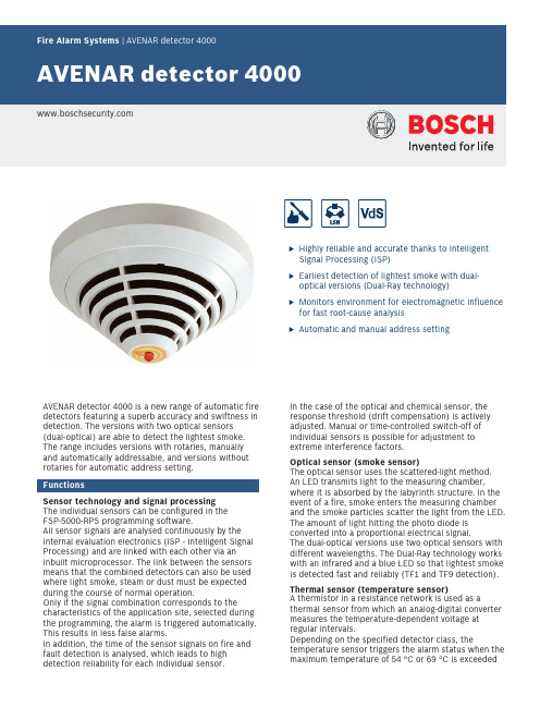
uHighly reliable and accurate thanks to Intelligent Signal Processing (ISP)uEarliest detection of lightest smoke with dual-optical versions (Dual-Ray technology)uMonitors environment for electromagnetic influence for fast root-cause analysisuAutomatic and manual address settingAVENAR detector 4000 is a new range of automatic fire detectors featuring a superb accuracy and swiftness in detection. The versions with two optical sensors (dual‑optical) are able to detect the lightest smoke.The range includes versions with rotaries, manually and automatically addressable, and versions without rotaries for automatic address setting.FunctionsSensor technology and signal processing The individual sensors can be configured in the FSP-5000-RPS programming software.All sensor signals are analysed continuously by the internal evaluation electronics (ISP - Intelligent Signal Processing) and are linked with each other via an inbuilt microprocessor. The link between the sensors means that the combined detectors can also be used where light smoke, steam or dust must be expected during the course of normal operation.Only if the signal combination corresponds to thecharacteristics of the application site, selected during the programming, the alarm is triggered automatically.This results in less false alarms.In addition, the time of the sensor signals on fire and fault detection is analysed, which leads to high detection reliability for each individual sensor.In the case of the optical and chemical sensor, the response threshold (drift compensation) is actively adjusted. Manual or time-controlled switch-off of individual sensors is possible for adjustment to extreme interference factors.Optical sensor (smoke sensor)The optical sensor uses the scattered-light method.An LED transmits light to the measuring chamber,where it is absorbed by the labyrinth structure. In the event of a fire, smoke enters the measuring chamber and the smoke particles scatter the light from the LED.The amount of light hitting the photo diode is converted into a proportional electrical signal.The dual-optical versions use two optical sensors with different wavelengths. The Dual-Ray technology works with an infrared and a blue LED so that lightest smoke is detected fast and reliably (TF1 and TF9 detection).Thermal sensor (temperature sensor)A thermistor in a resistance network is used as athermal sensor from which an analog-digital converter measures the temperature-dependent voltage at regular intervals.Depending on the specified detector class, thetemperature sensor triggers the alarm status when the maximum temperature of 54 °C or 69 °C is exceeded(thermal maximum), or if the temperature rises by a defined amount within a specified time (thermal differential).Chemical sensor (CO gas sensor)The main function of the gas sensor is to detect carbon monoxide (CO) generated as a result of a fire, but it will also detect hydrogen (H) and nitrous monoxide (NO). The sensor signal value is proportional to the concentration of gas. The gas sensor delivers additional information to effectively suppress deceptive values.Since the service life of the gas sensor is limited, the C sensor shuts down automatically after a maximum of 6 years of operation. The detector will then still operate as a multi-sensor detector with dual-optical and thermal sensor. It is recommended to exchange the detector immediately in order to keep the higher detection reliability of the version with C sensor. Improved LSN featuresAVENAR detector 4000 offers all the features of the improved LSN technology:•Flexible network structures, including T‑tappingwithout additional elements (no T-tapping feasible for versions without rotaries)•Up to 254 LSN improved elements per loop or stubline•Automatic or manual detector addressing, with orwithout auto-detection•Power supply for connected elements via LSN bus •Unshielded fire detection cable can be used •Cable length up to 3000 m (with LSN 1500 A)•Backwards compatibility to existing LSN systems and central units•Monitoring of environmental electromagnetic impactfor fast root-cause analysis (EMC values are displayed on the panel)In addition, the range offers all the established benefits of LSN technology. The panel programming software can be used to change the detection characteristics of the respective room utilization. Each configured detector can provide the following data:•Serial number•Contamination level of the optical section •Operating hours•Current analog values–Optical system values: current measured value of the scattered light sensor; the measuring range islinear and shows different degrees of pollution,from slight to heavy.–Contamination: the contamination value shows how much the current contamination value hasincreased relative to the original condition.–CO value: display of the currently measuredvalue.The sensor is self-monitoring. The following errors are indicated on the fire panel:•Fault indication in the event of the failure of thedetector electronics•Continuous display of contamination level duringservice•Fault indication if heavy contamination is detected(instead of triggering a false alarm)In the event of wire interruption or short-circuit,integrated isolators maintain the functional security of the LSN loop.In the event of an alarm, individual detector identification is transmitted to the fire panel.Further characteristics• A red flashing LED visible 360° indicates the alarm.•Connection to a remote indicator is possible.•The strain relief for cables in false ceilings preventsthe cables from being unplugged accidentally fromthe terminals after installation. The terminals forcable cross-sections up to 2.5 mm2 are very easilyaccessible.•The detectors have a dust-repellent labyrinth and cap construction. The chamber maid plug (an openingwith closing plug) on the bottom is used to clean the optical chamber with compressed air (not requiredfor the heat detector).•The detector bases no longer have to be directed due to the centralized position of the individual display.They also have a mechanical removal lock (can beactivated and deactivated).•Connectable to Bosch fire panels with the improved LSN system parameters.•You can use the DO detectors only with the PanelController MPC version B and higher. The PanelController MPC version A cannot be connected.•In LSN classic mode connectable to the LSN firepanels BZ 500 LSN, UEZ 2000 LSN, UGM 2020 and to other panels or their receiver modules with identical connection conditions, although with the previousLSN system parameters•During planning works, it is essential to adhere tonational standards and guidelines.•The detector can be painted (cap and base) andthereby adapted to the surrounding colour scheme.Note the information in the Painting Instructions.•Detectors of the 420 series can be replaced by allversions of the AVENAR detector 4000 without re-configuring the panel.Installation/configuration notes in accordance with VdS/VDE•The FAP‑425-DOTC-R, FAP‑425-DOT-R, FAP‑425-OT-R, and FAP‑425-OT versions are planned in accordance with the guidelines for optical detectors if operatedas optical detectors or as combined optical/thermal detectors (see DIN VDE 0833 Part 2 and VDS 2095)•If occasional deactivation of the optical unit(scattered light sensor) is required, planning must be based on the guidelines for heat detectors (seeDIN VDE 0833 Part 2 and VDS 2095)•When planning fire barriers according to DIBt, notethat the heat detector (FAH-425-T-R) must beconfigured in accordance with class A1R. ElectricalMechanicsEnvironmental conditionsFurther characteristicsLimitsHeed local guidelines. They overrule the following limits.Ordering informationFAP-425-O-R Smoke detector, opticalAnalog addressable detector with one optical sensor, manually and automatically addressable.Order number FAP-425-O-RFAP-425-OT-R Multisensor detector, optical/thermal Analog addressable detector with one optical and one thermal sensor, manually and automatically addressable.Order number FAP-425-OT-RFAH-425-T-R Heat detectorAnalog addressable heat detector with one thermal sensor, manually and automatically addressable. Order number FAH-425-T-RFAP-425-DO-R Smoke detector, dual-opticalAnalog addressable detector with two optical sensors, manually and automatically addressable.Order number FAP-425-DO-RFAP-425-DOT-R Multisensor detector, dual-optic/ther-malAnalog addressable detector with two optical sensors and one thermal sensor, manually and automatically addressable.Order number FAP-425-DOT-RFAP-425-DOTC-R Detector dual-optical/thermal/ chemicalAnalog addressable detector with two optical sensors, one thermal and one chemical sensor, manually and automatically addressable.Order number FAP-425-DOTC-R FAP-425-O Smoke detector, optical auto-addressable Analog addressable detector with one optical sensor, automatic address setting.Order number FAP-425-OFAP-425-OT Detector optic/thermal auto-addressable Analog addressable detector with one optical and one thermal sensor, automatic address setting.Order number FAP-425-OTAccessoriesMS 400 B Detector base with Bosch logoBosch-branded detector base for surface mounted and flush-mounted cable feedOrder number MS 400 BMS 400 Detector baseDetector base for surface mounted and flush-mounted cable feed, not branded.Order number MS 400FAA-420-SEAL Damp room seal, 10 pcsDamp room sealDelivery unit is 10.Order number FAA-420-SEALMSC 420 Base extension with damp room sealing Extension for detector bases with surface-mounted cable feedOrder number MSC 420MS 420 Base with springWith integrated jumper elements for checking the proper wiring during installation.Order number MS 420FAA-MSR420 Detector base with relaywith a change-over relay (Form C)Order number FAA-MSR420FNM-420-A-BS-WH Base sounder indoor, white analog addressable base sounder for indoor use, white, delivered without coverOrder number FNM-420-A-BS-WHFNM-420-A-BS-RD Base sounder indoor, redanalog addressable base sounder for indoor use, red, delivered with coverOrder number FNM-420-A-BS-RDFNM-420U-A-BSWH Base sounder uninterruptible, whiteuninterruptible analog addressable base sounder for indoor use, white, delivered without coverOrder number FNM-420U-A-BSWHFNM-420U-A-BSRD Base sounder uninterruptible in-door, reduninterruptible analog addressable base sounder for indoor use, red, delivered with coverOrder number FNM-420U-A-BSRD FAA-420-RI-DIN Remote indicator for DIN application For applications where the automatic detector is not visible, or mounted in false ceilings/floors.This version complies with DIN 14623.Order number FAA-420-RI-DINFAA-420-RI-ROW Remote indicatorFor applications where the automatic detector is not visible, or mounted in false ceilings/floors.Order number FAA-420-RI-ROWWA400 Wall bracketConsole for DIBt compliant mounting of detectors above doors etc., including detector baseOrder number WA400MH 400 Heating elementusable at locations where the functional safety of the detector might be impaired by condensationOrder number MH 400FMX-DET-MB Mounting bracketMounting bracket for installation in false floorsOrder number FMX-DET-MBSK 400 Protective cageprevents damageOrder number SK 400SSK400 Dust protection, 10pcsProtective dust cover for automatic point type detectors.Delivery unit is 10.Order number SSK400TP4 400 Label plate smallSupport plate for detector identification.Delivery unit is 50.Order number TP4 400TP8 400 Label plate largeSupport plate for detector identification, large. Delivery unit is 50.Order number TP8 400Represented by:Europe, Middle East, Africa:Germany:North America:Asia-Pacific:Bosch Security Systems B.V.P.O. Box 800025600 JB Eindhoven, The Netherlands Phone: + 31 40 2577 284****************************** Bosch Sicherheitssysteme GmbHRobert-Bosch-Ring 585630 GrasbrunnGermanyBosch Security Systems, Inc.130 Perinton ParkwayFairport, New York, 14450, USAPhone: +1 800 289 0096Fax: +1 585 223 9180*******************.comRobert Bosch (SEA) Pte Ltd, Security Systems11 Bishan Street 21Singapore 573943Phone: +65 6571 2808Fax: +65 6571 2699*****************************© Bosch Security Systems 2019 | Data subject to change without notice 136****1419|en,V23,25.Nov2019。
废气分析仪的使用方法流程

废气分析仪的使用方法流程1. 介绍废气分析仪是一种用于测量和分析废气排放中各种气体成分和浓度的仪器。
它广泛应用于环境保护、工业生产和燃气检测等领域。
本文将介绍废气分析仪的使用方法流程。
2. 使用前准备在使用废气分析仪之前,需要进行以下准备工作:•熟悉废气分析仪的型号和特性。
•确保废气分析仪的电源充足。
•准备好废气样品收集和传输设备。
3. 废气样品收集废气样品的收集是废气分析的关键步骤,正确的收集方式可以确保测试结果的准确性和可靠性。
以下是废气样品收集的一般步骤:1.确定采样点:根据实际情况选择合适的位置进行废气采样。
2.准备采样设备:根据废气成分及浓度的不同,选择合适的采样设备,如吸附管、袋装采样器等。
3.进行采样:将采样设备与废气排放口连接起来,确保气体可以顺利进入采样装置。
4.采样时间:根据实际情况确定采样时间,一般情况下,建议采样时间不少于30分钟。
5.停止采样:采样时间到达后,停止废气样品的采集。
6.封存样品:将采样器中的废气样品进行密封,以避免样品污染。
4. 废气分析仪的设置和校准在进行废气分析之前,需要对废气分析仪进行设置和校准。
以下是一般的设置和校准步骤:1.打开废气分析仪:按照说明书的要求,打开并启动废气分析仪。
2.进行废气分析仪的设置:根据实际需要,设置废气分析仪的参数,如温度、湿度、压力等。
3.废气分析仪的校准:使用标准气体对废气分析仪进行校准,确保仪器的准确性和可靠性。
5. 进行废气分析在完成废气样品的收集和废气分析仪的设置和校准之后,可以开始进行废气分析。
以下是废气分析的一般步骤:1.连接废气分析仪和采样器:将采样器中的废气样品与废气分析仪连接起来。
2.启动废气分析仪:按照说明书的要求,启动废气分析仪,并等待仪器的初始化过程。
3.废气分析设置:根据实际需要,选择分析的气体成分和浓度范围。
4.开始分析:按下开始按钮,废气分析仪会自动对废气样品进行分析。
5.记录结果:根据废气分析仪的显示结果,将分析结果记录下来。
LGA-4000激光气体分析仪
二、LGA-4000激光气体分析仪(一)、简介1、概要LGA-4000激光气体分析仪能够在各种高温、高粉尘、高腐蚀等恶劣的环境下进行现场在线的气体浓度测量。
2、测量原理LGA-4000激光气体分析仪是基于半导体激光吸收光谱(DLAS)气体分析测量技术的革新,能有效解决传统的气体分析技术中存在的诸多问题。
半导体激光吸收光谱(DLAS)技术利用激光能量被气体分子“选频”吸收形成吸收光谱的原理来测量气体浓度。
由半导体激光器发射出特定波长的激光束(仅能被被测气体吸收),穿过被测气体时,激光强度的衰减与被测气体的浓度成一定的函数关系,因此,通过测量激光强度衰减信息就可以分析获得被测气体的浓度。
3、系统组成LGA-4000激光气体分析仪由激光发射、光电传感和分析模块等构成,如图 1.2所示。
由激光发射模块发出的激光束穿过被测烟道(或管道),被安装在直径相对方向上的光电传感模块中的探测器接收,分析控制模块对获得的测量信号进行数据采集和分析,得到被测气体浓度。
在扫描激光波长时,由光电传感模块探测到的激光透过率将发生变化,且此变化仅仅是来自于激光器与光电传感模块之间光通道内被测气体分子对激光强度的衰减。
光强度的衰减与探测光程之间的被测气体含量成正比。
因此,通过测量激光强度衰减可以分析获得被测气体的浓度。
图4、●●●●5L激光发射光电传感控制模块及控制环境温度-30℃—60℃安装安装方式原位安装或旁路安装表1.1 LGA-4000激光气体分析仪规格和技术参数表种类测量下限测量范围种类测量下限测量范围O20.01%Vol. 0-1%V ol., 0-100%V ol. CO 40 ppm 0-8000ppm,0-100%V ol. CO220 ppm 0-2000ppm,0-100%V ol. H2O 0.03 ppm 0-3 ppm, 0-70%Vol.H2S 2 ppm 0-200 ppm, 0-30%V ol. HF 0.01 ppm 0-1 ppm, 0-10000 ppm HCL 0.01 ppm 0-7 ppm, 0-8000 ppm HCN 0.2 ppm 0-20 ppm,0-1%V ol. NH30.1 ppm 0-10 ppm, 0-1%V ol. CH410 ppm 0-200ppm, 0-10%V ol. C2H20.1 ppm 0-10 ppm, 0-70%V ol. C2H4 1.0 ppm 0-100ppm, 0-70%V ol.表1.2 LGA-4000激光气体分析仪常规气体测量种类及指标6、运行和维护LGA-4000系列气体分析系统内置了高性能微处理器,自动化程度非常高,操作简单易学。
- 1、下载文档前请自行甄别文档内容的完整性,平台不提供额外的编辑、内容补充、找答案等附加服务。
- 2、"仅部分预览"的文档,不可在线预览部分如存在完整性等问题,可反馈申请退款(可完整预览的文档不适用该条件!)。
- 3、如文档侵犯您的权益,请联系客服反馈,我们会尽快为您处理(人工客服工作时间:9:00-18:30)。
1、AVL 公司生产,可靠性好,故障率非常小。 2、精度高,真正国际一级精度。 3、具有高度的稳定性和重复性。 4、与 AVL 公司的其他设备具有很好的兼容性。 5、服务方便快捷。
3、技术数据
显示器
操作方式 打印机
接口 数据运载器
工作温度
湿度 工作电压 输入功率 体积 重量 仪器测量模式 符合的国家标准
4、AVL DiGas4000 Light 标配置清单
序号 1 2 3 4 5 6 7 8
配置组件名称 主机(含内置打印机) 取样探头 电源线 转速传感器及联线 塑封过滤器 颗粒过滤器 操作说明书 保修卡
数量 1(奥地利原装) 1(奥地利原装) 1(奥地利原装) 1 套(奥地利原装) 2(奥地利原装) 1(奥地利原装) 1套 1份
具有背景光、高分辨、高对比度、 高亮度的液晶图形(LCD) 显示器 ( VGA)。 6 个功能键、可外接标准 PC 键盘 可选的内置点阵式打印机 (带图形功能) 或外接打印机接口(爱普生 Epson-兼容机 ) RS232, PCMCIA 存储卡(标准 PCMCIA)用于测量功能选项设置、数据库、软件 更新和与 PC 的数据交换 +5 … +45° C 保持测量精确 -5 … +50° C 可用 最大为 95 %, 非密集型 195…253 V, 47…63 Hz 150 W 360 × 370 × 220 mm (长 ×宽 ×高) 14kg 常规(STD)与法规(OM)测量模式 GB18285-2005 附录 A 标准
分辨率 0.01%vol. 0.1%vol. 1ppm 1ppm 0.01%vol. 0.001 10rpm 1°C
2、产品性能特点
产品 特点 和 功能 介绍
仪器 的特 点及 优势
1
CO、HC、CO2、O2、NO、过量空气系数及转速测量
2
奥地利原装进口, OIML R99/ISO3930 一级精度
3
5、DiGas4000 Light 图片
特有标准 PCMCIA 操作系统软件升级接口
4
发动机排放系统诊断功能(可选)
5
大屏幕液晶显示
6
功能键操作,内置键盘输入,可外接 PC 键盘
7
适时自动校准系统
8
标定时间 365 天
9
多燃料10
内置打印机,具备通用打印接口,可外接打印机
11 RS232 通讯接口,具有数据处理软件(需 PC 机支持)
AVL DiGas4000 Light 五组份尾气分析仪
1、测量项目
原理 不分光 红外原 理 电化学 原理
测量数据 CO CO2 HC NO O2 过量空气系数 发动机转速 机油温度(可选)
测量范围 0--------10%vol. 0--------20%vol. 0--------20000ppm vol. 0--------5000ppm vol. 0--------25%vol. 0--------9.999 250------9990rpm 0--------150°C