1 GS-8800 Series Overview
8800系列数字无线测试系统入门指南说明书

8800 SeriesDigital Radio Test SystemGetting Started Manual8800 S e r i e s G e t t i n g S t a r t e d M a n u a l8800 SeriesDigital Radio Test System Getting Started ManualPUBLISHED BY VIAVI Solutions, Inc. COPYRIGHT VIAVI Solutions, Inc. 2019All rights reserved. No part of this publication may be reproduced, stored in a retrieval system, or transmitted in any form or byany means, electronic, mechanical, photocopying, recording or otherwise without the prior permission of the publisher.Original Printing Mar 2015 Aug 2015 Jan 2016 Dec 2019 Issue-2 Issue-3 Issue-4Product WarrantyRefer to /en-us/warranty-information for the Product Warranty information.Electromagnetic CompatibilityDouble shielded and properly terminated external interface cables must be used with this equipment when interfacing with the REMOTE Connector. For continued EMC compliance, all external cables must be shielded and three meters or less in length. Nomenclature StatementIn this manual, 8800 Series refers to the 8800 Series Digital Radio Test System.In this manual, Test Set, Digital Radio Test System or Unit refers to the 8800 Series Digital Radio Test System.Declaration of ConformityThe Declaration of Conformity Certificate included with the Unit should remain with the Unit. VIAVI recommends the operator reproduce a copy of the Declaration of Conformity Certificate to be stored with the Operation Manual for future reference.Software VersionVIAVI updates Test Set software on a routine basis. As a result, examples may show images from earlier software versions. Images are updated when appropriate.Complying with InstructionsThe safety precautions in this manual must be observed during installation and operation. VIAVI assumes no liability for failure to comply with any safety precaution outlined in this manual.DFARS/Restricted Rights NoticesIf software is for use in the performance of a U.S. Government prime contract or subcontract, software is delivered and licensed as “Commercial computer software” as defined in DFAR 252.227-7014 (Feb 2014), or as a “commercial item” as defined in FAR 2.101(a) or as “Restricted computer software” as defined in FAR 52.227-19 (Dec 2007) or any equivalent agency regulation or contract clause. Use, duplication or disclosure of Software is subject to the VIAVI standard commercial license terms, and non-DOD Departments and Agencies of the U.S. Government will receive no greater than Restricted Rights as defined in FAR 52.227-19(c)(1-2) (Dec 2007). U.S. Government users will receive no greater than Limited Rights as defined in FAR 52.227-14 (June 1987) or DFAR 252.227-7015 (b)(2) (November 1995), as applicable in any technical data.PrecautionsSAFETY FIRST - TO ALL OPERATIONS PERSONNELGeneral Conditions of UseThis product is designed and tested to comply with the requirements of IEC/EN61010-1 ‘Safety requirements for electrical equipment for measurement, control and laboratory use’ for Class I portable equipment and is for use in a pollution degree 2 environment. The equipment is designed to operate from installation supply Category II. The Digital Radio Test System should be protected from liquids such as spills, leaks, etc. and precipitation such as rain, snow, etc. When moving the equipment from a cold to hot environment, allow the temperature of the equipment to stabilize before the Unit is connected to an AC power supply to avoid condensation forming. The equipment must only be operated within the environmental conditions specified in the product specifications. This product is not approved for use in hazardous atmospheres or medical applications. If the equipment is to be used in a safety-related application, such as avionics or military applications, the suitability of the product must be assessed and approved for use by a competent person. Refer all servicing of the Unit to Qualified Technical Personnel.Safety Identification in Technical ManualThis manual uses the following terms to draw attention to possible safety hazards that may exist when operating or servicing this equipment:Safety Symbols in Manuals and on UnitsCase, Cover or Panel RemovalOpening the Case Assembly exposes the operator to electrical hazards that may result in electrical shock or equipment damage. Do not operate the Digital Radio Test System with the Case Assembly open.Equipment Grounding ProtectionImproper grounding of equipment can result in electrical shock.Power CordsThe AC Power Cord included with the Digital Radio Test System, or an appropriate replacement, should be used to connect the Digital Radio Test System to a grounded AC power supply. Failure to ground the Digital Radio Test System may expose the operator to hazardous voltage levels. To connect the Digital Radio Test System to a Class II (ungrounded) 2-terminal socket outlet, fit the power cord with either a 3-pin Class I plug used in conjunction with an adapter incorporating a ground wire or fit the power cord with a Class II plug containing an integral ground wire. The ground wire must be securely fastened to ground; grounding one terminal on a 2-terminal socket does not provide adequate protection. Power cords must be in good operating condition. Power cords must not be frayed or broken, nor expose bare wiring. Using a damaged power cord may expose the operator to hazardous voltage levels.International Power RequirementsThe AC power cord must meet local regulations and power requirements. Check with local standards and regulations to ensure the power cord being used meets all local safety regulations.Use Recommended Fuses OnlyUse only fuses specifically recommended for the equipment at the specified current and voltage ratings. Refer to Performance Specifications for fuse requirements and specifications.Internal BatteryThe Digital Radio Test System contains a Lithium Ion Battery.EMI (Electromagnetic Interference)Input OverloadFire HazardsStatic Sensitive ComponentsToxic HazardsBERYLLIABERYLLIUMCOPPERLITHIUMENVIRONMENTAL / PHYSICALOverall Dimensions343 mm (W), 293 mm (L), 146 mm (D)(13.50 in X 11.54 in X 5.75 in)Weight17 lbs. (7.71 kg)Temperature (Storage)-40°C to +71°CBattery must not be subjected to temperatures below -20°C, nor above +60°CTemperature (Operation)DC Only (Battery removed, contingent upon applied RFpower over time*)-20°C to +50°CBattery (typical based on internal temperature rise / usage of instrument*)-20°C to +50°CBattery must not be subjected to temperatures below -20°C, nor above +60°CAltitude4600 M (DC Operation) (MIL-PRF-28800F, Class 3)3048 M (AC Operation)Relative Humidity5% to 95% (MIL-PRF-28800F, Class 3)Shock (Functional)30 G (MIL-PRF-28800F, Class 3) Vibration5 to 500 Hz Random Vibrations (MIL-PRF-28800F, Class 3) Bench HandlingMIL-PRF-28800F, Class 3* Use reason when working with RF test instruments. All thermal ratings are dependent upon applied RF power.The Digital Radio Test System alarms once the internal temperature exceeds predetermined limits. Applying power continuously in high ambient temperature conditions resultin a heat build-up within the instrument.COMPLIANCE / SAFETYEMCEmissions and ImmunityMIL-PRF-28800FEN61326 Class AEN61000-3-2EN61000-3-3SafetyUL 6101-1EN61010-1CSA C22.2 No. 61010-1AC INPUT POWER (AC to DC Converter/Charger Unit) Voltage Range100 to 250 VAC, 3 A maximum, 47 to 63 HzVoltage Fluctuation<10% of nominal input voltageTransient OvervoltageInstallation Category IIUsage EnvironmentIndoor Use80% Maximum Relative Humidity for temperatures up to 31°C decreasing linearly to 50% RH at +40°C Installation Category IIPollution Degree 2Operating Temperature0°C to +40°CStorage Temperature-20°C to +85°CEMIEN55022 Class BEN61000-3-2 Class DSafetyUL 1950CSA 22.2 No. 234 and No. 950IEC 950/EN 60950DC INPUT POWERVoltage Range11 to 24 VdcMaximum Power55 WTypical Power30 WDC Fuse Requirement5 A, 32 Vdc, Mini-Blade, Type FBATTERYBattery TypeLithium Ion (Li Ion) Battery packBattery must not be subjected to temperatures below -20°C, nor above +60°COperation Time3 hours (Minimum Backlight - Still Viewable)2.5 hours (100% Backlight)Charge Time (using provided AC to DC Converter/Charger Unit)4 hours (Unit OFF) (Typical)4 hours (Unit ON) (Typical)Battery does not charge when Battery temperature is <0°C and >+45°C.Dead Battery (<10% capacity) is to be charged for20 minutes before operation on External DC Power.1. UNPACK UNIT STEP PROCEDURE1. Open the shipping container.2. Remove the top packing mold.3. Remove the Digital Radio Test System from thebottom packing mold.4. Remove the protective plastic bag from the DigitalRadio Test System and inspect the contents.8800S e r i e s G e t t i n g S t a r t e d M a n u a l2. INSTALLATION - CONNECTION TO POWERAC Power ConnectionThe External DC Power Supply should only be connected to a grounded AC supply outlet. The supplied External DC Power Supply operates over a voltage range of 100 to 240 VAC at 47 to 63 Hz. For AC operation, the AC Line Cable, connected to the External DC Power Supply, is equipped with a standard three-prong plug and must be connected to a properly grounded three-prong receptacle.BatteryThe Digital Radio Test System is powered by an internal Lithium Ion battery pack. The Digital Radio Test System is supplied with an External DC Power Supply which allows the operator to recharge the battery using AC power. The Digital Radio Test System can operate continuously on AC power via the External DC Power Supply, for servicing and/or bench tests. The internal battery is equipped to power the Digital Radio Test System for 2.5 hours of continuous use, after which time, the Digital Radio Test System battery needs recharging. When the BAT Indicator is GREEN, the battery is at 100% full charge. When the BAT Indicator is AMBER, the battery is charging. If the battery level is ≤5% (BAT Icon), a “Low Battery” warning message is displayed. The battery charger operates whenever the supplied External DC Power Supply or a suitable (11 to 24 Vdc) DC Power source is applied to the Digital Radio Test System. When charging, the battery reaches a 100% charge in approximately four hours. The internal battery charger allows the battery to charge between a battery temperature range of 0° to 45°C. The battery should be charged every three months (minimum) or disconnected for long term inactive storage periods of more than six months. The battery must be removed when conditions surrounding the Digital Radio Test System are <-20°C or >60°C. Allow 20 minutes for the battery to charge when turning the Digital Radio Test System ON from a dead battery condition.ﺔﻠﺳﻠﺳﻟا8800 Arrayﻲﻣﻗرﻟا وﯾدارﻟا رﺎﺑﺗﺧا مﺎظﻧمادﺧﺗﺳﻻا ءدﺑ لﯾﻟدﺞﺗﻧﻣﻟا نﺎﻣﺿﻊﺟار/en-us/warranty-information ﺞﺗﻧﻣﻟا نﺎﻣﺿﺑ ﺔﺻﺎﺧﻟا تﺎﻣوﻠﻌﻣﻟا ﺔﻓرﻌﻣﻟ. ﻲﺳﯾطﺎﻧﻐﻣورﮭﻛﻟا ﻖﻓاوﺗﻟاﻊﻣ ، ،ﺔﺑﺳﺎﻧﻣ تﺎﯾﺎﮭﻧﺑ ةدوزﻣو بﯾﺟﺣﺗﻟا ﺔﺟودزﻣ ﺔﯾﻧﯾﺑ تﻼﺑﺎﻛ مادﺧﺗﺳا بﺟﯾ.دﯾﻌﺑﻟا لﺻوﻣﻟﺎﺑ ﮫﻠﯾﺻوﺗ دﻧﻋ زﺎﮭﺟﻟا اذھ بﺟﯾ ،رﻣﺗﺳﻣ ﻲﺳﯾطﺎﻧﻐﻣورﮭﻛ ﻖﻓاوﺗ ﻖﯾﻘﺣﺗ لﺟأ نﻣ ﺎﮭﻟوط نوﻛﯾ نأ بﺟﯾ ﻲﺗﻟاو ﺔﯾﺟرﺎﺧﻟا تﻼﺑﺎﻛﻟا ﻊﯾﻣﺟ بﯾﺟﺣﺗ3 .لﻗأ وأ رﺎﺗﻣأ تﺎﺣﻠطﺻﻣﻟا نﺎﯾﺑﺔﻠﺳﻠﺳﻟا رﯾﺷﺗ ،لﯾﻟدﻟا اذھ ﻲﻓ8800 ﺔﻠﺳﻠﺳﻟا ﻲﻣﻗرﻟا وﯾدارﻟا رﺎﺑﺗﺧا مﺎظﻧ ﻰﻟإ8800. ﺔﻠﺳﻠﺳﻟا ﻲﻣﻗرﻟا وﯾدارﻟا رﺎﺑﺗﺧا مﺎظﻧ ﻰﻟإ تادﺣوﻟا وأ ﻲﻣﻗرﻟا وﯾدارﻟا رﺎﺑﺗﺧا مﺎظﻧ وأ رﺎﺑﺗﺧﻻا ﺔﻋوﻣﺟﻣ رﯾﺷﺗ ،لﯾﻟدﻟا اذھ ﻲﻓ8800. ﺔﻘﺑﺎطﻣﻟا نﻼﻋإﺔﻘﺑﺎطﻣﻟا نﻼﻋإ ةدﺎﮭﺷﺑ ظﺎﻔﺗﺣﻻا بﺟﯾةدﺣوﻟﺎﺑ .ﺎﮭﻌﻣ تﻘﻓرأ ﻲﺗﻟا ﻲﺻوﺗVIAVI ﻊﺟرﻣﻛ لﯾﻐﺷﺗﻟا لﯾﻟد ﻊﻣ ﺎﮭﺑ ظﺎﻔﺗﺣﻻاو ،ﺔﻘﺑﺎطﻣﻟا نﻼﻋإ ةدﺎﮭﺷ نﻣ ﺔﺧﺳﻧ جارﺧﺗﺳﺎﺑ لﻐﺷﻣﻟا.ﻲﻠﺑﻘﺗﺳﻣ ﺞﻣﺎﻧرﺑﻟا رادﺻإموﻘﺗVIAVI رﺎﺑﺗﺧﻻا ﺔﻋوﻣﺟﻣ تﺎﯾﺟﻣرﺑ ثﯾدﺣﺗﺑلﻛﺷﺑ ودير .ﺟﯾﺗﻧو ﻲﻓ ﺔﻘﺑﺎﺳ تﺎﯾﺟﻣرﺑ تارادﺻإ نﻣ روﺻ ضرﻋ مﺗﯾ دﻗ ،كﻟذﻟ ﺔﺔﻠﺛﻣﻷا . تﻗوﻟا ﻲﻓ روﺻﻟا ثﯾدﺣﺗ مﺗﯾ.بﺳﺎﻧﻣﻟا مازﺗﻟﻻاتادﺎﺷرﻹﺎﺑ لﯾﻐﺷﺗﻟاو بﯾﻛرﺗﻟا ءﺎﻧﺛأ ﺔﯾﻟﺎﺗﻟا ﺔﻣﻼﺳﻟا تﺎطﺎﯾﺗﺣا ةﺎﻋارﻣ بﺟﯾ. لﻣﺣﺗﺗ ﻻVIAVI .لﯾﻟدﻟا اذھ ﻲﻓ ﺔﺣﺿوﻣﻟا ﺔﻣﻼﺳﻟا تﺎطﺎﯾﺗﺣا نﻣ يﺄﺑ مازﺗﻟﻻا ﻲﻓ قﺎﻔﺧﻹا نﻋ ﺔﯾﻟوﺋﺳﻣ يأتﺎطﺎﯾﺗﺣﻻا–تﺎﯾﻠﻣﻌﻟا ﻲﻓ نﯾﻠﻣﺎﻌﻟا ﻊﯾﻣﺟﻟﻻوأ نﺎﻣﻷامادﺧﺗﺳﻼﻟ ﺔﻣﺎﻋ طورﺷ‘ﻲﻠﻣﻌﻣﻟا مادﺧﺗﺳﻻاو ،مﻛﺣﺗﻟاو ،سﺎﯾﻘﻟﺎﺑ ﺔﺻﺎﺧﻟا ﺔﯾﺋﺎﺑرﮭﻛﻟانﻣ ﺔﻟوﻣﺣﻣﻟا تادﻌﻣﻠﻟ‘تادﻌﻣﻠﻟ نﺎﻣﻷا تﺎﺑﻠطﺗﻣIEC/EN61010-1تﺎﺑﻠطﺗﻣ ﻊﻣ ﻖﺑﺎطﺗﯾﻟ هرﺎﺑﺗﺧاو ،ﺞﺗﻧﻣﻟا اذھ مﯾﻣﺻﺗ مﺗﮭﺟ ﺔﯾﺎﻣﺣ بﺟﯾزﺎﻲﻣﻗرﻟا وﯾدارﻟا رﺎﺑﺗﺧا مﺎظﻧII.نﻣﺔﺋﻔﻟاﺔﺋﻔﻟا نﻣ بﯾﻛرﺗﻟا تادﻌﻣ لﻼﺧ نﻣ لﻣﻌﻠﻟ زﺎﮭﺟﻟا اذھ مﯾﻣﺻﺗ مﺗIﺔﯾﻧﺎﺛﻟا ﺔﺟردﻟا نﻣ ثوﻠﺗ ﻰﻠﻋ يوﺗﺣﺗ ﺔﺋﯾﺑ ﻲﻓ مادﺧﺗﺳﻼﻟو ،.لﺑﻗ زﺎﮭﺟﻟا ةرارﺣ ﺔﺟرد تﺎﺑﺛ ﻰﻠﻋ ظﺎﻔﺣﻟا ﻰﻠﻋ صرﺣا ،ةرﺎﺣ ﺔﺋﯾﺑ ﻰﻟإ ةدرﺎﺑ ﺔﺋﯾﺑ نﻣ زﺎﮭﺟﻟا لﻘﻧ دﻧﻋ .ﺦﻟإ ،ﺞﻠﺛﻟاو ،رطﻣﻟا لوطھو ،.ﺦﻟا برﺳﺗﻟاو ،ﺔﻗارﻣﻟا تارطﻘﻟا لﺛﻣ لﺋاوﺳﻟا مادﺧﺗﺳﻼﻟ دﻣﺗﻌﻣ رﯾﻏ ﺞﺗﻧﻣﻟا اذھفﯾﺛﻛﺗ يأ ثودﺣ بﻧﺟﺗﻟ ددرﺗﻣﻟا رﺎﯾﺗﻟا يذ ﺔﻗﺎطﻟا ردﺻﻣﺑ ةدﺣوﻟا لﯾﺻوﺗ.ﺞﺗﻧﻣﻟا تﺎﻔﺻاوﻣ ﻲﻓ ةددﺣﻣﻟا ﺔﯾﺋﯾﺑﻟا فورظﻟا ﻲﻓ طﻘﻓ زﺎﮭﺟﻟا لﯾﻐﺷﺗ بﺟﯾ.صﺧﺷ موﻘﯾ نأ بﺟﯾ ﮫﻧﺈﻓ ،ﺔﯾرﻛﺳﻌﻟا تﻻﺎﻣﻌﺗﺳﻻا وأ ،نارﯾطﻟا تﺎﯾﻧورﺗﻛﻟإ لﺛﻣ نﻣﻷﺎﺑ ﻖﻠﻌﺗﻣ ضرﻏ يأ ﻲﻓ زﺎﮭﺟﻟا مادﺧﺗﺳا مﺗﯾﺳ نﺎﻛ اذإ.ةرطﺧﻟا ﺔﯾﺑطﻟا تﻻﺎﻣﻌﺗﺳﻻا وأ ءاوﺟﻷا ﻲﻓ.نﯾﻠھؤﻣ نﯾﯾﻧﻓ نﯾﻔظوﻣ ﻰﻟإ ةدﺣوﻟا ﺔﻧﺎﯾﺻ لﺎﻣﻋأ ﺔﻓﺎﻛ ﺔﻟﺎﺣإ بﺟﯾﮫﻣادﺧﺗﺳا دﺎﻣﺗﻋاو ،كﻟذﻟ ﺞﺗﻧﻣﻟا ﺔﻣﺋﻼﻣ ىدﻣ مﯾﯾﻘﺗﺑ لھؤﻣ..ﻊﻧﺻﻣﻟا ﺎھددﺣﯾ مﻟ ﺔﻘﯾرطﺑ رﺎﺑﺗﺧﻻا ﺔﻋوﻣﺟﻣ مادﺧﺗﺳا مﺗ اذإ ﺔﺑوﻠطﻣﻟا ﺔﯾﺎﻣﺣﻟا زﺎﮭﺟﻟا رﻓوﯾ ﻻ دﻗرﯾذﺣﺗﻲﻧﻔﻟا لﯾﻟدﻟا ﻲﻓ نﺎﻣﻷا فﯾرﻌﺗلﯾﻟدﻟا اذھ مدﺧﺗﺳﯾﺔﯾﻟﺎﺗﻟا:ﮫﺣﻼﺻإ وأ زﺎﮭﺟﻟا اذھ لﯾﻐﺷﺗ دﻧﻋ ثدﺣﺗ دﻗ ﻲﺗﻟا ﺔﻠﻣﺗﺣﻣﻟا نﺎﻣﻷا رطﺎﺧﻣ ﻰﻟإ هﺎﺑﺗﻧﻻا تﻔﻠﻟتﺎﺣﻠطﺻﻣﻟا.ﻖﺋارﺣﻟﺎﻛ ،تﺄﺷﻧﻣﻟا وأ زﺎﮭﺟﻟا ﻲﻓ فﻠﺗ ثودﺣ ﻰﻟإ يدؤﺗ دﻗ ﺎﮭﻠھﺎﺟﺗ مﺗ اذإ ﻲﺗﻟا ﺔطﺷﻧﻷا وأ فورظﻟا ددﺣﯾﮫﯾﺑﻧﺗ.ةﺎﻓوﻟا وأ ،ﺔﯾﺻﺧﺷ ﺔﺑﺎﺻإ ثودﺣ ﻰﻟإ يدؤﺗ دﻗ ﺎﮭﻠھﺎﺟﺗ مﺗ اذإرﯾذﺣﺗﻲﺗﻟا ﺔطﺷﻧﻷا وأ فورظﻟا ددﺣﯾتادﺣوﻟاو ،ﺔﻟدﻷا ﻲﻓ نﺎﻣﻷا زوﻣرﺔﺣوﻠﻟا وأ ،ءﺎطﻐﻟا وأ ،ﺔﺑﻠﻌﻟا ﺔﻟازإ|ﮫﯾﺑﻧﺗرﯾذﺣﺗ.ﺔﺣوﺗﻔﻣ ﺔﺑﻠﻌﻟا تﻧﺎﻛ اذإ هذھ رﺎﺑﺗﺧﻻا ﺔﻋوﻣﺟﻣ لﻐﺷﺗ ﻻ.زﺎﮭﺟﻟا فﻠﺗ وأ ﻲﺋﺎﺑرﮭﻛﻟا ﻖﻌﺻﻟا ﻰﻟإ يدؤﺗ نأ نﻛﻣﯾ ﺔﯾﺋﺎﺑرﮭﻛ رطﺎﺧﻣ ﻰﻟإ ﺔﺑﻠﻌﻟا ﺢﺗﻓ دﻧﻋ لﻐﺷﻣﻟا ضرﻌﺗﯾ دﻗزﺎﮭﺟﻠﻟ ﺔﯾﺿﯾرﺄﺗﻟا ﺔﯾﺎﻣﺣﻟاﮫﯾﺑﻧﺗرﯾذﺣﺗ|.ﻲﺋﺎﺑرﮭﻛﻟاﻖﻌﺻﻠﻟ ضرﻌﺗﻟا ﻰﻟإ زﺎﮭﺟﻠﻟ ﺊطﺎﺧﻟا ضﯾرﺄﺗﻟا يدؤﯾ دﻗﺔﻗﺎطﻟا كﻼﺳأ لﯾﺻوﺗ ﻲﻓ قﺎﻔﺧﻹا ﺔﻟﺎﺣ ﻲﻓ.يذ ضرؤﻣ ﺔﻗﺎط ردﺻﻣﺑ رﺎﺑﺗﺧﻻا ﺔﻋوﻣﺟﻣ لﯾﺻوﺗ دﻧﻋ مﺋﻼﻣ لﯾدﺑ يأ وأ ،ةدﺣوﻟا ﻊﻣ ﺔﻘﻓرﻣﻟا ددرﺗﻣﻟا رﺎﯾﺗﻟا تاذ ﺔﻗﺎطﻟا كﻼﺳأ مادﺧﺗﺳا بﺟﯾددرﺗﻣ رﺎﯾﺗلﺻوأ ،نﯾﻓرط ﻰﻠﻋ يوﺗﺣﯾ (ضرؤﻣ رﯾﻏ)II.ةرطﺧ ﺔﯾطﻟوﻓ تﺎﯾوﺗﺳﻣﻟ لﻐﺷﻣﻟا ضرﻌﺗﯾ دﻗ ،ضرﻷﺎﺑ رﺎﺑﺗﺧﻻا ﺔﻋوﻣﺟﻣﺔﺋﻔﻟا نﻣ مﻛﺣﺗ حﺎﺗﻔﻣﺑ زﮭﺟﻣ سﺑﻘﻣﺑ رﺎﺑﺗﺧﻻا ﺔﻋوﻣﺟﻣ لﯾﺻوﺗﻟII.لﻣﺎﻛﺗﻣ ﻲﺿرأ كﻠﺳ ﻰﻠﻋ يوﺗﺣﯾﺔﺋﻔﻟا نﻣ سﺑﺎﻘﺑ ﺔﻗﺎطﻟا كﻠﺳ لﺻوأ وأ ،ﻲﺿرأ كﻠﺳ ﻰﻠﻋ يوﺗﺣﯾ ﺊﯾﺎﮭﻣ ﻊﻣ ﮫﻣدﺧﺗﺳاو نوﻧﺳ3ﺔﺋﻔﻟا نﻣ سﺑﺎﻘﺑ ﺔﻗﺎطﻟا كﻠﺳIﻰﻠﻋ يوﺗﺣﯾطﺑر بﺟﯾﺎﮭﻟ ﺢﻣﺳﺗ ﺔﻟﺎﺣ ﻲﻓ ﺔﻗﺎطﻟا كﻼﺳأ نوﻛﺗ نأ بﺟﯾكﻠﺳﻟا.ﺔﯾﻓﺎﻛﻟا ﺔﯾﺎﻣﺣﻟا رﻓوﺗ ﻻ نﯾﻓرط ﻰﻠﻋ يوﺗﺣﯾ ذﺧﺄﻣ ﻲﻓ دﺣاو فرطﻟ ﻲﺿرﻷا لﯾﺻوﺗﻟا ﺔﯾﻠﻣﻋ نأ ثﯾﺣ ؛ضرﻷا ﻲﻓ مﺎﻛﺣﺈﺑ ﻲﺿرﻷاﺔﻟﺎﺣ ﻲﻓﺔﯾطﻟوﻓ تﺎﯾوﺗﺳﻣ ﻰﻟإ لﻐﺷﻣﻟا ضرﻌﺗﯾ دﻗ ،فﻟﺎﺗ ﺔﻗﺎط كﻠﺳ يأ مادﺧﺗﺳا.ﺔﯾرﺎﻌﻟا كﻼﺳﻷا مادﺧﺗﺳا مدﻋو ،رﺳﻛﻟا وأ ،ﻰﻠﺑﻟا نﻣ ﺔﻗﺎطﻟا كﻼﺳأ ﻰﻠﻋ ظﺎﻔﺣﻟا بﺟﯾ.دﯾﺟ لﻛﺷﺑ لﻣﻌﻟﺎﺑ.ةرطﺧﺔﯾﻟودﻟا ﺔﻗﺎطﻟا تﺎﺑﻠطﺗﻣﺔﯾﻠﺣﻣﻟا تﺎﻣﯾﻠﻌﺗﻟاو ،ﺔﻗﺎطﻟا تﺎﺑﻠطﺗﻣﻟ ﺎﻘﺑﺎطﻣ ددرﺗﻣﻟا رﺎﯾﺗﻟا وذ ﺔﻗﺎطﻟا كﻠﺳ نوﻛﯾ نأ بﺟﯾ. ﻊﯾﻣﺟ ﻊﻣ ﻲﺋﺎﺑرﮭﻛﻟا كﻠﺳﻟا ﻖﺑﺎطﺗ نﺎﻣﺿﻟ ﺔﯾﻠﺣﻣﻟا رﯾﯾﺎﻌﻣﻟاو ﺢﺋاوﻠﻟا ﻊﺟار نﺎﻣﻷا تﺎﻣﯾﻠﻌﺗ.ﺔﯾﻠﺣﻣﻟاطﻘﻓ ﺎﮭﺑ ﻰﺻوﻣﻟا رھﺎﺻﻣﻟا مدﺧﺗﺳا.ةددﺣﻣﻟا ﺔﯾطﻟوﻔﻟاو رﺎﯾﺗﻟا تﺎﻔﯾﻧﺻﺗ ﻲﻓ زﺎﮭﺟﻟ اذﮭﻟ ﺎﺻﯾﺻﺧ ﺎﮭﺑ ﻰﺻوﻣﻟا رھﺎﺻﻣﻟا طﻘﻓ مدﺧﺗﺳا.ﮫﺻﺋﺎﺻﺧو رﮭﺻﻣﻟا تﺎﺑﻠطﺗﻣﻟ ءادﻷا صﺋﺎﺻﺧ ﻊﺟار ﺔﯾﻠﺧادﻟا ﺔﯾرﺎطﺑﻟاﺔﯾرﺎطﺑ ﻰﻠﻋ هذھ رﺎﺑﺗﺧﻻا ﺔﻋوﻣﺟﻣ يوﺗﺣﺗموﯾﺛﯾﻟ .نوﯾأ EMI(ﻲﺳﯾطﺎﻧﻐﻣورﮭﻛﻟا لﺧادﺗﻟا) ) ﻲﺳﯾطﺎﻧﻐﻣورﮭﻛﻟا لﺧادﺗﻠﻟ اردﺻﻣ تارﺎﺷﻹا تادﻟوﻣ نوﻛﺗ نأ نﻛﻣﯾEMI لﺎﺻﺗﻻا تﻼﺑﻘﺗﺳﻣ ﻲﻓ ( . ثودﺣ ﻰﻟإ ﺔﻟوﻘﻧﻣﻟا تارﺎﺷﻹا ضﻌﺑ يدؤﺗ نأ نﻛﻣﯾ لﺎﯾﻣأ ةدﻋ ﺔﻓﺎﺳﻣ ﻰﺗﺣ لﺎﺻﺗﻻا ﺔﻣدﺧ ﻲﻓ لﺧادﺗو ،شﯾوﺷﺗ. يأ نﺎﻌﻣﺈﺑ صﺣﻔﯾ نأ زﺎﮭﺟﻟا اذﮭﻟ مدﺧﺗﺳﻣ يأ ﻰﻠﻋ بﺟﯾ يأ ﻲﻓ عﺎﻌﺷإ ثودﺣ ﻰﻟإ يدؤﺗ ﺔﯾﻠﻣﻋلﺎﺻﺗﻻا ﻲﻓ ﺔﻠﻣﺗﺣﻣ لﺧادﺗ تﻼﻛﺷﻣ يأ ثودﺣ بﻧﺟﺗﻟ ﺔﻣزﻼﻟا تﺎطﺎﯾﺗﺣﻻا ذﺎﺧﺗا ﮫﯾﻠﻋ نﯾﻌﺗﯾ ﮫﻧإ ﺎﻣﻛ ،(ةرﺷﺎﺑﻣ رﯾﻏ وأ ةرﺷﺎﺑﻣ ﺔﻘﯾرطﺑ) ةرﺎﺷإ. ﮫﯾﺑﻧﺗلﺎﺧدﻺﻟ طرﻔﻣﻟا لﯾﻣﺣﺗﻟالﺎﺧدﻹا تﻼﺻوﻣﻟ لﺎﺧدﻹا تﺎﻔﯾﻧﺻﺗ ﻰﺻﻗأ ﻰﻠﻋ فرﻌﺗﻠﻟ ﺞﺗﻧﻣﻟا صﺋﺎﺻﺧ ﻊﺟارANT وT/R . ﮫﯾﺑﻧﺗ ﻖﺋارﺣﻟا رطﺎﺧﻣلادﺑﺗﺳﻻا دﻧﻋ نﯾﺣﯾﺣﺻﻟا فﯾﻧﺻﺗﻟاو عوﻧﻟا تاذ رھﺎﺻﻣﻟا طﻘﻓ مادﺧﺗﺳا مﺗﯾ ﮫﻧأ نﻣ دﻛﺄﺗ. لﺻوﻣ ﻲﻓ رﮭﺻﻣ ﻰﻠﻋ يوﺗﺣﯾ لﻣﺎﻛﺗﻣ ﺎﺳﺑﺎﻗ مدﺧﺗﺳﺗ تﻧﻛ اذإ نأ نﻣ دﻛﺄﺗﻓ ،دادﻣﻹا.زﺎﮭﺟﻟا اذﮭﻟ رﺎﯾﺗﻟا تﺎﺑﻠطﺗﻣ ﻊﻣ ﺊﻓﺎﻛﺗﻣ رﮭﺻﻣﻟا فﯾﻧﺻﺗ رﯾذﺣﺗلﺎﺧدﻺﻟ طرﻔﻣﻟا لﯾﻣﺣﺗﻟامﻣﺳﺗﻟا رطﺎﺧﻣموﯾﻠﯾرﯾﺑﻟاموﯾﻠﯾرﯾﺑﻟا سﺎﺣﻧموﯾﺛﯾﻠﻟاتﺎﻔﺻاوﻣﻟاﺔﯾدﺎﻣﻟا / ﺔﯾﺋﯾﺑﻟاﻊﺿﺧﺗ)(.ﮫﯾﺑﻧﺗ نودﺑ رﯾﯾﻐﺗﻠﻟ تﺎﻔﺻاوﻣﻟا ﺔﯾﻟﺎﻣﺟﻹا دﺎﻌﺑﻷا343 ،(ضرﻋ) مﻠﻣ293 ،(لوط) مﻠﻣ146 (ﻖﻣﻋ) مﻠﻣ)13.50 ﺔﺻوﺑX 11.54 ﺔﺻوﺑX 5.75 (ﺔﺻوﺑ نزوﻟا17 لطر )7.71 (مﺟﻛ (نﯾزﺧﺗﻟا) ةرارﺣﻟا ﺔﺟرد-40°C ﻰﻟإ+71°C نﻣ لﻗأ ةرارﺣ تﺎﺟردﻟ ﺔﯾرﺎطﺑﻟا ضرﻌﺗﺗ ﻻأ بﺟﯾ-20°C نﻣ ﻰﻠﻋأ وأ ،+60°C.(لﯾﻐﺷﺗﻟا) ةرارﺣﻟا ﺔﺟردددرﺗ ﺔﻗﺎط ﻰﻠﻋ دﻣﺗﻌﺗ ،ﺔﯾرﺎطﺑﻟا ﺔﻟازإ مﺗﯾ) طﻘﻓ رﺷﺎﺑﻣﻟا رﺎﯾﺗﻟا وﯾدارﻟا(*تﻗوﻟا رﺑﻋ ﺔﻣدﺧﺗﺳﻣﻟا -20°C ﻰﻟإ+50°C مادﺧﺗﺳا و ﺔﯾﻠﺧادﻟا ةرارﺣﻟا ﺔﺟرد عﺎﻔﺗرا ﻰﻠﻋ دﻣﺗﻌﺗ ﺔﯾدﺎﻋ) ﺔﯾرﺎطﺑﻟا(*زﺎﮭﺟﻟا-20°Cﻰﻟإ+50°Cبﺟﯾنﻣ لﻗأ ةرارﺣ تﺎﺟردﻟ ﺔﯾرﺎطﺑﻟا ضرﻌﺗﺗ ﻻأ -20°C نﻣ ﻰﻠﻋأ وأ ،+60°C . عﺎﻔﺗرﻻا:رﺷﺎﺑﻣ رﺎﯾﺗ لﯾﻐﺷﺗ4600 M )(MIL-PRF-28800F ﺔﺋﻔﻟا ،3((ددرﺗﻣ رﺎﯾﺗ لﯾﻐﺷﺗ)3048 M ﺔﯾﺑﺳﻧﻟا ﺔﺑوطرﻟا5% to 95% )MIL-PRF-28800F ، ﺔﺋﻔﻟا3((.ﮫﯾﺑﻧﺗ نودﺑ رﯾﯾﻐﺗﻠﻟ تﺎﻔﺻاوﻣﻟا ﻊﺿﺧﺗ) ﺔﯾﻔﯾظو ،ﺔﻣدﺻﻟا30 G )MIL-PRF-28800F ﺔﺋﻔﻟا ،3( زازﺗھﻻاﺔﯾﺋاوﺷﻋ تازازﺗھا5 ﻰﻟإ500 ) زﺗرھMIL-PRF-28800F – ﺔﺋﻔﻟا3(MIL-PRF-28800F ﺔﺋﻔﻟا ،3 ﺔﻟوﺎط ﻰﻠﻋ زﺎﮭﺟﻟا مادﺧﺗﺳاMIL-PRF-28800F ﺔﺋﻔﻟا ،3 ﻲﻛﻠﺳﻼﻟا ددرﺗﻟا رﺎﺑﺗﺧا ةزﮭﺟأ مادﺧﺗﺳا دﻧﻋ ﻖطﻧﻣﻟﺎﺑ نﻌﺗﺳا. ﺔﯾرارﺣﻟا تﺎﻔﯾﻧﺻﺗﻟا ﻊﯾﻣﺟﻓﺔﻠﻣﻌﺗﺳﻣﻟا ﻲﻛﻠﺳﻼﻟا ددرﺗﻟا ﺔﻗﺎط ﻰﻠﻋ دﻣﺗﻌﺗ . توﺻ ﻲﻣﻗرﻟا وﯾدارﻟا رﺎﺑﺗﺧا مﺎظﻧ ﻖﻠطﯾﺎﻔﻠﺳ ةردﻘﻣﻟا دودﺣﻟا ﺔﯾﻠﺧادﻟا ةرارﺣﻟا ﺔﺟرد زوﺎﺟﺗﺗ نأ درﺟﻣﺑ ﮫﯾﺑﻧﺗ. لﺎﻣﻌﺗﺳا يدؤﯾ دﻘﻓ ةدﺎﯾز ﻰﻟإ ﺔﯾﻟﺎﻌﻟا ﺔطﯾﺣﻣﻟا ةرارﺣﻟا تﺎﺟرد فورظ ﻲﻓ رارﻣﺗﺳﺎﺑ ﺔﻗﺎطﻟالﺧاد ﺔﻧوﺧﺳﻟا.زﺎﮭﺟﻟاﻲﺳﯾطﺎﻧﻐﻣورﮭﻛﻟاﻖﻓاوﺗﻟاﺔﻧﺎﺻﺣو تﺎﺛﺎﻌﺑﻧا MIL-PRF-28800F EN61326 ﺔﺋﻓA EN61000-3-2EN61000-3-3ﺔﻣﻼﺳﻟاUL 61010-1UL61010-1CSA C22.2 No. 61010-1تﺎﻔﺻاوﻣﻟا(ﻊﺑﺎﺗ) ددرﺗﻣ رﺎﯾﺗ تاذ لﺎﺧدإ ﺔﻗﺎط) رﺎﯾﺗ ﻰﻟإ ددرﺗﻣ رﺎﯾﺗ نﻣ لوﺣﻣ(نﺣﺷﻟا ةدﺣو/رﺷﺎﺑﻣ ﺔﯾطﻟوﻓ قﺎطﻧ100 ﻰﻟإ250 رﺷﺎﺑﻣ رﺎﯾﺗ طﻟوﻓVAC ،3 ،ﻰﺻﻗأ دﺣﺑ رﯾﺑﻣأ47 زﺗرھﻰﻟإ63 زﺗرھ ﺔﯾطﻟوﻔﻟا بﻠﻘﺗ>10ﻲﻣﺳﻻا لﺎﺧدﻹا ﺔﯾطﻟوﻓ نﻣ % رﺑﺎﻌﻟا ﺔﯾطﻟوﻔﻟا طرﻓبﯾﻛرﺗﻟا ﺔﺋﻔﻟ2 مادﺧﺗﺳﻻا ﺔﺋﯾﺑﻲﻠﺧاد مادﺧﺗﺳا 80 ﻰﻟإ لﺻﺗ ﻲﺗﻟا ةرارﺣﻟا تﺎﺟردﻟ ﻰﺻﻗﻷا ﺔﯾﺑﺳﻧﻟا ﺔﺑوطرﻟا دﺣ %ﻰﻟإ ﻲطﺧ لﻛﺷﺑ لﻘﺗ ﻲﺗﻟاو ﺔﯾوﺋﻣ50 ﺔﺟرد ﻲﻓ ﺔﯾﺑﺳﻧﻟا ﺔﺑوطرﻠﻟ %+ ةرارﺣ40 ﺔﯾوﺋﻣ بﯾﻛرﺗﻟا ﺔﺋﻓ2ثوﻠﺗﻟا ﺔﺟرد2لﯾﻐﺷﺗﻟا ةرارﺣ ﺔﺟرد 0°C ﻰﻟإ+40°C نﯾزﺧﺗﻟا ةرارﺣﻟا ﺔﺟرد -20°C ﻰﻟإ+85°C لﺧادﺗﻟاﻲﺳﯾطﺎﻧﻐﻣورﮭﻛﻟا EN55022 ﺔﺋﻓBEN61000-3-2 ﺔﺋﻓDﺔﻣﻼﺳﻟاUL 1950CSA 22.2 مﻗر234 مﻗرو950IEC 950/EN 6095رﺷﺎﺑﻣ رﺎﯾﺗ تاذ لﺎﺧدإ ﺔﻗﺎط :ﺔﯾطﻟوﻔﻟا قﺎطﻧ11 ﻰﻟإ24 Vdc ﻰﺻﻗﻷا ﺔﻗﺎطﻟا دﺣ55 تاو ﺔﯾدﺎﻌﻟا ﺔﻗﺎطﻟا30تاو رﺎﯾﺗﻟا يذ رﮭﺻﻣﻟا تﺎﺑﻠطﺗﻣرﺷﺎﺑﻣﻟا5ﻲﺑﻣأ، رﺷﺎﺑﻣ رﺎﯾﺗ طﻟوﻓ32 Vdc عوﻧ ،Fﺔﯾرﺎطﺑﻟاﺔﯾرﺎطﺑﻟا عوﻧ) نوﯾأ موﯾﺛﯾﻟ تﺎﯾرﺎطﺑ ﺔﻣزﺣLi Ion (نﻣ لﻗأ ةرارﺣ تﺎﺟردﻟ ﺔﯾرﺎطﺑﻟا ضرﻌﺗﺗ ﻻأ بﺟﯾ-20°C ﻰﻠﻋأ وأ ، نﻣ +60°C لﯾﻐﺷﺗﻟا تﻗو3(ﺔﺣﺿاو لازﺗ ﻻ) (ﺔﯾﻔﻠﺧﻟا ةءﺎﺿﻺﻟ ﻰﻧدﻷا دﺣﻟا) ﺔﻋﺎﺳ 2.5% ﺔﯾﻔﻠﺧ ةءﺎﺿإ) ﺔﻋﺎﺳ100( نﺣﺷﻟا تﻗو4 (لﯾﻐﺷﺗ فﺎﻘﯾإ ﺔﻟﺎﺣ ﻲﻓ ةدﺣوﻟا) تﺎﻋﺎﺳ(يدﺎﻋ) 4(لﯾﻐﺷﺗ ﺔﻟﺎﺣ ﻲﻓ ةدﺣوﻟا) تﺎﻋﺎﺳ(يدﺎﻋ) نﯾﺑ حوارﺗﺗ ةرارﺣ ﺔﺟرد دﻧﻋ ﺔﯾرﺎطﺑﻟا نﺣﺷ بﺟﯾ0°C و+45°C .طﻘﻓ < ﺔﻌﺳ) ﺎﻣﺎﻣﺗ ﺔﻏرﺎﻔﻟا ﺔﯾرﺎطﺑﻟا نﺣﺷ بﺟﯾ10 (%ةدﻣﻟ20 .ددرﺗﻣ رﺎﯾﺗ ﺔﻗﺎط لﻼﺧ نﻣ لﯾﻐﺷﺗﻟا لﺑﻗ ﺔﻘﯾﻗد.1ﺔﻣزﺣﻟا كﻓءارﺟﻹاةوطﺧﻟا.نﺣﺷﻟا ﺔﯾوﺎﺣ ﺢﺗﻓاو نﺣﺷﻟا ﺔﯾوﺎﺣ ﻰﻠﻋأ دوﺟوﻣﻟا قﻼﻏﻹا طﯾرﺷ ﻊطﻗا1.يوﻠﻌﻟا فﯾﻠﻐﺗﻟا بﻟﺎﻗ.يوﻠﻌﻟا فﯾﻠﻐﺗﻟا بﻟﺎﻗ عزﻧا2.ﻲﻣﻗرﻟا وﯾدارﻟا رﺎﺑﺗﺧا مﺎظﻧ.ﻲﻠﻔﺳﻟا فﯾﻠﻐﺗﻟا بﻟﺎﻗ نﻣ فﯾﻠﻐﺗﻟا داوﻣو3.عزﻧاصﺣﻓاوﻰﻠﻋ نﻣ ﻲﻗاوﻟا ﻲﻛﯾﺗﺳﻼﺑﻟا سﯾﻛﻟا عزﻧا4.ﻲﻣﻗرﻟا وﯾدارﻟا رﺎﺑﺗﺧا مﺎظﻧﻣﻟا.تﺎﯾوﺗﺣفﻠﻐﻣ رﺎﺑﺗﺧﻻا زﺎﮭﺟﻲﻟوﺑﻟا نﻣ سﯾﻛ لﺧادنﯾﻠﺛﯾإﻲﻠﻔﺳﻟا فﯾﻠﻐﺗﻟا بﻟﺎﻗنﺣﺷﻟا ﺔﯾوﺎﺣمادﺧﺗﺳﻻا ءدﺑ لﯾﻟد ﺔﻠﺳﻠﺳﻟا8800 .2بﯾﻛرﺗﻟا ددرﺗﻣﻟا رﺎﯾﺗﻟا تاذ ﺔﻗﺎطﻟا تﺎﺑﻠطﺗﻣ.ددرﺗﻣ رﺎﯾﺗ يذ ضرؤﻣ ردﺻﻣﺑ صﺎﺧ ذﻔﻧﻣﺑ طﻘﻓ رﺷﺎﺑﻣﻟا رﺎﯾﺗﻟا يذ ﻲﺟرﺎﺧﻟا ﺔﻗﺎطﻟا ردﺻﻣ لﯾﺻوﺗ بﺟﯾ ﻊﻣ هدﯾوزﺗ مﺗ يذﻟاو ،رﺷﺎﺑﻣﻟا رﺎﯾﺗﻟا وذ ﻲﺟرﺎﺧﻟا ﺔﻗﺎطﻟا ردﺻﻣ لﻣﻌﯾ مﺎظﻧﻲﻣﻗرﻟا وﯾدارﻟا رﺎﺑﺗﺧاﯾطﻟوﻓ قﺎطﻧ ﻰﻠﻋ نﻣ ﺔ100 ﻰﻟإ240 رﺷﺎﺑﻣ رﺎﯾﺗ ﺔﯾطﻟوﻓVAC ﺔﻌﺳ47 ﻰﻟإ63 .زﺗرھ لﺻﺗﻣﻟا ددرﺗﻣﻟا رﺎﯾﺗﻟا اذ طﺧﻟا لﺑﺎﻛ نﺈﻓ ،ددرﺗﻣﻟا رﺎﯾﺗﻟا يذ لﯾﻐﺷﺗﻠﻟﺗﻟا يذ ﻲﺟرﺎﺧﻟا ﺔﻗﺎطﻟا ردﺻﻣﺑ.تﺎﻛوﺷ ثﻼﺛ ﻰﻠﻋ يوﺗﺣﯾ ﺢﯾﺣﺻ لﻛﺷﺑ ضرؤﻣ سﺑﻘﻣﺑ ﮫﻠﯾﺻوﺗ بﺟﯾ ﮫﻧإ ﺎﻣﻛ ،تﺎﻛوﺷ ثﻼﺛ ﻰﻠﻋ يوﺗﺣﯾ سﺑﺎﻘﺑ دوزﻣ رﺷﺎﺑﻣﻟا رﺎﯾ ﻰﻠﻋ يوﺗﺣﯾ ﺊﯾﺎﮭﻣ سﺑﺎﻗ مدﺧﺗﺳﺗ ﻻ3 .ﻲﺋﺎﺑرﮭﻛﻟا ضﯾرﺄﺗﻟاو ،ﻲﻧدﻌﻣﻟا لﻛﯾﮭﻟا نﯾﺑ ﻖﻌﺻﻟا رطﺧﻟ كﻟذ كﺿرﻌﯾ دﻘﻓ .نﯾﺗﻛوﺷ وأ تﺎﻛوﺷ رﯾذﺣﺗ ضرﻌﺗﻟا لﺎﻣﺗﺣﻻ ارظﻧ.ﻲﺟرﺎﺧ ﺔﻗﺎط ردﺻﻣﺑ ﺔﻠﺻﺗﻣ رﺎﺑﺗﺧﻻا ﺔﻋوﻣﺟﻣ نوﻛﺗ ﺎﻣدﻧﻋ ﺔﺑﻠﻌﻟا مﺳﺟ قﻼﻏإ بﺟﯾ ﮫﻧﺈﻓ ،رﺎﺑﺗﺧﻻا ﺔﻋوﻣﺟﻣ ﻲﻓ ﻲﺋﺎﺑرﮭﻛﻟا ﻖﻌﺻﻠﻟ ﮫﯾﺑﻧﺗ ﺔﻗﺎطﻟا ردﺎﺻﻣ نﻣ ﺔﻟوﺻﻔﻣﻟا رﺎﺑﺗﺧﻻا ﺔﻋوﻣﺟﻣ مادﺧﺗﺳﺎﺑ ﻲﻠﺧادﻟا طﺑﺿﻟا تﺎﯾﻠﻣﻋو ،رﮭﺻﻣﻟا لادﺑﺗﺳاو ،ﺔﯾرﺎطﺑﻟا لادﺑﺗﺳا ﺔﯾﻠﻣﻋ مﺗﺗ نأ بﺟﯾ.ﺔﯾﺟرﺎﺧﻟا ﮫﯾﺑﻧﺗﺔﯾرﺎطﺑﻟازﺎﮭﺟﻟا لﻣﻌﯾنﻲﻣﻗرﻟا وﯾدارﻟا رﺎﺑﺗﺧا مﺎظ .ﺔﯾﻠﺧاد نوﯾأ موﯾﺛﯾﻟ ﺔﯾرﺎطﺑ ﺔﻣزﺣ ﺔطﺳاوﺑﻲﻣﻗرﻟا وﯾدارﻟا رﺎﺑﺗﺧا مﺎظﻧ نﺣﺷ ةدﺎﻋﺈﺑ لﻐﺷﻣﻠﻟ ﺢﻣﺳﯾ رﺷﺎﺑﻣ رﺎﯾﺗ يذ ﻲﺟرﺎﺧ ﺔﻗﺎط ردﺻﻣﺑ دوزﻣ.ددرﺗﻣ رﺎﯾﺗ تاذ ﺔﻗﺎط مادﺧﺗﺳﺎﺑ ﺔﯾرﺎطﺑﻟا زﺎﮭﺟﻟا لﯾﻐﺷﺗ نﻛﻣﯾﻲﻣﻗرﻟا وﯾدارﻟا رﺎﺑﺗﺧا مﺎظﻧ ،رﺷﺎﺑﻣ رﺎﯾﺗ يذ ﻲﺟرﺎﺧ ﺔﻗﺎط ردﺻﻣ ﺔطﺳاوﺑ ددرﺗﻣ رﺎﯾﺗ تاذ ﺔﻗﺎط لﻼﺧ نﻣ رارﻣﺗﺳﺎﺑ.ﺔﯾدﺿﻧﻟا تارﺎﺑﺗﺧﻻا وأ/و ﺔﻧﺎﯾﺻﻠﻟ طﺑﻟا زﺎﮭﺟﻟا لﯾﻐﺷﺗﻟ ﺔﻣﻣﺻﻣ ﺔﯾﻠﺧادﻟا ﺔﯾرﺎﻲﻣﻗرﻟا وﯾدارﻟا رﺎﺑﺗﺧا مﺎظﻧ سﻣﺧ ةدﻣﻟ2.5 ﺎﮭﻧﺣﺷ ةدﺎﻋإ نﯾﻌﺗﯾ نأ لﺑﻗ ،رﻣﺗﺳﻣﻟا مادﺧﺗﺳﻻا نﻣ . ﺎﻣدﻧﻋ رﺷؤﻣ نوﻛﯾBAT ﺔﺑﺳﻧﺑ ﺔﻧوﺣﺷﻣ ﺔﯾرﺎطﺑﻟا نأ ﻲﻧﻌﯾ اذﮭﻓ ،نوﻠﻟا رﺿﺧأ100 رﺷؤﻣ نوﻛﯾ ﺎﻣدﻧﻋ .%BAT ﺷﻟا دﯾﻗ ﺔﯾرﺎطﺑﻟا نأ ﻲﻧﻌﯾ اذﮭﻓ ،نوﻠﻟا رﻔﺻأ.نﺣ ،ﺔﯾرﺎطﺑﻟا ىوﺗﺳﻣ ﻎﻠﺑ اذإزﻣر ﻲﻓ ﺢﺿوﻣﻟا BAT %5 ≤"ﺔﻔﯾﻌﺿ ﺔﯾرﺎطﺑ" رﯾذﺣﺗﻟا ﺔﻟﺎﺳر ضرﻋ مﺗﯾﺳﻓ ،. ) ﻖﻓرﻣﻟا ﻲﺟرﺎﺧﻟا رﺷﺎﺑﻣﻟا رﺎﯾﺗﻟا لوﺣﻣ لﯾﺻوﺗ مﺗﯾ ﻰﺗﻣ ﺔﯾرﺎطﺑﻟا نﺣﺎﺷ لﻣﻌﯾ11 ﻰﻟإ24 Vdc طﻟوﻓ ـﺑ رﺷﺎﺑﻣ رﺎﯾﺗ يذ مﺋﻼﻣ ﺔﻗﺎط ردﺻﻣ وأ (رﺷﺎﺑﻣ رﺎﯾﺗﻲﻣﻗرﻟا وﯾدارﻟا رﺎﺑﺗﺧا مﺎظﻧ ﻰﻟإ ﺔﯾرﺎطﺑﻟا نﺣﺷ لﺻﯾ ،نﺣﺷﻟا دﻧﻋ .100 ﺔﯾﻠﺧادﻟا ﺔﯾرﺎطﺑﻟا نﺣﺎﺷ ﺢﻣﺳﯾ .تﺎﻋﺎﺳ ﻊﺑرأ ﻲﻓ ﺎًﺑﯾرﻘﺗ % نﯾﺑ حوارﺗﺗ ةرارﺣ ﺔﺟرد ﻲﻓ ﺔﯾرﺎطﺑﻟا نﺣﺷﺑ0° ﻰﻟإ45°C . ﺔﺗﺳﻟا ىدﻌﺗﺗ ﺔﻠﯾوط تارﺗﻔﻟ ﺔﻣدﺧﺗﺳﻣ رﯾﻏو ﺔﻧزﺧﻣ تﻧﺎﻛ اذإ ﺎﮭﻛﻓ وأ ،(ﻰﻧدأ دﺣﺑ) روﮭﺷ ﺔﺛﻼﺛ لﻛ ﺔﯾرﺎطﺑﻟا نﺣﺷ بﺟﯾ نﻣ لﻗأ رﺎﺑﺗﺧﻻا ﺔﻋوﻣﺟﻣ ﺔﺋﯾﺑﺑ ﺔطﯾﺣﻣﻟا ةرارﺣﻟا تﺎﺟرد نوﻛﺗ ﺎﻣدﻧﻋ ﺔﯾرﺎطﺑﻟا ﺔﻟازإ بﺟﯾ .روﮭﺷ20° نﻣ ﻰﻠﻋأ وأ60°C . رظﺗﻧا20 إ نﺣﺷﻟا نﻣ ﺔﯾرﺎطﺑﻟا نﻛﻣﺗﺗ ﻰﺗﺣ ﺔﻘﯾﻗد ءدﺑ مﺗ اذ زﺎﮭﺟﻟا لﯾﻐﺷﺗلا رﺎﺑﺗﺧا مﺎظﻧﻲﻤﻗﺮﻟا ﻮﯾدار .ﺎﻣﺎﻣﺗ ﺔﻏرﺎﻓ ﺔﯾرﺎطﺑ ﻖﯾرط نﻋ8800 系列Array数字无线电测试系统入门手册产品质保访问 /en-us/warranty-information 查看产品质保信息。
tektronix TBS2000 Series数字存储光框(DSG)商品介绍说明书

Digital Storage OscilloscopeTBS2000 Series DatasheetWith a 9-inch WVGA display, 20 million point record length and 1 GS/s sample rate, TBS2000 Series Oscilloscopes capture and displaysignificantly more signal to help you evaluate designs faster. Easily and confidently analyze your signals with new on-waveform cursor readouts and 32 automated measurements, each with informative tips to help you quickly choose the right one. The TekVPI ® probe interface works with traditional BNC connections, but also enables wide application coverage with the latest active voltage probes and current probes.Key performance specifications2 and 4 analog channel models100 and 70 MHz bandwidth modelsUp to 1 GS/s sampling rate20 M record length on all channels 5 year warrantyKey features9-inch WVGA color display15 horizontal grids show 50% more signalTekVPI probe interface supports active, differential, and current probeswith automatic scaling and units32 automated measurements, and FFT function for thorough waveformanalysisHelpEverywhere provides helpful on-screen tipsBuilt-in Scope Intro handbook provides operating instructions andoscilloscope fundamentals2-channel models are highly-portable at 2.62 kg (5.8 lbs)ConnectivityUSB 2.0 host port on the front panel for quick and easy data storageWi-Fi interface provides wireless communications capability 1supportUSB 2.0 device port on rear panel for easy connection to a PC LXI compliant 10/100BASE-T Ethernet port for remote control over LANEducationCourseware function presents lab exercise guidance on the display Fully compatible with TekSmartLab lab management software for educationDesigned to make your work easierThe TBS2000 Series is designed for easy operation and quick hands-on learning. Dedicated controls provide quick access to important settings, so you can evaluate signals faster. Many oscilloscopes provide 8 verticaldivisions and 10 horizontal divisions, but the TBS2000 gives you 10 vertical divisions and 15 horizontal divisions , so you can see more of your signal.The display also offers more room for measurement results and menu information.1A Wi-Fi adapter is available in some countries from Tektronix distributors as an accessory, model TEK-USB-WIFI. See Ordering Information for details.Designed for outstanding waveform visualization and analysisLong record length with pan and zoom – Record length is selectable,from 2000 samples up to 20 million samples for capturing long time periods. The exceptionally long record length will help you find signal anomalies and verify digital communications. To help navigate longacquisitions, the Zoom function lets you quickly pan through the record andzoom in to see signal details.In Zoom mode, the upper display gives an overview of up to 20 M points. The detailedzoomed view is shown in the lower display.The cursor readouts are presented on the waveform display. Cursors can be used to measure time, amplitude, or both.Versatile triggering and acquisition modes – The trigger system is designed for troubleshooting today's mixed signal designs. Beyond a basic edge trigger, it also includes pulse width and runt triggering, which are especially useful for troubleshooting digital sections of your designs. Pulse width triggering is perfect for hunting narrow glitches or timeout conditions.You specify a voltage threshold and a width, and the oscilloscope triggers when the pulses are too narrow, too wide, or of a particular duration. Runt triggering is designed to capture signals that are shorter in amplitude than expected. It lets you specify two voltage thresholds and a width. If a pulse amplitude falls between the two thresholds, the oscilloscope will trigger.DatasheetThe default acquisition mode is Sample Mode which works well for most applications. However the instrument also offers Peak Detect Mode which is useful for hunting spikes, and Average Mode which can help reduce noise on repetitive signals.Automated measurements are easier than ever – A comprehensive set of automated measurements enable fast and convenient testing for a widerange of signals and applications.Measurements are all listed and selected on a single screen.A single measurement selection screen makes it easy to choose from 32 automated measurements without having to hunt through multiple menus. Choose from among your most frequently-used measurements which are tracked at the top of the page, or select from four categories:frequency, time, amplitude, and area. The HelpEverywhere system provides tips for each measurement, making it easier to know whichmeasurement to use and to understand the results.Measurements are transparent so waveforms are not obscured.Measurements are color coded by the source, and are presented on a transparent background, so waveforms are not obscured by the readouts.FFT function – You can understand the frequency content of your signals with the FFT function by pressing the dedicated front-panel FFT button.Display only the FFT, or turn on the source waveform display to see both the spectrum and the time domain waveform. A transparent readout showsimportant settings without blocking the FFT display.The time domain source waveform can be displayed above the FFT frequency spectrum.Built-in tips for faster setupHelpEverywhere is a unique feature on theTBS2000. It shows instant help information as you navigate through key menus. The tips includemeasurement information, application tips, and general guidance in the form of text and graphics. You can turn tips on and off from theHelpEverywhere menu.HelpEverywhere tips explain important settings.TBS2000 Series Digital Storage OscilloscopeOn-screen scope fundamentalsScope Intro is a brief handbook embedded in the TBS2000. Pressing the front panel Function button gives you access to information on oscilloscope basic operations, as well as an overview of the TBS2000 and TekSmartLabLab Management System for education.Scope Intro covers basic oscilloscope and TBS2000 usageFirst in its class with wireless communicationsOn the rear of the instrument, you will find several communications ports.The USB device port or LAN port can be used to control the instrumentusing the fully-documented command set.Wi-Fi adapters are configured through integrated setup menus and support seamless wireless communicationsThe TBS2000 is the first oscilloscope in its class to support wireless communication. Plug a Wi-Fi dongle into the USB host port and set the interface for Wi-Fi from the front panel. A Wi-Fi dongle is available as TEK-USB-WIFI. Several off-the-shelf dongles have also been tested and their operation confirmed.LXI embedded Web page for instrument control – LXI is an industry standard based on LAN connectivity for flexible, reliable, and efficient communication and control. TBS2000 supports LXI Core 2011. TheTBS2000 LXI Web page can be accessed by simply typing the instrumentIP address into any Web browser.LXI control screen and waveform display enable remote control over EthernetDatasheetTekVPI ® Interface and active probe supportThe TekVPI probe interface sets the standard for ease of use in probing.With this interface the TBS2000 Series supports a wide range of the latest voltage and current probes, providing coverage for many applications.These probes are powered by and communicate with the TBS2000 through the interface. Scale factors and status information, such as error conditions,are sent to the instrument for processing and display. This saves you from having to manually set scale factors, calculate offsets, or monitor for openjaw conditions or the need to degauss your current probes.TekVPI probes communicate scale settings, ranges, and status to the TBS2000.Innovative new education solutionsThe TBS2000 offers distinctive new ways to enable educators to devote more time to teaching circuit concepts instead of lab setup andmanagement.The Courseware function allows students to see lab information on the instrument display.The integrated Courseware function allows professors to load lab exercises on the instrument to give students guidance at each station, and provides a structured framework into which students can capture data to incorporate into their reports. Over 100 sample lab exercises are available for download from the Tektronix Courseware Resource Center.The TBS2000 can be easily integrated into the TekSmartLab System.Together they enable educators to preset a lab full of instruments with a few mouse-clicks, and allow lab instructors to track every student's progress from one central workstation.Performance you can count onTektronix has industry-leading service and support, and every TBS2000series oscilloscope is backed with a standard 5-year warranty.TBS2000 Series Digital Storage OscilloscopeDatasheetSpecificationsAll specifications are guaranteed unless noted otherwise. All specifications apply to all models unless noted otherwise.Model overviewVertical system analog channelsHardware bandwidth limits20 MHzInput coupling DC, AC, or GNDInput impedance 1 MΩ ± 2 %, 11.5 pF ± 2.5 pFInput sensitivity range 2 mV/Div to 5 V/DivVertical resolution8 bitsMaximum input voltage, 1 MΩ300 V RMS with peaks ≤ ±450 VAcquisition modesSample Acquire sampled values.Peak Detect Captures glitches as narrow as 3.5 ns at all sweep speeds.Average From 2 to 512 waveforms included in average.Hi-Res Averages multiple sample of one acquisition interval into one waveform point.Roll Scrolls waveforms right to left across the screen at sweep speeds slower than or equal to 40 ms/div (400 ms/div at 20M recordlength).Math modesAll units:Ch 1 - Ch 2Ch 2 - Ch 1Ch 1 + Ch 2Ch 1 X Ch 2FFT4 channel units:Ch 3 - Ch 4Ch 3 + Ch 4Ch 4 - Ch 3Ch 3 X Ch 4DC balance± (1 mV +0.1 div)DC gain accuracy± 3% 10 mV/div through 5 V/div-± 4% typical 2 mV/div and 5 mV/divDC voltage measurement accuracy average modeAverage of 16 waveforms ±((DC Gain Accuracy) X |reading - (offset - position)| + Offset Accuracy + 0.11 div + 1 mV)Delta Volts between any two averages of ≥16 waveforms acquired with the same oscilloscope setup and ambient conditions ±(DC Gain Accuracy X |reading| + 0.08 div + 1.4 mV)Vertical position range ± 5 divisions Vertical offset rangesAnalog bandwidth, DC coupled100 MHz models:DC to ≥100 MHz for 2 mV/div through 5 V/div.70 MHz models:DC to ≥70 MHz for 2 mV/div through 5 V/div.Common mode rejection ratio (CMRR), typical100:1 at 60 Hz, reducing to 10:1 with 50 MHz sine wave with equal Volts/div and coupling settings on each channel.Channel-to-channel isolationHorizontal system analog channelsMaximum duration of timecaptured at highest sample rate (all channels)40 msTime base range2 ns/div to 100 sec/div Time-base delay time range -15 divisions to 5000 s Deskew range ±100 nsTime base accuracy±25 ppm over any ≥1 ms intervalTrigger systemTrigger modes Auto, Normal, and Single Trigger holdoff range 20 ns to 8 sTrigger typesEdge Positive or negative slope on any channel. Coupling includes DC, HF reject, LF reject, and noise reject.Pulse width Trigger on width of positive or negative pulses that are >, <, =, or ≠ a specified period of time.RuntTrigger on a pulse that crosses one threshold but fails to cross a second threshold before crossing the first again.Trigger coupling analog channelsDC, Noise Reject, High Freq Reject, Low Freq Reject.TBS2000 Series Digital Storage OscilloscopeVertical system analog channelsSensitivity, edge–type trigger, DC coupledTrigger level rangesInput channels: ± 4.90 divisions from center screenData storageNonvolatile memory retention time, typical No time limit for Front Panel Settings, saved waveforms, setups, and calibration constants.Real-Time clockA programmable clock providing time in years, months, days, hours, minutes, and seconds.Waveform measurementsCursorsTime, amplitude and screen.Automated measurements32, of which up to six can be displayed on-screen at any one time. Measurements include: Period, Frequency, Rise Time, Fall Time, Positive Duty Cycle, Negative Duty Cycle, Positive Pulse Width, Negative Pulse Width, Burst Width, Phase, PositiveOvershoot, Negative Overshoot, Peak to Peak, Amplitude, High, Low, Max, Min, Mean, Cycle Mean, RMS, Cycle RMS, Positive Pulse Count, Negative Pulse Count, Rising Edge Count, Falling Edge Count, Area, Cycle Area, Delay FR, Delay FF, Delay FR,and Delay RR.GatingIsolate the specific occurrence within an acquisition to take measurements on, using either the screen, between waveform cursors or full record length.Waveform mathArithmetic Add, subtract, and multiply waveforms.FFTSpectral magnitude. Set FFT Vertical Scale to Linear RMS or dBV RMS, and FFT Window to Rectangular, Hamming, Hanning, or Blackman-Harris.Remote control softwareLXI web pageLXI Core 2011. Built-in web page enables remote control of horizontal and vertical scale, trigger settings, and measurements.Allows waveform and image save to USB flash drive.Display systemDisplay type 9 inch (228 mm) wide format liquid crystal TFT color display.Display resolution 800 horizontal by 480 vertical displayed pixels (WVGA).Waveform styles Vectors, Variable Persistence, and Infinite Persistence.Graticules Grid, None.FormatYT and XY.DatasheetTrigger systemTBS2000 Series Digital Storage Oscilloscope Input output portsUSB 2.0 high-speed host port Supports USB mass storage devices, Wi-Fi dongle, One port available on rear panel and one on front panel.USB 2.0 high-speed device portDevice port Rear-panel connector allows for communication/control of oscilloscope through USBTMC or GPIB with a TEK-USB-488.Compatible USB-WIFI dongles TBS2xxx USBWIFI optionTEK-USB-WIFI accessoryTP-LINK TL-WN823N, NETGEAR WNA1000M, WNA3100MLAN port (Ethernet)RJ-45 connector, supports 10/100BASE-T.Probe compensatorAmplitude 5 VFrequency 1 kHzKensington-style lock Rear-panel security slot connects to standard Kensington-style lock.Power sourcePower source voltage100 to 240 V AC RMS ±10%Power source frequency45 Hz to 65 Hz (90 to 264 V)360 Hz to 440 Hz (100 to 132 V)Power consumption80 W maximumPhysical characteristicsDimensionsTBS2xx2:Height: 174.9 mm (6.89 in)Width: 372.4 mm (14.66 in)Depth: 103.3 mm (4.07 in)TBS2xx4:Height: 201.5mm (7.93 in)Width: 412.8 mm (16.25 in)Depth: 128.1 mm (5.04 in)WeightTBS2xx2: 2.62 kg (5.8 lbs.), standalone instrument.5.1 kg (11.2 lbs.), when packaged for domestic shipment.TBS2xx4: 4.17 kg (9.2 lbs.), stand-alone instrument.7 kg (15.4 lbs.), when packaged for domestic shipment.Cooling clearance50 mm (2 in) required on left side and rear of instrument.DatasheetEMC, environment, and safetyTemperatureOperating:0 °C to +50 °C (+32 ºF to 122 ºF)Nonoperating:-40 °C to +71 °C (-40 ºF to 160 ºF)HumidityOperating:High: +30 °C to +50 °C, 5% to 60% relative humidityLow: 0 °C to +30 °C, 5% to 95% relative humidityNonoperating:High: +30 °C to +55 °C, 5% to 60% relative humidityLow: 0 °C to +30 °C 5% to 95% relative humidityAltitudeOperating:Up to 3,000 meters (9,842 feet).Non-Operating:Up to 12,000 meters (39,370 feet).RegulatoryElectromagnetic compatibility EC Council Directive 2004/108/ECSafety UL61010-1:2004; CAN/CSA-C22.2 No. 61010.1: 2004; EN61010-1:2001; complies with the Low Voltage Directive 2004/108/EC forProduct Safety.TBS2000 Series Digital Storage Oscilloscope Ordering informationModelsTBS207270 MHz, 1 GS/s, 20 M record length, 2-channel digital storage oscilloscopeTBS2102100 MHz, 1 GS/s, 20 M record length, 2-channel digital storage oscilloscopeTBS207470 MHz, 1 GS/s, 20 M record length, 4-channel digital storage oscilloscopeTBS2104100 MHz, 1 GS/s, 20 M record length, 4-channel digital storage oscilloscopeStandard accessoriesProbes TPP0100100 MHz, 10x passive probe (one per analog channel)Accessories063-4568-xx Documentation CD071-3445-xx Installation and safety manual077-1149-xx Programmer manual, available on documentation CD and on Tek Web-Power cord-Calibration certificate documenting traceability to National Metrology Institute(s) andISO9001 quality system registrationWarranty Five-year warranty covering all parts and labor, excluding probes.Recommended accessoriesProbes Tektronix offers over 100 different probes to meet your application needs. For a comprehensive listing of available probes, pleasevisit /probes.P5100A 2.5 kV, 500 MHz, 100X high-voltage passive probeTDP0500500 MHz TekVPI ® differential voltage probe with ±42 V differential input voltageTHDP0200±1.5 kV 200 MHz high-voltage differential probeTHDP0100±6 kV 100 MHz high-voltage differential probeTAP1500 1.5 GHz TekVPI ® active voltage probeTCP002050 MHz TekVPI ® 20 Ampere AC/DC current probeTCP0030A120 MHz TekVPI ® 30 Ampere AC/DC current probeTCP015020 MHz TekVPI ® 150 Ampere AC/DC current probeTCP202050 MHz BNC 20 Ampere AC/DC current probeP5202A100 MHz, 640 V High Voltage differential probeP5205A100 MHz, 1.3 kV High Voltage differential probeP5210A50 MHz, 5.6 kV High Voltage differential probeAccessoriesTPA-BNC TekVPI ® to TekProbe ® BNC adapterACD2000Soft transit case, for TBS2072 and TBS2102ACD4000B Soft transit case, for TBS2074 and TBS2104TEK-DPG TekVPI ® Deskew pulse generator signal source067-1686-XX Power measurement deskew and calibration fixtureTEK-USB-WIFI USB Wi-Fi 2 dongle for TBS2000 series onlyTEK-USB-488GPIB-to-USB adapterDatasheetInstrument optionsTBS2XXX USBWIFI 2USB Wi-Fi dongle for TBS2000 series onlyTBS2XXX P2221Replaces standard probes with P2221 probes (200 MHz passive voltage probes with 1x/10x attenuation)Power plugOpt. A0North America power plug (115 V, 60 Hz)Opt. A1Universal Euro power plug (220 V, 50 Hz)Opt. A2United Kingdom power plug (240 V, 50 Hz)Opt. A3Australia power plug (240 V, 50 Hz)Opt. A4North America power plug (240 V, 50 Hz)Opt. A5Switzerland power plug (220 V, 50 Hz)Opt. A6Japan power plug (100 V, 50/60 Hz)Opt. A10China power plug (50 Hz)Opt. A11India power plug (50 Hz)Opt. A12Brazil power plug (60 Hz)Opt. A99No power cordLanguage optionsOpt. L0English front panel overlayOpt. L1French front panel overlayOpt. L2Italian front panel overlayOpt. L3German front panel overlayOpt. L4Spanish front panel overlayOpt. L5Japanese front panel overlayOpt. L6Portuguese front panel overlayOpt. L7Simplified Chinese front panel overlayOpt. L8Traditional Chinese front panel overlayOpt. L9Korean front panel overlayOpt. L10Russian front panel overlayOpt. L99No manualLanguage options include translated front-panel overlay only, manuals with different language are available on Tek web.Service optionsOpt. D1Calibration Data Report2Certified to comply with CE, FCC and IC regulations. Available in Australia, Canada, China, EU Region, New Zealand, and United States. For other compatible Wi-Fi adapters, see Compatible USB-WIFI dongles under Input output ports specifications.Tektronix is registered to ISO 9001 and ISO 14001 by SRI Quality System Registrar.Product(s) complies with IEEE Standard 488.1-1987, RS-232-C, and with Tektronix Standard Codes and Formats.Product Area Assessed: The planning, design/development and manufacture of electronic Test and Measurement instruments.TBS2000 Series Digital Storage OscilloscopeDatasheetASEAN / Australasia (65) 6356 3900 Austria 00800 2255 4835*Balkans, Israel, South Africa and other ISE Countries +41 52 675 3777 Belgium 00800 2255 4835*Brazil +55 (11) 3759 7627 Canada180****9200Central East Europe and the Baltics +41 52 675 3777 Central Europe & Greece +41 52 675 3777 Denmark +45 80 88 1401Finland +41 52 675 3777 France 00800 2255 4835*Germany 00800 2255 4835*Hong Kong 400 820 5835 India 000 800 650 1835 Italy 00800 2255 4835*Japan 81 (3) 6714 3086 Luxembourg +41 52 675 3777 Mexico, Central/South America & Caribbean 52 (55) 56 04 50 90Middle East, Asia, and North Africa +41 52 675 3777 The Netherlands 00800 2255 4835*Norway 800 16098People's Republic of China 400 820 5835 Poland +41 52 675 3777 Portugal 80 08 12370Republic of Korea +822 6917 5084, 822 6917 5080 Russia & CIS +7 (495) 6647564 South Africa +41 52 675 3777Spain 00800 2255 4835*Sweden 00800 2255 4835*Switzerland 00800 2255 4835*Taiwan 886 (2) 2656 6688 United Kingdom & Ireland 00800 2255 4835*USA180****9200* European toll-free number. If not accessible, call: +41 52 675 3777For Further Information. Tektronix maintains a comprehensive, constantly expanding collection of application notes, technical briefs and other resources to help engineers working on the cutting edge of technology. Please visit . Copyright © Tektronix, Inc. All rights reserved. Tektronix products are covered by U.S. and foreign patents, issued and pending. Information in this publication supersedes that in all previously published material. Specification andprice change privileges reserved. TEKTRONIX and TEK are registered trademarks of Tektronix, Inc. All other trade names referenced are the service marks, trademarks, or registered trademarks of their respective companies.05 Sep 2017 3GW-60235-3 。
IT8800 使用手册说明书

用户使用手册
直流可编程电子负载
IT8800 系列
型号IT8811/IT8812 IT8812B/IT8812C
© 版权归属于艾德克斯电子有限公司 Ver1.13 /MAR, 2012/ IT8800-701
1
用户使用手册
目录
IT8800 使用手册
第一章 验货与安装 ............................................................... 6
第二章 快速入门............................................................................................................................................ 9
2.1 开机自检 .............................................................................................................................................. 9 2.1.1 介绍 .............................................................................................................................................. 9 2.1.2 自检步骤....................................................................................................................................... 9 2.1.3 如果负载不能启动 ...................................................................................................................... 10
8800官方使用说明书

2. 您的手机 ............................. 4 按键和组成部分......................... 4 待机状态.......... 5
待机状态下的快捷方式 ................. 5 节电模式 ......................................... 6 指示符号 ......................................... 6
文字信息 (短信息) ....................... 17 彩信 ............................................... 19 文件夹 ........................................... 21 即时信息 ....................................... 22 电子邮件应用软件 ....................... 25 语音信息 ....................................... 26 广播信息 ....................................... 26 网络命令编辑器 ........................... 27 删除信息 ....................................... 27 信息设置 ....................................... 27 信息计数器 ................................... 29
OptiXOSN8800系列产品概述

OptiXOSN8800系列产品概述OptiXOSN8800系列产品是华为公司推出的一款光传送网产品,旨在为运营商提供高质量、高容量的数据传输和接入服务。
本文将对OptiXOSN8800系列产品的特点、功能以及应用场景进行详细介绍。
一、产品特点OptiXOSN8800系列产品具有以下几个特点:高可靠性、高性能、高容量。
首先,它采用了分布式架构和灵活的模块化设计,能够有效提高系统的可靠性和可扩展性。
其次,它配备了先进的光传输芯片和高速光模块,能够实现高速数据传输和低延迟的接入服务。
此外,它还支持多种接口类型和光传输协议,能够满足不同网络环境和应用需求。
二、产品功能1. 多业务接入功能OptiXOSN8800系列产品支持多种业务接入方式,包括SDH接入、WDM接入和以太网接入等。
它能够灵活适应不同业务需求,并提供高质量的数据传输服务。
同时,它还支持多种接入接口,如STM-1/4/16/64、10G以太网和OTU2等,能够满足不同用户和网络接入需求。
2. 高可靠性保障功能OptiXOSN8800系列产品采用了多重保护机制,包括首末站保护、光电复用保护和光纤线路保护等,能够有效降低系统故障率和传输中断率。
此外,它还支持故障自动检测和恢复功能,能够及时识别和排除故障,从而提高网络的可靠性和稳定性。
3. 网管功能OptiXOSN8800系列产品配备了强大的网络管理系统,能够实现对光传送网的全面监控和管理。
它具有分布式管理和集中管理两种模式,支持实时监测网络状态、实时告警处理、性能指标统计等功能。
此外,它还具备灵活的配置和策略管理功能,能够提供个性化的网络管理方案。
三、应用场景1. 运营商骨干网OptiXOSN8800系列产品适用于运营商的骨干网建设。
它具备高可靠性和高性能的特点,能够满足运营商对大容量、高速率的数据传输需求。
同时,它还支持多业务接入和灵活的网络管理,能够适应不同运营商的业务扩展和升级需求。
2. 企业私有网OptiXOSN8800系列产品也适用于企业的私有网建设。
OptiX OSN8800系列产品概述39页PPT

IU IU IU IU IU IU IU IU
35 36 37 38 39 40 41 42
45 46 47 48 49 50 51 52
IU I
4U
FAN IU92
3走纤44区
防尘网
2.2m 机柜图(双面)
OSN8800 T64子架介绍
600mm深度,相比T32的300mm提升一倍 1+1 热备份单板:
OSN8800 T32子架介绍
41 42 43 44
FAN IU51
37 38 39 40 A S A S 45 46 47
EFI2
EFI PIU A PIU A 1
U X
T G
U X
T PIU B
G
PIU B
STI
48 ATE
IU IU IU IU IU IU IU IU 20 21 22 23 24 25 26 27
正面 背面
69 PIUA
FAN IU91
70 71 PIUA EFI2
72 73
A U X
SCC IU74
STG IU75
76 77
EF I1
78 PIUB
79 PIUB
FAN IU93 83 84
80 PIUA
81 82 A
PIU
EFI2
U X
A
SCC STG ATE 88 89 IU85 IU86 IU87 PIUB PIU
交叉板XCT/SXM、通信控制单板SCC、时钟板STG、电源板PIU 子架分区供电,工作电源分别是IU69和IU70, IU80和IU81 和T32差异化硬件:
子架、交叉板XCT/SXM、通信控制单板SCC、时钟板STG 重要提醒:
华为CloudEngine 8800交换机详版彩页

• OPS致力于数据中心业务和网络的无缝融合,提供面向业务的软件定义网络。
虚拟化硬件网关,快速部署
• CE8800系列可以与业界主流的虚拟化平台配合,作为Overlay虚拟化网络(VXLAN)的高性能硬件 网关,支撑高达16M多租助企业和运营商构建面向云计算时代的数据中 心网络平台,也可以用于园区网的核心或汇聚。
产品外观
CE8800系列交换机包括如下产品形态:
CE8860-4C-EI
2U高度,支持四个半宽灵活插卡
CE8860插卡包括如下几种形态:
CE88-D24S2CQ
24个10GE (SFP+)或25GE (SFP28) 和 2个100GE (QSFP28) 插卡 CE88-D24T2CQ
项目
安全和管理
机箱尺寸mm (宽×深×高) 满配重量 环境要求
工作电压
整机最大功耗
订购信息
主设备 CE8860-4C-EI-F CE8860-4C-EI-B 子卡 CE88-D8CQ CE88-D16Q CE88-D24T2CQ CE88-D24S2CQ 电源 PAC-1K2WA-F PAC-1K2WA-B PHD-1K2WA-F PHD-1K2WA-B
24个10GE (BASE-T) 和 2个100GE (QSFP28) 插卡
华为 CloudEngine 系列交换机
1
CE88-D8CQ
8个100GE (QSFP28) 插卡 CE88-D16Q
16个40GE (QSFP+) 插卡
产品特点
罗斯蒙特8800D涡街流量计HART菜单
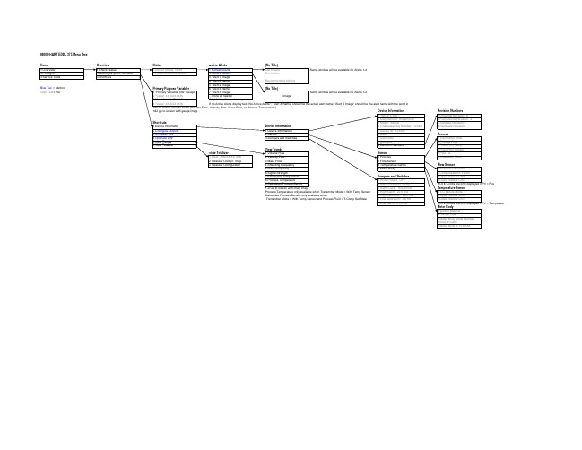
Status 1 Device Status: Good 2 Communications: Polled
Revision Numbers 1 Universal Revision: 5 2 Field Device Revision: 2 3 Software Revision: 3 4 Hardware Revision: 1 Process 1 Transmitter Mode 2 Process Fluid 3 Fixed Proc Temp 4 Fixed Proc Density 5 Pipe I.D. 6 Installation Effect Flow Sensor 1 Reference K Factor 2 Compensated K Factor 3 Upper Sensor Limit 4 Lower Sensor Limi NOTE: Limits are only displayed if PV = Flow Temperature Sensor 1 T/C Failure Mode 2 Upper Sensor Limit 3 Lower Sensor Limi NOTE: Limits are only displayed if PV = Temperatur Meter Body 1 Wetted Material 2 Flange Type 3 Meter Body Serial Number 4 Body # Suffix 5 Meter Body #: 123456A
Process Conditions 1 Fixed Proc Temp 2 Change Proc Temp Units 3 Proc Pressure (abs) 4 Change Proc Pressure (abs) 5 Proc Compressibility Base Conditions 1 Base Temperature 2 Change Base Temp 3 Base Pressure 4 Change Base Pressure 5 Base Compressibility Density/Density Ratio 1 Fixed Proc Density 2 Density Ratio
- 1、下载文档前请自行甄别文档内容的完整性,平台不提供额外的编辑、内容补充、找答案等附加服务。
- 2、"仅部分预览"的文档,不可在线预览部分如存在完整性等问题,可反馈申请退款(可完整预览的文档不适用该条件!)。
- 3、如文档侵犯您的权益,请联系客服反馈,我们会尽快为您处理(人工客服工作时间:9:00-18:30)。
Page 4
GCF Certification
The WCDMA 3G Certification Program was officially launched by GCF on 8th February 2005
Every new WCDMA phone should be certified by GCF before selling in the market
GS-8800 GS-8800 Lite GS-8800 Super Lite
GSGS-8800 RF Design Verification System
Page 7
Agilent Restricted
GSGS-8800 RF Design Verification Systems Family Configurations
Entry level users, second system users from manufacturing, R&D or QA Users who want cost-efficient design verification system
RF
RF Comm Test Set (E5515C OBT)
Technology Stage
• Baseband Development • Baseband Support Systems Development • RFICs Development
Platform Stage
• Baseband HW & FW Integration • Baseband & RF/IQ IC Integration • API & SDK (e.g. Brew) Development
GSGS-8800 Series Product Overview
Wireless Handset Design Stages
Technology/Platform Design
Architecture Technology Development Platform Development
Product Realization
Product Stage
• RF Circuit Design • Printed Circuit Board Design • RF & Baseband Integration • Mechanical Design
Reference Design
GS-8800 focus on Integration & Verification Cycle
GCF authorizes a test platform which can be used for validating 3GPP RF/Protocol conformity of UE (Handset) which is interoperable with actual WCDMA/GSM/GPRS networks
Now! 8960 Wireless Test Set + DC Power Supply + Signal Gen. + Microwave Gen. + RF Switching & Routing + Power Meter
Software Wireless Test Manager – Mandatory config Wselection AMPS, GSM/GPRS, EGPRS, cmdaOne/cdma2000, W-CDMA, 1xEVfor radio 1xEV-DO, HSDPA technologie s Agilent Restricted
6
GSbenchpreGS-8800 provides a scalable continuum of solutions from a bench-top R&D tool, to a prePage Agilent Restricted conformance system, all the way to a full conformance system based on the same hardware and software platform.
AMPS, GSM/GPRS/EGPRS, cdmaOne/cdma2000, W-CDMA, 1xEV-DO, HSDPA
Flexible and scalable platform for wireless handset design verification GSGS-8800 RF Design Verification Systems Family:
Early design verificati
Page 3
How WSSD Test Systems Help To Overcome Design Challenges
Research Platform Definition Parallel Product Product Component Integration Verification Development & Evaluation Pilot Manufacturing
Test platform for design verification prior to GCF certification is not necessarily a Full Conformance system but can also be a Partial Conformance system (test cases)
DUT
Available now!
GPIB
PC Controller
Power Supply (66319D)
GPIB
Serial
Agilent Restricted
Page 9
GSGS-8800 Lite RF Design Verification System
preReduce cost of conformance testing by pre-conformance testing Faster test speed with accurate test result Support multiple radio formats and bands GSAgilent GS-8800 provide best balance of test cost & test coverage
Agilent Restricted Page 5
Continuum of Wireless R&D System Offerings
Handset Layer (UUT) System Offerings
Layer1 (PHY)
RF Hardware
Layer2 (RLC/MAC)
Layer3 (RRC)
GSIntroduction To GS-8800 RF Design Verification Systems Family
RF design verification system for wireless handset Accelerate integration & verification cycles for wireless handset design Support multiple radio technologies:
GS-8800 Super GSLite GS-8800 Lite GSGS-8800 GS-
Launch Hardware config
Now! 8960 Wireless Test Set + DC Power Supply
Now! 8960 Wireless Test Set + DC Power Supply + Spectrum Analyzer+Divid er
Page 8
GSGS-8800 Super Lite RF Design Verification System
CostCost-efficient solution for wireless handset design verification GSLowest test coverage among the GS-8800 RF Design Verification System Family Target customer:
GS-8800 focus on Integration & Verification Cycle
Reference Platform Vertical Integration
TTM “pressure ramp”
Agilent Restricted
Robust Reference Platform
Application
Application Software / UI
Protocot & Anite partnership solutions (SAT & SAS)
GSGS-8900 Software DVS