SML-LXL1210GYC-TR中文资料
红色贴片式发光二极管XL-2012SURC产品说明书

产品承认书产品名称:0805-T0.8红色贴片式发光二极管产品型号:XL-2012SURC客户名称:客户料号:承认日期:深圳市成兴光电子科技有限公司制定审核核准客户承认栏确认审核核准一、产品描述:●外观尺寸(L/W/H): 2.0x1.25x0.8mm●颜色:高亮度红色●胶体:透明胶体●EIA规范标准包装●环保产品,符合ROHS要求●适用于自动贴片机●适用于回流焊制程二、外形尺寸及建议焊盘尺寸:C athode A nodeG reen m ark建议焊盘尺寸备注:1.单位:毫米(mm)2.公差:如无特别标注则为±0.10mm三、建议焊接温度曲线:有铅制程无铅制程四、最大绝对额定值(Ta=25℃):参数符号最大额定值单位消耗功率Pd55mW最大脉冲电流(1/10占空比,0.1ms脉宽)I FP100mA正向直流工作电流I F25mA 反向电压V R5V 工作环境温度Topr-30°C~+85°C存储环境温度Tstg-40°C~+90°C焊接条件Tsol 回流焊:260°C,10s 手动焊:300°C,3s五、光电参数(Ta=25℃):参数符号最小值代表值最大值单位测试条件光强IV 38---75mcd IF=5mA 半光强视角2θ1/2---120---deg IF=5mA 主波长λD 617---623nm IF=5mA 正向电压VF 1.85--- 2.1V IF=5mA 反向电流IR------1uAVR=5V亮度分档:代码最小值最大值单位测试条件M33845mcdIF=5mAM44560M56075电压分档:代码最小值最大值单位测试条件V1 1.85 1.9V IF=5mAV2 1.9 1.95V3 1.95 2.0V4 2.0 2.05V52.052.1波长分档:代码最小值最大值单位测试条件R1617619nmIF=5mAR2619621R3621623六、光电参数代表值特征曲线:φ60七、标签标识:CAT :光强(mcd )HUE :波长(nm )REF :电压(V )误差范围a.Luminous Intensity:±15%b.HUE:±1nmc.Forward Voltage:±0.1V八、包装载带与圆盘尺寸:φ13.0AU ser Feed D irectionAA-A剖面图备注:1.单位:毫米(mm)2.公差:如无特别标注则为±0.15mm九、圆盘及载带卷出方向及空穴规格:尾端至少160mm盖带和空壳载带的组合开始端装有零件部分至少160mm盖带和至少160mm独立盖带或空壳载带的组合盖带与空壳载带的组合十、内包装及外包装:内标签圆盘干燥剂防潮防静电袋5cartons/box外标签抽真空、热封10bags/carton十一、信赖性实验:测试项目测试条件测试次数参考标准失效判定标准失效LED数量(PCS)防潮等级1.回流焊最高温度=260℃,10秒,2次回流焊;2.回流焊之前存储条件:30℃,相对湿度=70%,168H;-JEITAED-4701300301﹟10/22焊接信赖性(无铅回流焊)回流焊最高温度=245±5℃,5秒(无铅回流焊)-JEITAED-4701303303A﹟20/22冷热循环-40℃30分钟~25℃5分钟~100℃30分钟~25℃5分钟300个循环JESD22-A104﹟10/22冷热冲击-35℃15分钟转换时间3分钟85℃15分钟300个循环JESD22-A106﹟10/22高温存储Ta=100℃1000小时JESD22-A103﹟10/22低温存储Ta=-40℃1000小时JESD22-A119﹟10/22常温老化Ta=25℃IF=20mA1000小时JESD22-A108﹟10/22(2)失效标准标准﹟项目测试条件失效标准﹟1正向电压(V F)I F=20mA>U.S.L*1.1光强(IV)I F=20mA<L.S.L*0.7反向电流(I R)V R=5V>U.S.L*2.0﹟2焊接可靠性/锡膏覆盖焊盘比例小于95%★U.S.L:规格上限L.S.L:规格下限十二、使用注意事项:◆使用:1.过高的温度会影响LED的亮度以及其他性能,所以为使LED有较好的性能表现,应将LED远离热源。
UN1210中文资料
3.5±0.1
1.0 2.4±0.2 2.0±0.2
0.45±0.05 2 1 2.5
1.0±0.1
R 0. 7
0.85
0.55±0.1
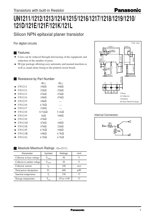
s Resistance by Part Number
q q q q q q q q q q q q q q q
UN1211 UN1212 UN1213 UN1214 UN1215 UN1216 UN1217 UN1218 UN1219 UN1210 UN121D UN121E UN121F UN121K UN121L
120 100 80 60
0.7mA 0.6mA 0.5mA 0.4mA 0.3mA
Forward current transfer ratio hFE
Collector current IC (mA)
300 Ta=75˚C
200 25˚C 100 –25˚C
0.2mA 40 20 0 0 2 4 6 8 10 12
3
2.5
1:Base 2:Collector 3:Emitter M Type Mold Package
Internal Connection
R1
1.25±0.05
C
B
R2
E
s Absolute Maximum Ratings
Parameter Collector to base voltage Collector to emitter voltage Collector current Total power dissipation Junction temperature Storage temperature Symbol VCBO VCEO IC PT Tj Tstg
TMCM-1210 硬件手册说明书

TRINAMIC Motion Control GmbH & Co. KGHamburg, GermanyHardware Version V 1.10HARDWARE MANUAL+ +TMCM-12101-Axis steppercontroller/drivermax. 0.6A RMS / 24V DC STOP / HOME switch input hall sensorRS485++Table of contents1Life support policy (3)2Features (4)3Order codes (5)4Mechanical and Electrical Interfacing (6)4.1Dimensions and Mounting Holes (6)4.2Board mounting considerations (6)4.3Connectors (7)4.3.1Power, RS485 + HOME connector (8)4.3.2Motor connector (9)4.4Power supply (9)4.5RS485 (10)5Motor driver current (12)6On-Board LEDs (13)7Reset to Factory Default Values (13)8EMC considerations (14)9Operational Ratings (15)10Functional Description (16)11Revision History (17)11.1Document revision (17)11.2Hardware revision (17)12References (17)1Life support policyTRINAMIC Motion Control GmbH & Co. KG does not authorize or warrant any of its products for use in life support systems, without the specific written consent of TRINAMIC Motion Control GmbH & Co. KG.Life support systems are equipment intended to support or sustain life, and whose failure to perform, when properly used in accordance with instructions provided, can be reasonably expected to result in personal injury or death.© TRINAMIC Motion Control GmbH & Co. KG 2015 - 2019Information given in this data sheet is believed to be accurate and reliable. However neither responsibility is assumed for the consequences of its use nor for any infringement of patents or other rights of third parties, which may result from its use.Specifications are subject to change without notice.2FeaturesThe TMCM-1210 is a highly compact 20mm x 20mm single axis stepper motor controller and driver board with RS485 interface. It has been designed in order to be mounted on the rear side of a NEMA8 (20mm flange size) stepper motor and offers an integrated hall-sensor based encoder IC in addition to a reference switch input for easy homing / search of reference position. The module supports motor currents up to 0.6A RMS and supply voltages up to 24V DC nominal. It is available with standard TMCL firmware and supports stand-alone operation (TMCL programs with auto-start stored on-board) and remote control via RS485 interface.MAIN CHARACTERISTICSMotion controller∙Motion profile calculation in hardware in real-time∙Motion controller supports linear and sixPoint™ ramps∙On the fly alteration of motor parameters (e.g. position, velocity, acceleration)∙High performance microcontroller (Cortex-M0+) for overall system control and serial communication protocol handlingBipolar stepper motor driver∙Up to 256 microsteps per full step∙Highly integrated and highly-efficient operation∙Dynamic current control∙stallGuard2™ feature for stall detectionInterfaces∙RS485 2-wire communication interface∙Digital input IN0 (+24V compatible), can be used as reference switch or left and/or right stop switch input, alsoOn board hall sensor∙Absolute sensor within one motor rotation∙12bit / 4096 steps / revolution max.∙Low-cost sensor - suitable for low velocity applications (few hundred rpm) –e.g. initial reference search (together with HOME sensor input) after power-upSoftware∙TMCL™ remote (direct mode) and standalone oper ation with memory for up to 876 TMCL commands∙Fully supported by TMCL-IDE (PC based integrated development environment)Electrical data∙Supply voltage: +7V… +30V DC∙Motor current: up to 0.6A RMS (programmable)Mechanical data∙Board size: 20mm x 20mm, overall height 9mm max. (without mating connectors and cables)∙Mounting holes compatible with NEMA 8 stepper motors (for mounting the board to the rear side of a NEMA8 stepper motor using two of the four existing screw)Please see separate TMCM-1210 Firmware Manual for additional information regarding firmware functionality and TMCL programming.3Order codesThe TMCM-1210 is available as:A cable loom set is available for this module, also:Table 3.2: Cable loom order code4 Mechanical and Electrical Interfacing4.1 Dimensions and Mounting HolesThe dimensions of the board are approx. 20mm x 20mm x 9 mm in order to fit on the back side of a 20mm (NEMA8) stepper motor. Maximum component height (height above PCB level) without mating connectors is around 6mm above PCB level and 2 mm below PCB level. There are two mounting holes for M2 screws for mounting to a NEMA8 stepper motor.2xFigure 4.1 Dimensions of TMCM-1210 and position of mounting holes (with comparison of size)4.2 Board mounting considerationsThe TMCM-1210 offers two metal plated mounting holes. Both mounting holes are connected to power supply ground. Please keep this in mind when mounting the board to the rear side of a motor.Figure 4.2: Example of TMCM-1210 mounted to NEMA 8 stepper motor4.3 ConnectorsThe TMCM-1210 offers two connectors including the motor connector which is used for attaching the motor coils to the electronics. The Power, RS485 and HOME connector is used for power supply, RS485 serial wire communication and offers one digital input.4115Power, RS485 + HOME connector HOME 5RS485+RS485-34VDD GND 12IN0STOP_L / STOP_R Motor connectorOA1OA234OB1OB212Figure 4.2 Overview connectorsOverview of connectors and mating connectors types:Table 4.1: Connectors and mating connectors, contacts and applicable wire4.3.1Power, RS485 + HOME connectorThe module offers one combined power, RS485 2-wire serial communication and digital input (HOME) connector (JST PH series).51Table 4.2: Power, RS485 + IN0 connector4.3.2 Motor connectorAs motor connector a 4pin JST PH-series 2mm pitch single row connector is available. The motor connector is used for connecting the four motor wires of the two motor coils of the bipolar stepper motor to the electronics. 14Table 4.4: Motor connector 4.4 Power supplyFor proper operation care has to be taken with regard to power supply concept and design. Due to space restrictions the TMCM-1210 includes just about 20µF/35V of supply filter capacitors. These are ceramic capacitors which have been selected for high reliability and long life time.4.5RS485For remote control and communication with a host system the TMCM-1210 provides a two wire RS485 bus interface. For proper operation the following items should be taken into account when setting up an RS485 network:1.BUS STRUCTURE:The network topology should follow a bus structure as closely as possible. That is, the connection between each node and the bus itself should be as short as possible. Basically, it should be short compared to the length of the bus.termination resistor (120 Ohm)termination resistor (120 Ohm)Figure 4.6: Bus structure2.BUS TERMINATION:Especially for longer busses and/or multiple nodes connected to the bus and/or high communication speeds, the bus should be properly terminated at both ends. The TMCM-1210 does not integrate any termination resistor. Therefore, 120 Ohm termination resistors at both ends of the bus have to be added externally.3.NUMBER OF NODES:The RS485 electrical interface standard (EIA-485) allows up to 32 nodes to be connected to a single bus.The bus transceiver used on the TMCM-1210 unit (SN65HVD3085E) has a significantly reduced bus load and allow a maximum of 255 units to be connected to a single RS485 bus using TMCL firmware. Please note: usually it cannot be expected to get reliable communication with the maximum number of nodes connected to one bus and maximum supported communication speed at the same time. Instead, a compromise has to be found between bus cable length, communication speed and number of nodes. MUNICATION SPEED:The maximum RS485 communication speed supported by the TMCM-1210 hardware is 1Mbit/s. Factory default is 9600 bit/s. Please see separate TMCM-1210 TMCL firmware manual for information regarding other possible communication speeds below the upper limit in hardware.5.NO FLOATING BUS LINES:Avoid floating bus lines while neither the host/master nor one of the slaves along the bus line is transmitting data (all bus nodes switched to receive mode). Floating bus lines may lead to communication errors. In order to ensure valid signals on the bus it is recommended to use a resistor network connecting both bus lines to well defined logic levels.There are actually two options which can be recommended:Add resistor (Bias) network on one side of the bus, only (120R termination resistor still at both ends):termination resistor(120R)RS485- / RS485Btermination resistor (120R)RS485+ / RS485AFigure 4.7: Bus lines with resistor (Bias) network on one side, onlyOr add resistor (Bias) network at both ends of the bus (like Profibus™ termination):termination resistor (220R)RS485- / RS485BRS485+ / RS485A termination resistor (220R)Figure 4.8: Bus lines with resistor (Bias) network at both endsCertain RS485 interface converters available for PCs already include these additional resistors (e.g. USB-2-485 with bias network at one end of the bus).5Motor driver currentThe on-board stepper motor driver operates current controlled. The driver current may be programmed in software with 32 effective scaling steps in hardware.Explanation of different columns in table below:Motor current setting in software (TMCL)These are the values for TMCL axis parameter 6 (motor run current) and 7 (motor standby current). They are used to set the run / standby current using the following TMCL commands:SAP 6, 0, <value> // set run currentSAP 7, 0, <value> // set standby current(read-out value with GAP instead of SAP. Please see separate TMCM-1210 firmware manual for further information)Motor currentI RMS [A]Resulting motor current based on motor current setting6On-Board LEDsThe board offers one LED in order to indicate board status. The function of the LED is dependent on the firmware version. With standard TMCL firmware the green LED should be flashing slowly during operation.GREEN LEDFigure 6.1 On-board LED7Reset to Factory Default ValuesIn order to reset all settings (e.g. incl. address and RS485 baud rate) to factory default values please follow instruction sequence below:1.Switch OFF power supply.2.Short programming pads on bottom of PCB as shown in figure 7.1.3.Switch ON power supply (on-board LED should start flashing fast).4.Switch OFF power supply.5.Remove short circuit.Figure 7.1 Reset to factory default values (bottom view of pcb)8EMC considerationsThe TMCM-1210 contains ferrite beads on-board in line with the positive supply input and all 4 motor windings connections in addition to filter capacitors.Tests have shown that it is possible to meet Class B emission standards using the bare TMCM-1210 (motor and power connected) with the motor running slowly at maximum current (0.7A RMS) and +24V supply voltage without additional / external filters.Figure8.1:SetupwithTMCM-1210andattachedmotor(***************************/24Vsupply,stand-alone mode using on-board TMCL-autostart-program)Figure 8.2: measurement results (example)Please note that these measurement results using a bare TMCM-1210 unit with only motor and power supply connected do not imply any guarantee for a complete system with one or more integrated TMCM-1210 with meeting any emission limits.9Operational RatingsThe operational ratings show the intended or the characteristic ranges and should be used as design values. In no case shall the maximum values be exceeded!Table 9.1 General operational ratings of modulePERATIONAL RATINGS OF SWITCHTable 9.2 Operational ratings of HOME + STOP switches / IN0 inputsPERATIONAL RATINGS OF INTERFACETable 9.3: Operational ratings of RS485 interface10Functional DescriptionThe TMCM-1210 is a highly integrated controller/driver module which can be controlled via several serial interfaces. Communication traffic is kept low since all time critical operations (e.g. ramp calculations) are performed on board. The nominal supply voltage of the unit is 12V or 24V DC. The module is designed for both, standalone operation and direct mode. Full remote control of device with feedback is possible. The firmware of the module can be updated via the RS485 serial interfaces.In Figure 10.1 the main parts of the TMCM-1210 are shown:∙microprocessor, which runs the TMCL operating system (connected to TMCL memory),∙motion controller (part of TMC2130), which calculates ramps and speed profiles internally by hardware, ∙driver (part of TMC2130) with stallGuard2™ and its energy efficient coolStep™ feature and stealthCh o p™ for extremely quiet operation∙hall sensor based encoder which delivers position feedback at low speed (few 100rpm max.) – can be used for reference search e.g. after power-up7…Figure 10.1 Main parts of the TMCM-121011Revision History11.1D ocument revisionTable 11.1: Document revision11.2H ardware revisionTable 11.2: Hardware revision12References[JST] JST connector[TMC2130] TMC2130 datasheetManual available on [TMCL-IDE] TMCL-IDE User ManualManual available on .。
SL2.2S规格书,usb HUB大全,替换FE1.1S,GL850,GL852,PL2586
USB2.0 HUB控制器集成电路USB 2.0 HIGH SPEED 4-PORT HUB CONTROLLERSL2.2s数据手册Data Sheet内容目录第一章管脚分配 (3)1.1 SL2.2S管脚图 (3)1.2 SL2.2S管脚定义 (3)第二章 功能叙述 (5)2.1综述 (5)2.2指示灯 (5)2.2.1单灯方案 (5)2.2.2多灯方案 (6)2.2.3 LED指示定义 (6)2.3过流保护 (6)2.4充电支持 (6)2.5I2C接口 (7)2.6EEPROM设置 (7)第三章电气特性 (8)3.1极限工作条件 (8)3.2工作范围 (8)3.3直流电特性 (8)3.4HS/FS/LS电气特性 (8)3.5ESD特性 (8)附录一封装 (9)表格目录表格1: 端口LED定义 (6)表格 2 : ACTIVE LED定义 (6)表格3:EEPROM数据结构定义 (7)表格4: 最大额定值 (8)表格5: 工作范围 (8)表格6: 直流电特性 (8)插图目录图1:SSOP28 管脚图 (3)图2:单灯方案配置 (5)图3: 5灯方案配置 ............................................................................... (6)图 4:附录 封装图 ................................................................................... .9第一章管脚分配1.1SL2.2s管脚图图1:SSOP28 管脚图1.2SL2.2s管脚定义管脚名称28Die IO类型定义Pin#VSS 1 P 芯片地XOUT 2 O晶振PAD XIN 3 IDM4 4 B下行口4的USB信号DP4 5 BDM3 6 B下行口3的USB信号DP3 7 BDM2 8 B下行口2的USB信号DP2 9 BDM1 10 B下行口1的USB信号DP1 11 BVDD18 12 P 模拟1.8vVDD33 13 P 模拟3.3v - 14 NCUDM 15 B上行口的USB信号UDP 16 BRESET_N 17 I,Pu 芯片外部复位输入- 18 NCPSELF 19 I,Pu 高为自供电,低为总线供电VDD5 20 P 5v输入VDD33 21 P 3.3v输出DRV 22 B,Pu 点灯驱动信号LED1 23 B,Pu 点灯驱动信号LED2 24 B,Pu 点灯驱动信号PWRN 25 B,Pu 下行口电源输出控制,低有效OVCRN/SDA 26 B,PuI2C SDA数据线,内部上拉;芯片初始化完成后作为过流保护输入脚,低有效SCL 27 B,Pu I2C SCL时钟输出VDD18 28 P 数字1.8v注释:O,输出;I 输入;B 双向;P 电源/接地;Pu 上拉;Pd 下拉;NC 悬空;第二章 功能叙述2.1综述SL2.2s 是一颗高集成度,高性能,低功耗的USB2.0集线器主控芯片;该芯片采用STT 技术,单电源供电方式,芯片供电电压为5v , 内部集成5V 转3.3V,只需在外部电源添加滤波电容;芯片自带复位电路,低功耗技术让他更加出众。
贴片压敏电阻1210封装参数型号规格书大全
The specimen should be subjected to -40℃, without load for 1000 hours and then Low Temperature Storage stored at room temperature for one two hours. The change of varistor voltage shall be
Pulse Rated peak single pulse transient current : Measured by
8/20µs Pulse
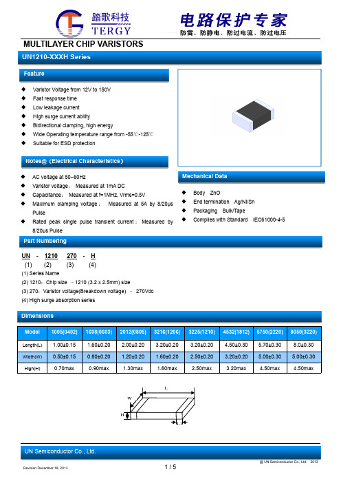
Part Numbering
Mechanical Data
Body ZnO End termination Ag/Ni/Sn Packaging Bulk/Tape Complies with Standard IEC61000-4-5
B0
K0
±0.10 ±0.10
1.88 1.04
T ±0.05 0.22
T2
D0
±0.05 +0.10
0.87 1.50
D1 ±0.05
1.00
P1
P2
±0.10 ±0.05
4.00 2.00
P0 ±0.05
4.00
W ±0.20 8.00
VB
12
10-14
18
15.5-21
21
19-23
24
22-27
27
24-30
30
27-33
33
29-36
37
32-39
39
35-43
47
42-52
53
47-58.5
56
TMX320C6211BGLW100资料

Table of Contents GHK BGA package (bottom view) . . . . . . . . . . . . . . . . . . . 3 description . . . . . . . . . . . . . . . . . . . . . . . . . . . . . . . . . . . . . . . 4 device characteristics . . . . . . . . . . . . . . . . . . . . . . . . . . . . . . 5 functional and CPU (DSP core) block diagram . . . . . . . . . 6 CPU (DSP core) description . . . . . . . . . . . . . . . . . . . . . . . . 7 memory map summary . . . . . . . . . . . . . . . . . . . . . . . . . . . . . 9 signal groups description . . . . . . . . . . . . . . . . . . . . . . . . . . 10 signal descriptions . . . . . . . . . . . . . . . . . . . . . . . . . . . . . . . . development support . . . . . . . . . . . . . . . . . . . . . . . . . . . . . . documentation support . . . . . . . . . . . . . . . . . . . . . . . . . . . . clock PLL . . . . . . . . . . . . . . . . . . . . . . . . . . . . . . . . . . . . . . . power-down mode logic . . . . . . . . . . . . . . . . . . . . . . . . . . . power-supply sequencing . . . . . . . . . . . . . . . . . . . . . . . . . . absolute maximum ratings over operating case temperature range . . . . . . . . . . . . . . . . . . . . . . . . . . . recommended operating conditions . . . . . . . . . . . . . . . . . recommended operating conditions (PCI only) . . . . . . . . electrical characteristics over recommended rangesof supply voltage and operating case temperature . . . . . . . . . . . . . . . . . . . . . . . . . . . . electrical characteristics over recommended ranges of supply voltage and operating case temperature (PCI only) . . . . . . . . . . . . . . . . . . . . . . . 13 22 25 26 28 31 32 32 32 33 33 parameter measurement information . . . . . . . . . . . . . . . 34 input and output clocks . . . . . . . . . . . . . . . . . . . . . . . . . . . 35 asynchronous memory timing . . . . . . . . . . . . . . . . . . . . . 37 synchronous-burst memory timing . . . . . . . . . . . . . . . . . 40 synchronous DRAM timing . . . . . . . . . . . . . . . . . . . . . . . . 42 HOLD/HOLDA timing . . . . . . . . . . . . . . . . . . . . . . . . . . . . 46 reset timing . . . . . . . . . . . . . . . . . . . . . . . . . . . . . . . . . . . . . 47 external interrupt timing . . . . . . . . . . . . . . . . . . . . . . . . . . 49 PCI I/O timings . . . . . . . . . . . . . . . . . . . . . . . . . . . . . . . . . . 50 PCI reset timing . . . . . . . . . . . . . . . . . . . . . . . . . . . . . . . . . 51 PCI serial EEPROM interface timing . . . . . . . . . . . . . . . 52 multichannel buffered serial port timing . . . . . . . . . . . . . 53 DMAC, timer, power-down timing . . . . . . . . . . . . . . . . . . 63 JTAG test-port timing . . . . . . . . . . . . . . . . . . . . . . . . . . . . 65 mechanical data . . . . . . . . . . . . . . . . . . . . . . . . . . . . . . . . . 66 revision history . . . . . . . . . . . . . . . . . . . . . . . . . . . . . . . . . . 67
施耐德 LC1N1210M5N 接触器 Easy TeSys Control 数据表

Product data sheetCharacteristicsLC1N1210M5NEasy TeSys Control 3P 接触器 (1NO) - AC-3 -<= 440V 12A - 220V 线圈 50Hz主要信息产品系列Easy TeSys 产品系列Easy TeSys Control 产品类型接触器产品短名LC1N接触器应用领域应用于功率因数大于等于0.95的交流负载中应用于无感或微感负载、电阻炉使用类别AC-3 AC-1AC-4极数3P额定工作电压 [Ue]电源回路: <= 690 V AC 50/60 Hz额定工作电流 [Ie]12 A (当运行温度 <=60 °C) 当运行电压<=<= 440 V AC AC-3对于电源回路 25 A (当运行温度 <=60 °C) 当运行电压<=<= 440 V AC AC-1对于电源回路 5 A (当运行温度 <=60 °C) 当运行电压<=<= 440 V AC AC-4对于电源回路控制回路电压 [Uc]220 V AC 50 Hz补充信息电动机功率 (kW)3 KW 当运行电压<=220...230 V AC 50/60 Hz 5.5 KW 当运行电压<=380...400 V AC 50/60 Hz 5.5 KW 当运行电压<=415...440 V AC 50/60 Hz 7.5 KW 当运行电压<=500 V AC 50/60 Hz7.5 KW 当运行电压<=660...690 V AC 50/60 Hz 回路触点类型 3 NO约定发热电流 [Ith]25 A (当运行温度 <=60 °C) 对于电源回路额定接通能力 [Irms]120 A 当运行电压<=380 V AC 对于电源回路 符合 IEC 60947-4-1 140 A AC 对于辅助触点 符合 IEC 60947-5-1额定分断能力96 A 当运行电压<=440 V 对于电源回路 符合 IEC 60947额定短时耐受电流 [Icw]105 A 当运行温度<=40 °C 可持续10 s 对于电源回路 61 A 当运行温度<=40 °C 可持续60 s 对于电源回路 30 A 当运行温度<=40 °C 可持续600 s 对于电源回路与继电器配合使用的熔丝10 A gG 当运行电压<=<= 690 V 配合 1 型, 对于控制回路 符合 IEC 60947-5-1 25 A gG 当运行电压<=<= 690 V 配合 1 型, 对于电源回路平均阻抗 2.5 MΩ - Ith 25 A 50 Hz 对于电源回路每极功耗0.36 W AC-3 1.6 W AC-1额定绝缘电压 [Ui]690 V 符合 IEC 60947-4-1过电压类别III 污染等级3额定冲击耐受电压 [Uimp]6 KV 线圈未连接到电源电路 符合 IEC 60947T h e i n f o r m a t i o n p r o v i d e d i n t h i s d o c u m e n t a t i o n c o n t a i n s g e n e r a l d e s c r i p t i o n s a n d /o r t e c h n i c a l c h a r a c t e r i s t i c s o f t h e p e r f o r m a n c e o f t h e p r o d u c t s c o n t a i n e d h e r e i n .T h i s d o c u m e n t a t i o n i s n o t i n t e n d e d a s a s u b s t i t u t e f o r a n d i s n o t t o b e u s e d f o r d e t e r m i n i n g s u i t a b i l i t y o r r e l i a b i l i t y o f t h e s e p r o d u c t s f o r s p e c i f i c u s e r a p p l i c a t i o n s .I t i s t h e d u t y o f a n y s u c h u s e r o r i n t e g r a t o r t o p e r f o r m t h e a p p r o p r i a t e a n d c o m p l e t e r i s k a n a l y s i s , e v a l u a t i o n a n d t e s t i n g o f t h e p r o d u c t s w i t h r e s p e c t t o t h e r e l e v a n t s p e c i f i c a p p l i c a t i o n o r u s e t h e r e o f .N e i t h e r S c h n e i d e r E l e c t r i c I n d u s t r i e s S A S n o r a n y o f i t s a f f i l i a t e s o r s u b s i d i a r i e s s h a l l b e r e s p o n s i b l e o r l i a b l e f o r m i s u s e o f t h e i n f o r m a t i o n c o n t a i n e d h e r e i n .机械寿命10000000 次电气寿命1400000 次 AC-3300000 次 AC-1250000 次 AC-4控制回路特性AC当50 Hz控制电压限额0.85...1.1 Uc (-5…55 °C 线圈吸合 50 Hz0.3...0.6 Uc (-5…55 °C 线圈释放 50 Hz(~50Hz吸合)功耗 (VA)95 VA 50 Hz cos phi 0.75 (at 20 °C)(~50Hz保持)功耗 (VA)8.5 VA 50 Hz cos phi 0.3 (at 20 °C)热消散2…3 W for 控制回路动作时间12...22 ms 闭合过程4...19 ms 打开过程最大操作频率1800 次/小时当60 °C接线能力电源回路: 螺栓紧固 1 1…4 mm² 电缆类型: 软线 带接线端子电源回路: 螺栓紧固 2 1…2.5 mm² 电缆类型: 软线 带接线端子电源回路: 螺栓紧固 1 1…4 mm² 电缆类型: 硬线 不带接线端子电源回路: 螺栓紧固 2 1…4 mm² 电缆类型: 硬线 不带接线端子控制回路: 螺栓紧固 1 1…4 mm² 电缆类型: 软线 不带接线端子控制回路: 螺栓紧固 2 1…4 mm² 电缆类型: 软线 不带接线端子控制回路: 螺栓紧固 1 1…4 mm² 电缆类型: 软线 带接线端子控制回路: 螺栓紧固 2 1…2.5 mm² 电缆类型: 软线 带接线端子控制回路: 螺栓紧固 1 1…4 mm² 电缆类型: 硬线 不带接线端子控制回路: 螺栓紧固 2 1…4 mm² 电缆类型: 硬线 不带接线端子紧固扭矩电源回路: 1.2 N.m控制回路: 1.2 N.m辅助触点类型 1 NO最小开关电压17 V 对于控制回路最小开关电流 [Imin]5 MA 对于控制回路绝缘电阻> 10 MΩ 对于控制回路不重迭时间 1.5 Ms 得电 确保NC和NO触电之间1.5 Ms 失电 确保NC和NO触电之间安装方式底板安装DIN 导轨安装环境标准EN 60947-4-1IEC 60947-4-1IEC 60947-1GB 14048.4EN 60947-1产品认证CCCIP 保护等级IP20 符合 IEC 60529防护措施TH (污染等级 3) 符合 IEC 60068周围空气温度-5…55 °C 运行-60…80 °C 存储-20…70 °C (运行在Uc下时)工作海拔3000 m 无降容耐火及耐异常高温能力850 °C 符合 IEC 60695-2-1抗冲击、震动性能抗震性能 触点打开时 (1.5 gn (5...300 Hz))抗震性能 触点闭合时 (3 gn (5...300 Hz))抗冲击性能 触点打开时 (7 gn (11ms))抗冲击性能 触点闭合时 (10 gn (11ms))高度74 Mm宽度45 Mm深度80 Mm净重0.3 Kg包装单位Unit Type of Package 1PCENumber of Units in Package 11Package 1 Height 4.82 CmPackage 1 Width7.4 CmPackage 1 Length8.31 CmPackage 1 Weight341.0 GUnit Type of Package 2S02Number of Units in Package 236Package 2 Height15.0 CmPackage 2 Width30.0 CmPackage 2 Length40.0 CmPackage 2 Weight12.5 KgUnit Type of Package 3PALNumber of Units in Package 3576Package 3 Height60.0 CmPackage 3 Width80.0 CmPackage 3 Length60.0 CmPackage 3 Weight196.466 Kg可持续性产品类型Green Premium 产品REACh法规REACh 声明REACh(不含 SVHC)是欧盟ROHS指令符合欧盟ROHS声明无有毒重金属是无汞是中国 ROHS 管理办法中国 ROHS 声明RoHS 豁免信息是环境披露产品环境文件流通资料产品使用寿命终期信息WEEE该产品必须经特定废物回收处理后弃置于欧盟市场,绝不可丢弃于垃圾桶中。
msc1210中文
参数
模拟输入 AIN0-AIN7 AINCOM 模拟输入范
围
全输入电压范围 差分输入阻抗
输入电流 带宽
快速沉积滤波器 Sinc2滤波器 Sinc2滤波器
可编程增益放大器 输入电容 输入漏电流 熔断电流
偏移DAC 偏移DAC范围 偏移DAC单调性 偏移DAC增益偏差 偏移DAC增益偏差漂移
条件
缓冲区关闭 缓冲区打开 IN+ - IN- 看图4 缓冲区关闭 缓冲区打开
256
内部 MOVX 静态随机存储器 字节 1024
1024
1024
1024
数
外部可存取存储器 字节数
程序 64K 数据 64K
程序 64K 数据 64K
程序 64K 数据 64K
程序 64K 数据 64K
注释 1 所有器件的外围特性相同 仅闪存容量不同 2 类型号的最后一位数字代表片内闪存容量 的大小= 2N KB
DC下 fCM = 60Hz, fDATA = 10Hz fCM = 50Hz, fDATA = 50Hz fCM = 60Hz, fDATA = 60Hz fSIG = 50Hz, fDATA = 50Hz fSIG = 60Hz, fDATA = 60Hz
DC下 dB =–20log( VOUT/ VDD)
MSC1210YX
最小值
典型值
最大值
单位
AGND-0.1 AGND
1
5/PGA 0.5
AVDD+0.1
AVDD-1.5
+VREF/PGA
0.469 • fDATA 0.318 • fDATA 0.262 • fDATA
9 0.5 +6
128